lock GMC YUKON 2023 Owners Manual
[x] Cancel search | Manufacturer: GMC, Model Year: 2023, Model line: YUKON, Model: GMC YUKON 2023Pages: 432, PDF Size: 9.3 MB
Page 286 of 432
GMC Yukon/Yukon XL/Denali Owner Manual (GMNA-Localizing-U.S./
Canada/Mexico-16417394) - 2023 - CRC - 5/16/22
Driving and Operating 285
After loading the trailer, separately weigh
the trailer and then the trailer tongue and
calculate the trailer load balance percentage
to see if the weights and distribution are
appropriate for your vehicle. If the trailer
weight is too high, it may be possible to
transfer some of the cargo into your vehicle.
If the trailer tongue weight is too high or
too low, it may be possible to rearrange
some of the cargo inside of the trailer.
Do not exceed the maximum allowable
tongue weight for your vehicle. Use the
shortest hitch extension available to position
the hitch ball closer to your vehicle. This will
help reduce the effect of the trailer tongue
weight on the trailer hitch and the rear axle.
If a cargo carrier is used in the trailer hitch
receiver, choose a carrier that positions the
load as close to the vehicle as possible.
Make sure the total weight, including the
carrier, is no more than half of the
maximum allowable tongue weight for the
vehicle or 227 kg (500 lb), whichever is less.Rear Gross Axle Weight Rating
(GAWR-RR)
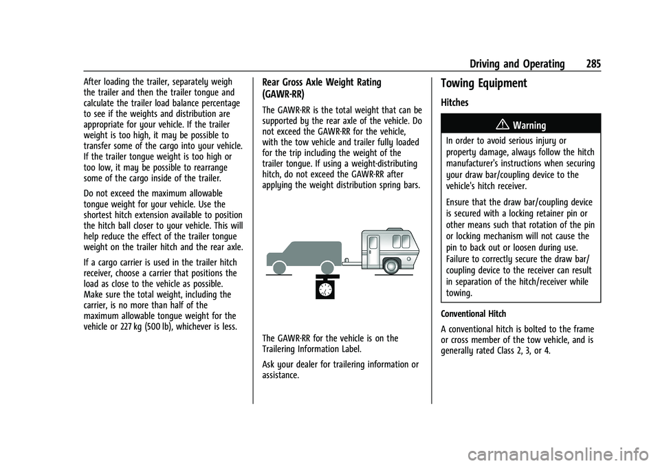
The GAWR-RR is the total weight that can be
supported by the rear axle of the vehicle. Do
not exceed the GAWR-RR for the vehicle,
with the tow vehicle and trailer fully loaded
for the trip including the weight of the
trailer tongue. If using a weight-distributing
hitch, do not exceed the GAWR-RR after
applying the weight distribution spring bars.
The GAWR-RR for the vehicle is on the
Trailering Information Label.
Ask your dealer for trailering information or
assistance.
Towing Equipment
Hitches
{Warning
In order to avoid serious injury or
property damage, always follow the hitch
manufacturer's instructions when securing
your draw bar/coupling device to the
vehicle's hitch receiver.
Ensure that the draw bar/coupling device
is secured with a locking retainer pin or
other means such that rotation of the pin
or locking mechanism will not cause the
pin to back out or loosen during use.
Failure to correctly secure the draw bar/
coupling device to the receiver can result
in separation of the hitch/receiver while
towing.
Conventional Hitch
A conventional hitch is bolted to the frame
or cross member of the tow vehicle, and is
generally rated Class 2, 3, or 4.
Page 290 of 432
GMC Yukon/Yukon XL/Denali Owner Manual (GMNA-Localizing-U.S./
Canada/Mexico-16417394) - 2023 - CRC - 5/16/22
Driving and Operating 289
MeasurementHeight Example 1500 (mm)
H1 1 000
H2 1 060
H2−H1 60
(H2−H1)/3 20
H2–[(H2−H1)/3] 1 040
Tires
.Do not tow a trailer while using a
compact spare tire on the vehicle.
.Tires must be properly inflated to support
loads while towing a trailer. SeeTires
0 340 for instructions on proper tire
inflation.
Safety Chains
Always attach chains between the vehicle
and the trailer, and attach the chains to the
holes on the trailer hitch platform.
Instructions about safety chains may be
provided by the hitch manufacturer or by
the trailer manufacturer.
If the trailer being towed weighs up to
2 271 kg (5,000 lb) with a factory-installed
step bumper, safety chains may be attached to the attaching points on the bumper;
otherwise, safety chains should be attached
to holes on the trailer hitch.
Cross the safety chains under the tongue of
the trailer to help prevent the tongue from
contacting the road if it becomes separated
from the hitch. Always leave just enough
slack so the combination can turn. Never
allow safety chains to drag on the ground.Trailer Brakes
Loaded trailers over 900 kg (2,000 lb) must
be equipped with brake systems and with
brakes for each axle. Trailer braking
equipment conforming to Canadian
Standards Association (CSA) requirement
CAN3-D313, or its equivalent, is
recommended.
When trailers cannot be detected, the
trailer-related DIC messages and/or
Trailering App alerts will not be displayed.
State or local regulations may require
trailers to have their own braking system if
the loaded weight of the trailer exceeds
certain minimums that can vary from state
to state. Read and follow the instructions for
the trailer brakes so they are installed,
adjusted, and maintained properly. Never
attempt to tap into your vehicle's hydraulic
brake system. If you do, both the vehicle
anti-lock brakes and the trailer brakes may
not function, which could result in a crash.
Page 292 of 432
GMC Yukon/Yukon XL/Denali Owner Manual (GMNA-Localizing-U.S./
Canada/Mexico-16417394) - 2023 - CRC - 5/16/22
Driving and Operating 291
towing a trailer, the arrows on the
instrument cluster illuminate even if the
trailer is not properly connected or the bulbs
are burned out.
Tow/Haul Mode
For instructions on how to enter Tow/Haul
mode, seeDriver Mode Control 0217.
Tow/Haul assists when pulling a heavy
trailer or a large or heavy load.
Tow/Haul Mode is designed to be most
effective when the vehicle and trailer
combined weight is at least 75% of the
vehicle's Gross Combined Weight Rating
(GCWR). See “Maximum Trailer Weight”
under Trailer Towing 0281.
Tow/Haul Mode is most useful when towing
a heavy trailer or carrying a large or
heavy load:
.through rolling terrain
.in stop-and-go traffic
.in busy parking lots
Operating the vehicle in Tow/Haul Mode
when lightly loaded or not towing will not
cause damage; however, it is not
recommended and may result in unpleasant
engine and transmission driving
characteristics and reduced fuel economy.
Integrated Trailer Brake Control System
The vehicle may have an Integrated Trailer
Brake Control (ITBC) system for use with
electric trailer brakes or most electric over
hydraulic trailer brake systems. These
instructions apply to both types of electric
trailer brakes.
This symbol is on the Trailer Brake Control
Panel on vehicles with an ITBC system. The
power output to the trailer brakes is
proportional to the amount of vehicle
braking. This available power output to the
trailer brakes can be adjusted to a wide
range of trailering situations.
The ITBC system is integrated with the
vehicle’s brake, anti-lock brake, and
StabiliTrak/Electronic Stability Control (ESC)
systems. In trailering conditions that cause
the vehicle’s anti-lock brake or StabiliTrak/
ESC systems to activate, power sent to the
trailer's brakes will be automatically adjusted to minimize trailer wheel lock-up.
This does not imply that the trailer has
StabiliTrak/ESC.
If the vehicle’s brake, anti-lock brake,
or StabiliTrak/ESC systems are not
functioning properly, the ITBC system may
not function fully or at all. Make sure all of
these systems are fully operational to allow
the ITBC system to function properly.
The ITBC system is powered through the
vehicle's electrical system. Turning the
ignition off will also turn off the ITBC
system. The ITBC system is fully functional
only when the ignition is in ON/RUN.
{Warning
Connecting a trailer that has an air brake
system may result in reduced or
complete loss of trailer braking, including
increased stopping distance or trailer
instability which could result in serious
injury, death, or property damage. Only
use the ITBC system with electric or
electric over hydraulic trailer brake
systems.
Page 294 of 432
GMC Yukon/Yukon XL/Denali Owner Manual (GMNA-Localizing-U.S./
Canada/Mexico-16417394) - 2023 - CRC - 5/16/22
Driving and Operating 293
lamps will come on when either vehicle
brakes or manual trailer brakes are applied
and properly connected.
Trailer Gain Adjustment Procedure
Trailer Gain should be set for a specific
trailering condition and it must be
readjusted anytime vehicle loading, trailer
loading, or road surface conditions change.
{Warning
Trailer brakes that are over-gained or
under-gained may not stop the vehicle
and the trailer as intended and can result
in a crash. Always follow the instructions
to set the Trailer Gain for the proper
trailer stopping performance.
To adjust Trailer Gain for each towing
condition: 1. Drive the vehicle with the trailer attached on a level road surface
representative of the towing condition
and free of traffic at about 32 to
40 km/h (20 to 25 mph) and fully apply
the Manual Trailer Brake apply lever. Note
Adjusting Trailer Gain at speeds lower than
32 to 40 km/h (20 to 25 mph) may result in
an incorrect gain setting.
2. Adjust the Trailer Gain, using the Trailer Gain adjustment buttons, to just below
the point of trailer wheel lock-up,
indicated by trailer wheel squeal or tire
smoke when a trailer wheel locks.
Note
Trailer wheel lock-up may not occur if
towing a heavily loaded trailer. In this case,
adjust the Trailer Gain to the highest
allowable setting for the towing condition. 3. Readjust Trailer Gain any time vehicle loading, trailer loading, or road surface
conditions change or if trailer wheel
lock-up is noticed at any time while
towing.
Other ITBC-Related DIC Messages
TRAILER BRAKES CONNECTED: This message
will briefly display when a trailer with
electric brakes is first connected to the
vehicle. This message will automatically turn
off in about 10 seconds. This message can
be acknowledged before it automatically
turns off. CHECK TRAILER WIRING: This message will
display if:
.The ITBC system first determines
connection to a trailer with electric brakes
and then the trailer harness becomes
disconnected from the vehicle.
If the disconnect occurs while the vehicle
is stationary, this message will
automatically turn off in about
30 seconds. This message will also turn
off if it is acknowledged or if the trailer
harness is reconnected.
If the disconnect occurs while the vehicle
is moving, this message will continue
until the vehicle is turned off. This
message will also turn off if it is
acknowledged or if the trailer harness is
reconnected.
.There is an electrical fault in the wiring to
the trailer brakes. This message will
continue as long as there is an electrical
fault in the trailer wiring. This message
will also turn off if it is acknowledged.
To determine whether the electrical fault is
on the vehicle side or trailer side of the
trailer wiring harness connection: 1. Disconnect the trailer wiring harness from the vehicle.
Page 308 of 432
GMC Yukon/Yukon XL/Denali Owner Manual (GMNA-Localizing-U.S./
Canada/Mexico-16417394) - 2023 - CRC - 4/26/22
Vehicle Care 307
Vehicle Care
General Information
General Information . . . . . . . . . . . . . . . . . . . 308
California Perchlorate MaterialsRequirements . . . . . . . . . . . . . . . . . . . . . . . 308
Accessories and Modifications . . . . . . . . . 308
Vehicle Checks
Doing Your Own Service Work . . . . . . . . 309
Hood . . . . . . . . . . . . . . . . . . . . . . . . . . . . . . . . . . 309
Engine Compartment Overview . . . . . . . . 311
Engine Oil . . . . . . . . . . . . . . . . . . . . . . . . . . . . . 314
Engine Oil Life System . . . . . . . . . . . . . . . . . 316
Automatic Transmission Fluid . . . . . . . . . . 316
Engine Air Filter Life System . . . . . . . . . . . 317
Engine Air Cleaner/Filter . . . . . . . . . . . . . . . 317
Cooling System . . . . . . . . . . . . . . . . . . . . . . . . 318
Engine Overheating . . . . . . . . . . . . . . . . . . . . 321
Engine Fan . . . . . . . . . . . . . . . . . . . . . . . . . . . . 323
Washer Fluid . . . . . . . . . . . . . . . . . . . . . . . . . . 323
Brakes . . . . . . . . . . . . . . . . . . . . . . . . . . . . . . . . . 323
Brake Pad Life System . . . . . . . . . . . . . . . . . 324
Brake Fluid . . . . . . . . . . . . . . . . . . . . . . . . . . . . 325
Battery - North America . . . . . . . . . . . . . . . 326
Four-Wheel Drive . . . . . . . . . . . . . . . . . . . . . . 326
Front Axle . . . . . . . . . . . . . . . . . . . . . . . . . . . . . 327
Rear Axle . . . . . . . . . . . . . . . . . . . . . . . . . . . . . . 327
Park Brake and P (Park) Mechanism Check . . . . . . . . . . . . . . . . . . . . . . . . . . . . . . . . 327 Wiper Blade Replacement . . . . . . . . . . . . . 328
Glass Replacement . . . . . . . . . . . . . . . . . . . . 329
Windshield Replacement . . . . . . . . . . . . . . 329
Gas Strut(s) . . . . . . . . . . . . . . . . . . . . . . . . . . . 329
Headlamp Aiming
Front Headlamp Aiming . . . . . . . . . . . . . . . 330
Bulb Replacement
LED Lighting . . . . . . . . . . . . . . . . . . . . . . . . . . . 330
Electrical System
Electrical System Overload . . . . . . . . . . . . 330
Fuses and Circuit Breakers . . . . . . . . . . . . . 332
Engine Compartment Fuse Block . . . . . . . 332
Instrument Panel Fuse Block . . . . . . . . . . 336
Rear Compartment Fuse Block . . . . . . . . . 338
Wheels and Tires
Tires . . . . . . . . . . . . . . . . . . . . . . . . . . . . . . . . . . 340
All-Season Tires . . . . . . . . . . . . . . . . . . . . . . . . 341
Winter Tires . . . . . . . . . . . . . . . . . . . . . . . . . . . 341
Low-Profile Tires . . . . . . . . . . . . . . . . . . . . . . . 341
All-Terrain Tires . . . . . . . . . . . . . . . . . . . . . . . . 341
Tire Sidewall Labeling . . . . . . . . . . . . . . . . . 342
Tire Designations . . . . . . . . . . . . . . . . . . . . . . 343
Tire Terminology and Definitions . . . . . . 343
Tire Pressure . . . . . . . . . . . . . . . . . . . . . . . . . . 346
Tire Pressure for High-Speed
Operation . . . . . . . . . . . . . . . . . . . . . . . . . . . . 347
Tire Pressure Monitor System . . . . . . . . . 348
Tire Pressure Monitor Operation . . . . . . 349 Tire Inspection . . . . . . . . . . . . . . . . . . . . . . . . . 352
Tire Rotation . . . . . . . . . . . . . . . . . . . . . . . . . . 353
When It Is Time for New Tires . . . . . . . . 354
Buying New Tires . . . . . . . . . . . . . . . . . . . . . . 355
Different Size Tires and Wheels . . . . . . . 356
Uniform Tire Quality Grading . . . . . . . . . 356
Wheel Alignment and Tire Balance . . . . 357
Wheel Replacement . . . . . . . . . . . . . . . . . . . 357
Tire Chains . . . . . . . . . . . . . . . . . . . . . . . . . . . . 358
If a Tire Goes Flat . . . . . . . . . . . . . . . . . . . . . 359
Tire Changing . . . . . . . . . . . . . . . . . . . . . . . . . 360
Full-Size Spare Tire . . . . . . . . . . . . . . . . . . . . 370
Jump Starting
Jump Starting - North America . . . . . . . . 370
Towing the Vehicle
Transporting a Disabled Vehicle . . . . . . . 373
Recreational Vehicle Towing . . . . . . . . . . . 375
Appearance Care
Exterior Care . . . . . . . . . . . . . . . . . . . . . . . . . . 378
Interior Care . . . . . . . . . . . . . . . . . . . . . . . . . . . 382
Floor Mats . . . . . . . . . . . . . . . . . . . . . . . . . . . . 385
Page 309 of 432
GMC Yukon/Yukon XL/Denali Owner Manual (GMNA-Localizing-U.S./
Canada/Mexico-16417394) - 2023 - CRC - 4/26/22
308 Vehicle Care
General Information
For service and parts needs, visit your
dealer. You will receive genuine GM parts
and GM-trained and supported service
people.
Genuine GM parts have one of these marks:
California Perchlorate Materials
Requirements
Certain types of automotive applications,
such as airbag initiators, seat belt
pretensioners, and lithium batteries
contained in electronic keys, may contain
perchlorate materials. Perchlorate Material–
special handling may apply. See
www.dtsc.ca.gov/hazardouswaste/
perchlorate.
Accessories and Modifications
Adding non-dealer accessories or making
modifications to the vehicle can affect
vehicle performance and safety, including
such things as airbags, braking, stability,
ride and handling, emissions systems,
aerodynamics, durability, Driver Assistance
Systems, and electronic systems like antilock
brakes, traction control, and stability control.
These accessories or modifications could
even cause malfunction or damage not
covered by the vehicle warranty. Damage to suspension components caused
by modifying vehicle height outside of
factory settings will not be covered by the
vehicle warranty.
Damage to vehicle components resulting
from modifications or the installation or use
of non-GM certified parts, including control
module or software modifications, is not
covered under the terms of the vehicle
warranty and may affect remaining
warranty coverage for affected parts.
GM Accessories are designed to complement
and function with other systems on the
vehicle. See your dealer to accessorize the
vehicle using genuine GM Accessories
installed by a dealer technician.
Also, see
Adding Equipment to the
Airbag-Equipped Vehicle 070.
Page 311 of 432
GMC Yukon/Yukon XL/Denali Owner Manual (GMNA-Localizing-U.S./
Canada/Mexico-16417394) - 2023 - CRC - 4/26/22
310 Vehicle Care
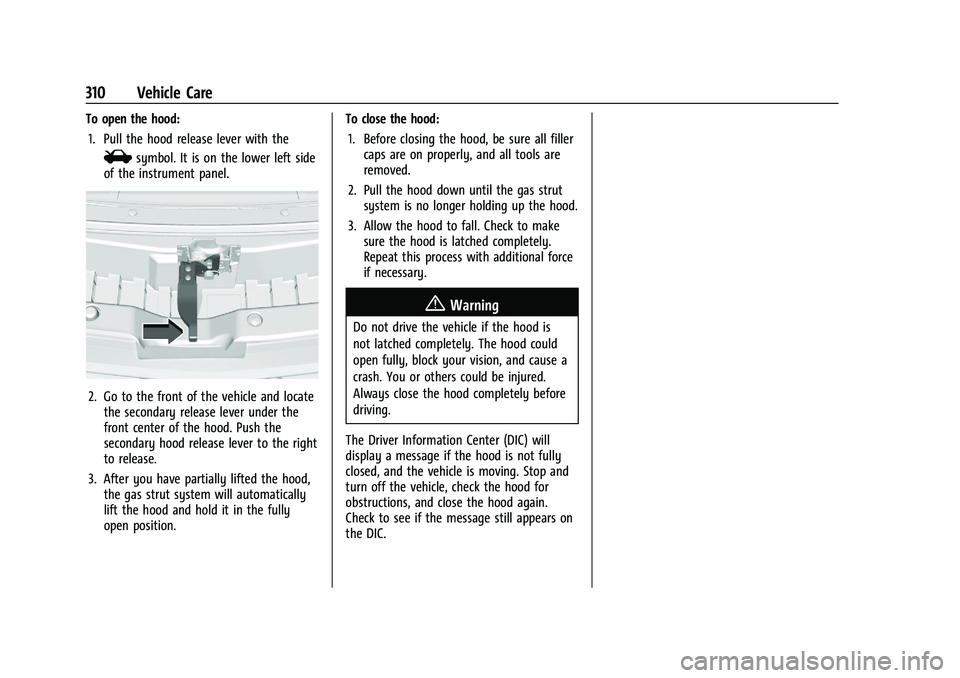
To open the hood:1. Pull the hood release lever with the
isymbol. It is on the lower left side
of the instrument panel.
2. Go to the front of the vehicle and locate the secondary release lever under the
front center of the hood. Push the
secondary hood release lever to the right
to release.
3. After you have partially lifted the hood, the gas strut system will automatically
lift the hood and hold it in the fully
open position. To close the hood:
1. Before closing the hood, be sure all filler caps are on properly, and all tools are
removed.
2. Pull the hood down until the gas strut system is no longer holding up the hood.
3. Allow the hood to fall. Check to make sure the hood is latched completely.
Repeat this process with additional force
if necessary.
{Warning
Do not drive the vehicle if the hood is
not latched completely. The hood could
open fully, block your vision, and cause a
crash. You or others could be injured.
Always close the hood completely before
driving.
The Driver Information Center (DIC) will
display a message if the hood is not fully
closed, and the vehicle is moving. Stop and
turn off the vehicle, check the hood for
obstructions, and close the hood again.
Check to see if the message still appears on
the DIC.
Page 313 of 432
GMC Yukon/Yukon XL/Denali Owner Manual (GMNA-Localizing-U.S./
Canada/Mexico-16417394) - 2023 - CRC - 4/26/22
312 Vehicle Care
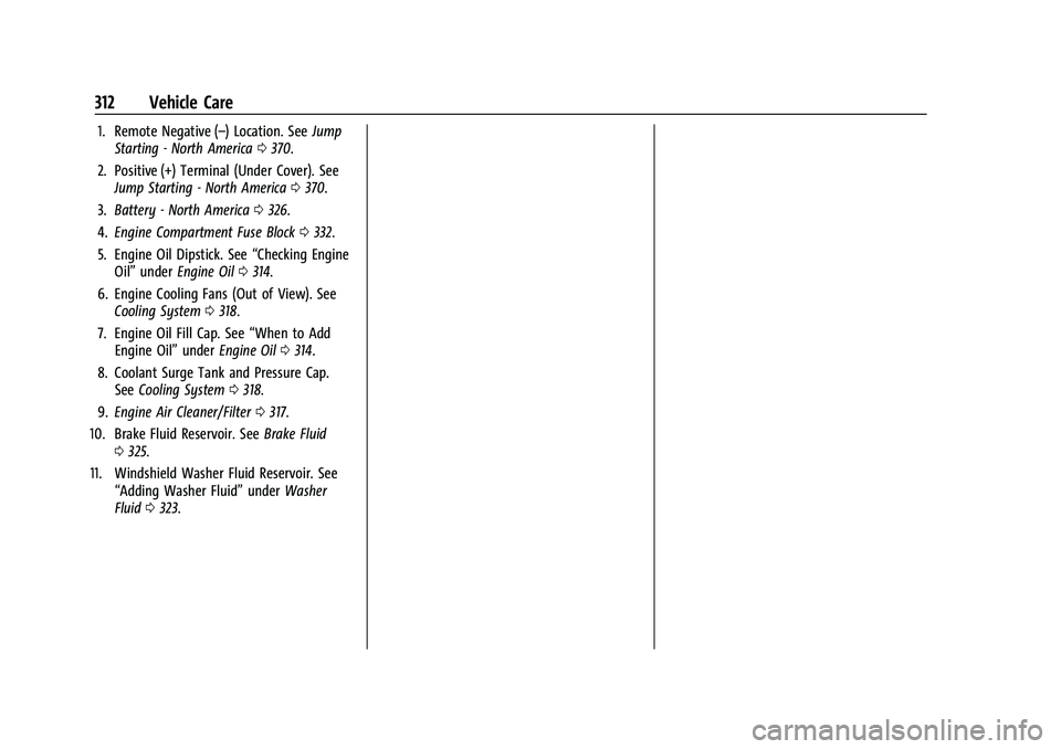
1. Remote Negative (–) Location. SeeJump
Starting - North America 0370.
2. Positive (+) Terminal (Under Cover). See Jump Starting - North America 0370.
3. Battery - North America 0326.
4. Engine Compartment Fuse Block 0332.
5. Engine Oil Dipstick. See “Checking Engine
Oil” under Engine Oil 0314.
6. Engine Cooling Fans (Out of View). See Cooling System 0318.
7. Engine Oil Fill Cap. See “When to Add
Engine Oil” underEngine Oil 0314.
8. Coolant Surge Tank and Pressure Cap. See Cooling System 0318.
9. Engine Air Cleaner/Filter 0317.
10. Brake Fluid Reservoir. See Brake Fluid
0 325.
11. Windshield Washer Fluid Reservoir. See “Adding Washer Fluid” underWasher
Fluid 0323.
Page 314 of 432
GMC Yukon/Yukon XL/Denali Owner Manual (GMNA-Localizing-U.S./
Canada/Mexico-16417394) - 2023 - CRC - 4/26/22
Vehicle Care 313
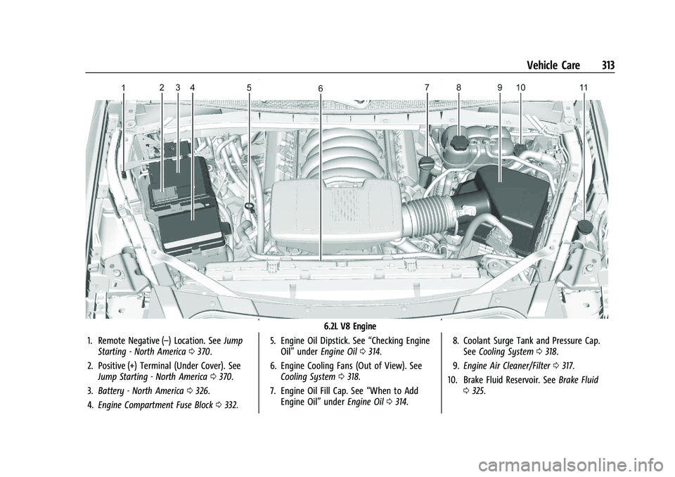
6.2L V8 Engine
1. Remote Negative (–) Location. See Jump
Starting - North America 0370.
2. Positive (+) Terminal (Under Cover). See Jump Starting - North America 0370.
3. Battery - North America 0326.
4. Engine Compartment Fuse Block 0332. 5. Engine Oil Dipstick. See
“Checking Engine
Oil” under Engine Oil 0314.
6. Engine Cooling Fans (Out of View). See Cooling System 0318.
7. Engine Oil Fill Cap. See “When to Add
Engine Oil” underEngine Oil 0314. 8. Coolant Surge Tank and Pressure Cap.
See Cooling System 0318.
9. Engine Air Cleaner/Filter 0317.
10. Brake Fluid Reservoir. See Brake Fluid
0 325.
Page 322 of 432
GMC Yukon/Yukon XL/Denali Owner Manual (GMNA-Localizing-U.S./
Canada/Mexico-16417394) - 2023 - CRC - 4/26/22
Vehicle Care 321
Caution
Failure to follow the specific coolant fill
procedure could cause the engine to
overheat and could cause system
damage. If coolant is not visible in the
surge tank, contact your dealer.
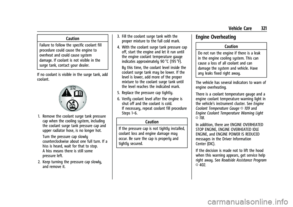
If no coolant is visible in the surge tank, add
coolant.
1. Remove the coolant surge tank pressure cap when the cooling system, including
the coolant surge tank pressure cap and
upper radiator hose, is no longer hot.
Turn the pressure cap slowly
counterclockwise about one full turn. If a
hiss is heard, wait for that to stop.
A hiss means there is still some
pressure left.
2. Keep turning the pressure cap slowly, and remove it. 3. Fill the coolant surge tank with the
proper mixture to the full cold mark.
4. With the coolant surge tank pressure cap off, start the engine and let it run until
the engine coolant temperature gauge
indicates approximately 90 °C (195 °F).
By this time, the coolant level inside the
coolant surge tank may be lower. If the
level is lower, add more of the proper
mixture to the coolant surge tank until
the level reaches the indicated mark.
5. Replace the pressure cap tightly.
6. Verify coolant level after the engine is shut off and the coolant is cold.
If necessary, repeat coolant fill procedure
Steps 1–6.
Caution
If the pressure cap is not tightly installed,
coolant loss and engine damage may
occur. Be sure the cap is properly and
tightly secured.
Engine Overheating
Caution
Do not run the engine if there is a leak
in the engine cooling system. This can
cause a loss of all coolant and can
damage the system and vehicle. Have
any leaks fixed right away.
The vehicle has several indicators to warn of
engine overheating.
There is a coolant temperature gauge and a
engine coolant temperature warning light in
the vehicle's instrument cluster. See Engine
Coolant Temperature Gauge 0109 and
Engine Coolant Temperature Warning Light
0 118.
In addition, there are ENGINE OVERHEATED
STOP ENGINE, ENGINE OVERHEATED IDLE
ENGINE, and ENGINE POWER IS REDUCED
messages in the Driver Information
Center (DIC).
If the decision is made not to lift the hood
when this warning appears, get service help
right away. See Roadside Assistance Program
0 402.