odometer GREAT WALL FLORID 2008 Service Manual
[x] Cancel search | Manufacturer: GREAT WALL, Model Year: 2008, Model line: FLORID, Model: GREAT WALL FLORID 2008Pages: 281, PDF Size: 43.97 MB
Page 24 of 281
Downloaded from www.Manualslib.com manuals search engine 17Overall Parameters
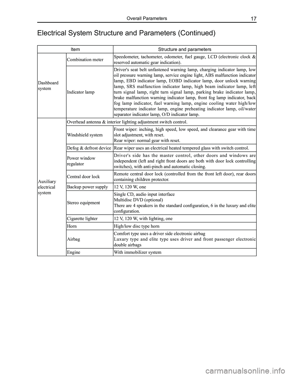
ItemStructure and parameters
Dashboard
system
Combination meter Speedometer, tachometer, odometer, fuel gauge, LCD (electronic clock &
reserved automatic gear indication).
Indicator lamp
Driver's seat belt unfastened warning lamp, charging indicator lamp, low
oil pressure warning lamp, service engine light, ABS malfunction indicator
lamp, EBD indicator lamp, EOBD indicator lamp, door unlock warning
lamp, SRS malfunction indicator lamp, high beam indicator lamp, left
turn signal lamp, right turn signal lamp, parking brake indicator lamp,
brake malfunction warning indicator lamp, front fog lamp indicator, back
fog lamp indicator, fuel warning lamp, engine cooling water high/low
temperature indicator lamp, engine preheating indicator lamp, oil/water
separator indicator lamp, O/D indicator lamp.
Auxiliary
electrical
system
Overhead antenna & interior lighting adjustment switch control.
Windshield system
Front wiper: inching, high speed, low speed, and clearance gear with time
slot adjustment, with reset.
Rear wiper: normal gear with reset.
Defog & defrost deviceRear wiper uses an electrical heated tempered glass with switch control.\
Power window
regulator
D r i v e r ' s s i d e h a s t h e m a s t e r c o n t r o l , o t h e r d o o r s a n d w i n d o w s a r e
independent (left and right front doors are both with door lock controlling
switches), with anti-pinch and automatic closing.
Central door lockRemote central door lock (controlled from the front left door), rear doors
containing children protector.
Backup power supply12 V, 120 W, one
Stereo equipment
Single CD, audio input interface
Multidisc DVD (optional)
There are 4 speakers in the standard configuration, 6 in the luxury and elite
configuration.
Cigarette lighter12 V, 120 W, with lighting, one
HornHigh/low disc type horn
Airbag
Comfort type uses a driver side electronic airbag
Luxury type and elite type uses driver and front passenger electronic
double airbags
EngineWith immobilizer system
Electrical System Structure and Parameters (Continued)
Page 50 of 281
Downloaded from www.Manualslib.com manuals search engine 43Transmission
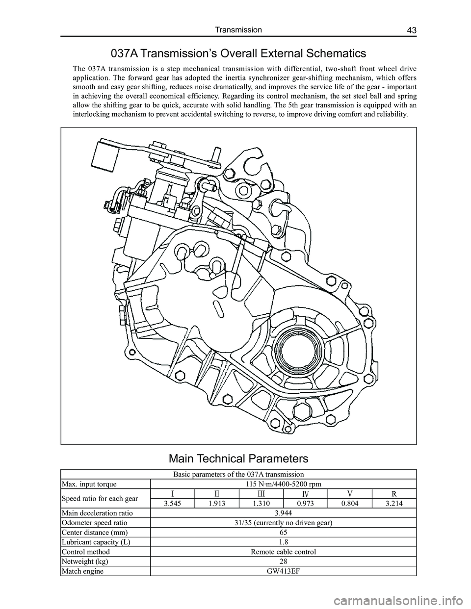
Main Technical Parameters
Basic parameters of the 037A transmission
Max. input torque115 N·m/4400-5200 rpm
Speed ratio for each gear3.5451.9131.3100.9730.8043.214
Main deceleration ratio3.944
Odometer speed ratio31/35 (currently no driven gear)
Center distance (mm)65
Lubricant capacity (L)1.8
Control methodRemote cable control
Netweight (kg)28
Match engineGW413EF
037A Transmission’s Overall External Schematics
The 037A transmission is a step mechanical transmission with differential, two-shaft front wheel drive
application. The forward gear has adopted the inertia synchronizer gear-shifting mechanism, which offers
smooth and easy gear shifting, reduces noise dramatically, and improves the service life of the gear - important
in achieving the overall economical efficiency. Regarding its control mechanism, the set steel ball and spring
allow the shifting gear to be quick, accurate with solid handling. The 5th gear transmission is equipped with an
interlocking mechanism to prevent accidental switching to reverse, to im\
prove driving comfort and reliability.
Page 54 of 281
Downloaded from www.Manualslib.com manuals search engine 47Transmission
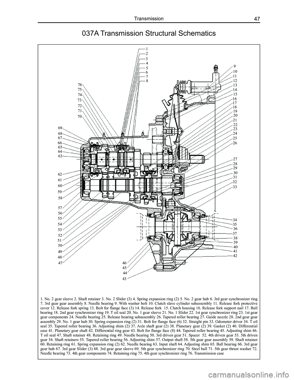
1. No. 2 gear sleeve 2. Shaft retainer 3. No. 2 Slider (3) 4. Spring expansion ring (2) 5. No. 2 gear hub 6. 3rd gear synchronizer ring 7. 3rd gear gear assembly 8. Needle bearing 9. With washer bolt 10. Clutch slave cylinder subassembly 11. Release fork protective cover 12. Release fork spring 13. Bolt for flange face (3) 14. Release fork 15. Clutch housing 16. Release fork support nail 17. Ball bearing 18. 2nd gear synchronizer ring 19. T oil seal 20. No. 1 gear sleeve 21. No. 1 Slider 22. 1st gear synchronizer ring 23. 1st gear gear components 24. Needle bearing 25. Release bearing subassembly 26. Tapered roller bearing 27. Guide nozzle 28. 2nd gear gear
assembly 29. No. 1 gear hub 30. Spring expansion ring (2) 31. Bolt for flange face (6) 32. Straight pin 33. Odometer driver 34. T oil seal 35. Tapered roller bearing 36. Adjusting shim (2) 37. Axle shaft gear (2) 38. Planetary gear (2) 39. Gasket (2) 40. Differential case 41. Planetary gear shaft 42. Differential ring gear 43. Bolt for flange face (8) 44. Tapered roller bearing 45. Adjusting shim 46. T oil seal 47. Shaft retainer 48. Retaining ring 49. Needle bearing 50. 3rd driven gear 51. Spacer 52. 4th driven gear 53. 5th driven gear 54. Shaft retainers 55. Tapered roller bearing 56. Adjusting shim 57. Output shaft 58. 5th gear gear assembly 59. Shaft retainer 60. Retaining ring 61. Spring expansion ring (2) 62. Needle bearing 63. Input shaft 64. Adjusting shim 65. Ball bearing 66. 3rd gear gear hub 67. 3rd gear Slider (3) 68. 3rd gear gear sleeve 69. 5th gear synchronizer ring 70. Steel ball 71. 5th gear thrust washer 72. Needle bearing 73. 4th gear components 74. Retaining ring 75. 4th gear synchronizer ring 76. Transmission case
037A Transmission Structural Schematics
1
2
34
567
9
8
10
111213
1415
1617181920
21
222324
25
26
27
2829
3031
32
33
343536
37
3839
4041
42
43
44
45
4647
48
49
50
51
52
53
54
55
59
56
57
58
60
61
62
63646566
6768
69
70
71
72
73
74
75
76
Page 75 of 281
Downloaded from www.Manualslib.com manuals search engine GWFLORID Maintenance Manual68
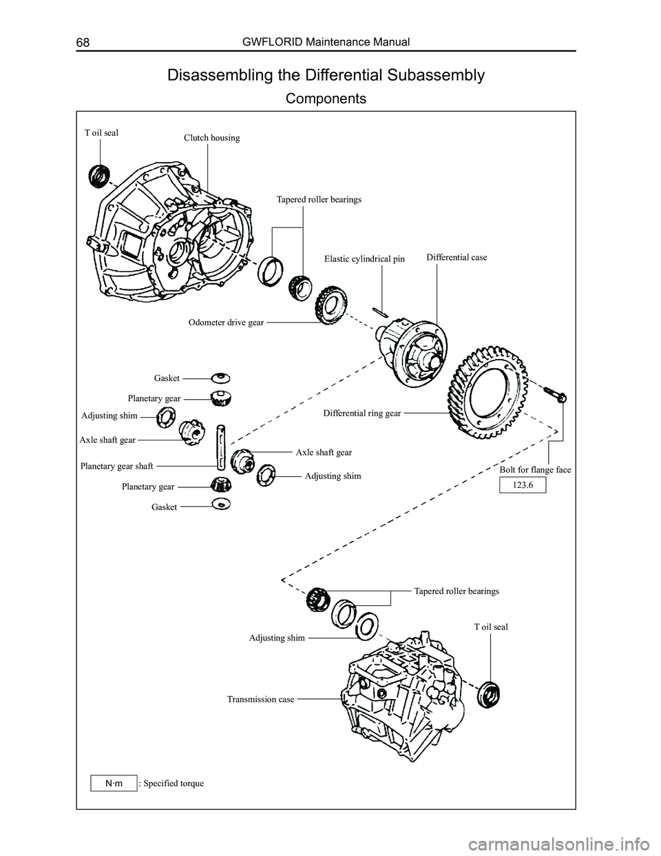
Disassembling the Differential Subassembly
Components
T oil sealClutch housing
Tapered roller bearings
Elastic cylindrical pin
Odometer drive gear
Differential case
Differential ring gear
Bolt for flange face
Gasket
Planetary gear
Adjusting shim
Axle shaft gear
Planetary gear shaft
Planetary gear
Gasket
Axle shaft gear
Adjusting shim
Tapered roller bearings
Transmission case
Adjusting shim
T oil seal
123.6
: Specified torqueN·m
Page 76 of 281
Downloaded from www.Manualslib.com manuals search engine 69Transmission
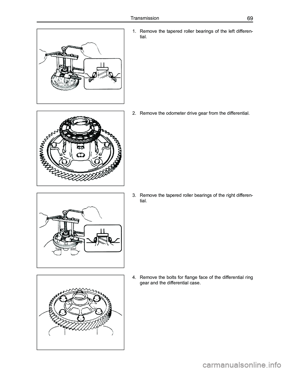
1. Remove the tapered roller bearings of the left differen-
tial.
2. Remove the odometer drive gear from the differential.
3. Remove the tapered roller bearings of the right differen-
tial.
4. Remove the bolts for flange face of the differential ring
gear and the differential case.
Page 96 of 281
Downloaded from www.Manualslib.com manuals search engine 89Suspension System
Wheel and Tire
Tire
Remark
This vehicle's tire is of the tubeless type. The optimal design condition is met when the inflation pressure is at
the recommended value, and the tire is under full load. Maintaining suitable tire pressure and proper driving
habits greatly influence the tire's use life. For the vehicle, it improves riding comfort, stability, and handling. For
the tire, it reduces tread wear, damage to the tire and extends tire life. Overloading, speeding, and unnecessary
emergency braking will all add to the tire's wear and tear.
Tire pressure measurements should be taken under normal temperature. If the tire pressure rises due to motion
generated heat when driving, cooling it will return to the normal temperature. Therefore, do not deflate the tire
when the air pressure has risen to this point. The tire's air pressure will naturally and slowly decrease when used
under normal conditions. Hence please inspect the air pressure regularly (suggested once a month). The spare
tire should be kept in a useable condition at all times.
Inspect the tire pressure when it is cool monthly or before a long drive. Adjust the tire pressure to the recom-
mended level. The air pressure will normally rise because the tire warms up due to movement. Therefore, after
driving, you absolutely must not deflate or reduce the tire's air pressure, as deflating could reduce the cool tire's
air pressure.
Tire inflation
During a new tire's initial stage of use, warning due to bending motions will cause the tire to swell, and thus
reduce the corresponding air pressure. After 24 hours or 2000-3000 km worth of drive, charge the air pressure.
After inflating, check if the air nozzle core is leaking air with soapy \
water, then lock on the cap.
Possible problems caused by tire pressure
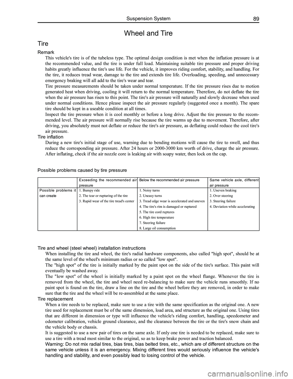
Exceeding the recommended air
pressure
Below the recommended air pressureSame vehicle axle, different
air pressure
Possible problems it
can create
1. Bumpy ride
2. The tear or rupturing of the tire
3. Rapid wear of the tire tread's center
1. Noisy turns
2. Uneasy turns
3. Tread edge wear is accelerated and uneven
4. The tire's rim is damaged or ruptured
5. The tire cord ruptures
6. High tire temperature
7. Steering failure
8. Large oil consumption
1. Uneven braking
2. Over steering
3. Steering failure
4. Deviation while accelerating
Tire and wheel (steel wheel) installation instructions
When installing the tire and wheel, the tire's radial hardware components, also called "high spot", should be at
the same level of the wheel's minimum radius or so called "low spot".
The "high spot" of the tire is initially marked by the paint spot on the side of the tire's surface. This paint will
eventually be washed away.
The "low spot" of the wheel is initially marked by a paint spot on the wheel flange. Whenever the tire is
removed from the wheel, the tire and wheel need re-balancing to make sure the vehicle runs smoothly. If no
paint spot is found on the tire, draw a line on the tire and the wheel before they are removed, in order to make
sure that the tire and the wheel will be re-assembled at the same place.\
Tire replacement
When a tire needs to be replaced, make sure to use a tire with the same specification as the original one. A new
tire used for replacement must be of the same dimension, load area, and structure as the original one. Using tires
that are different in dimension or type will influence the vehicle's riding comfort, handling, speedometer and
odometer calibration, vehicle ground clearance, and the clearance between the tire or the tire's snow chain and
the vehicle body or chassis.
It is suggested to use a new pair of tires on the same axle. If only one tire is needed to be replaced, make sure to
use a tire with a tread most similar to the original, so as to keep brak\
e power and traction balanced.
Warning: Do not mix radial tires, bias tires, bias belted tires, etc., which are of different structure on the
same vehicle unless it is an emergency. Mixing different tires would seriously influence the vehicle's
handling and stability, and even possibly lead to losing control of the vehicle.
Page 100 of 281
Downloaded from www.Manualslib.com manuals search engine 93Suspension System
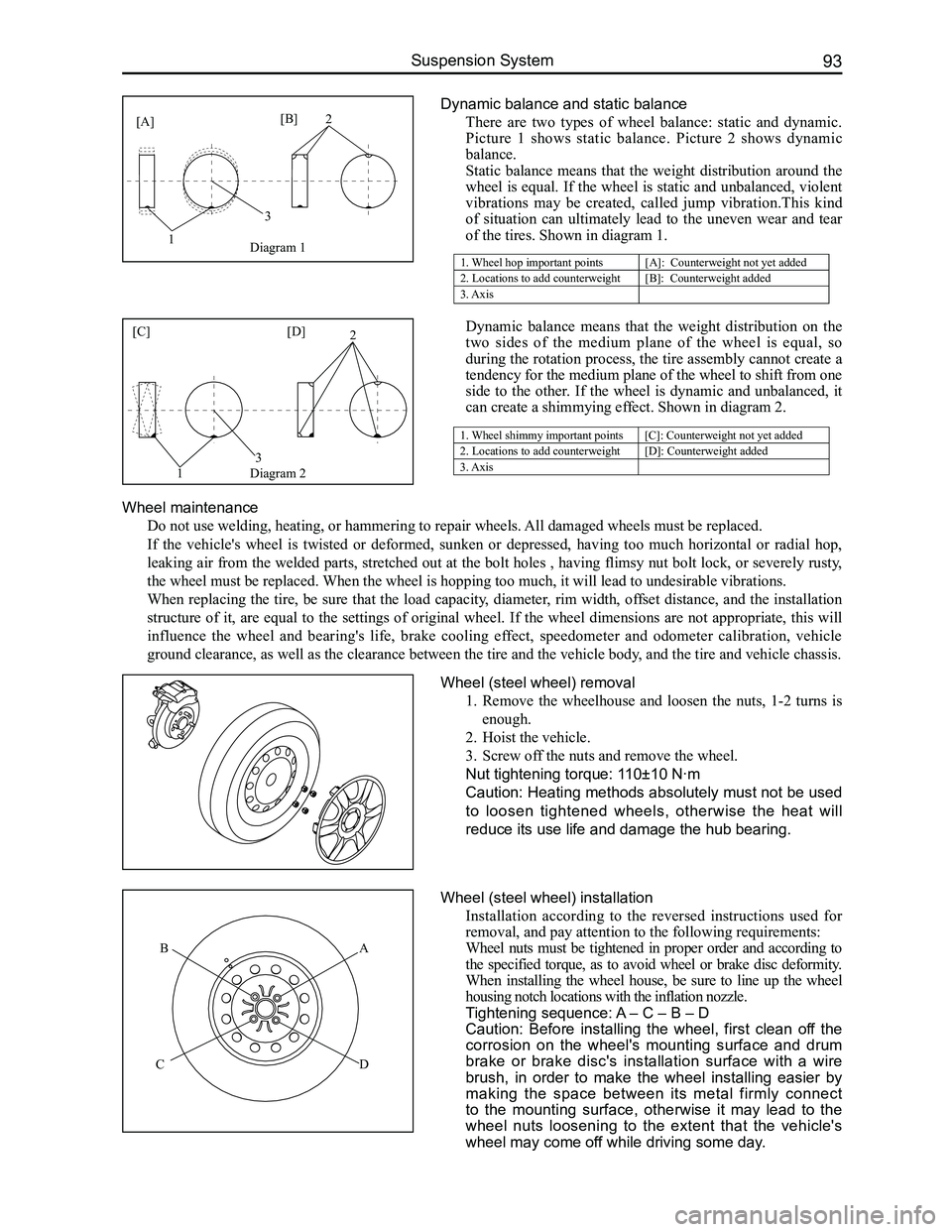
Dynamic balance and static balance
There are two types of wheel balance: static and dynamic.
Picture 1 shows static balance. Picture 2 shows dynamic
balance.
Static balance means that the weight distribution around the
wheel is equal. If the wheel is static and unbalanced, violent
vibrations may be created, called jump vibration.This kind
of situation can ultimately lead to the uneven wear and tear
of the tires. Shown in diagram 1.
Dynamic balance means that the weight distribution on the
two sides of the medium plane of the wheel is equal, so
during the rotation process, the tire assembly cannot create a
tendency for the medium plane of the wheel to shift from one
side to the other. If the wheel is dynamic and unbalanced, it
can create a shimmying effect. Shown in diagram 2.
1. Wheel shimmy important points[C]: Counterweight not yet added
2. Locations to add counterweight[D]: Counterweight added
3. Axis
Wheel maintenance
Do not use welding, heating, or hammering to repair wheels. All damaged wheels must be replaced.
If the vehicle's wheel is twisted or deformed, sunken or depressed, having too much horizontal or radial hop,
leaking air from the welded parts, stretched out at the bolt holes , having flimsy nut bolt lock, or severely rusty,
the wheel must be replaced. When the wheel is hopping too much, it will lead to undesirable vibratio\
ns.
When replacing the tire, be sure that the load capacity, diameter, rim width, offset distance, and the installation
structure of it, are equal to the settings of original wheel. If the wheel dimensions are not appropriate, this will
influence the wheel and bearing's life, brake cooling effect, speedometer and odometer calibration, vehicle
ground clearance, as well as the clearance between the tire and the vehi\
cle body, and the tire and vehicle chassis.
Wheel (steel wheel) removal
1. Remove the wheelhouse and loosen the nuts, 1-2 turns is
enough.
2. Hoist the vehicle.
3. Screw off the nuts and remove the wheel.
Nut tightening torque: 110±10 N·m
Caution: Heating methods absolutely must not be used
to loosen tightened wheels, otherwise the heat will
reduce its use life and damage the hub bearing.
Wheel (steel wheel) installation
Installation according to the reversed instructions used for
removal, and pay attention to the following requirements:
Wheel nuts must be tightened in proper order and according to
the specified torque, as to avoid wheel or brake disc deformity.
When installing the wheel house, be sure to line up the wheel
housing notch locations with the inflation nozzle.
Tightening sequence: A – C – B – D
Caution: Before installing the wheel, first clean off the
corrosion on the wheel's mounting surface and drum
brake or brake disc's installation surface with a wire
brush, in order to make the wheel installing easier by
making the space between its metal firmly connect
to the mounting surface, otherwise it may lead to the
wheel nuts loosening to the extent that the vehicle's
wheel may come off while driving some day.
1
3
2[A][B]
1. Wheel hop important points[A]: Counterweight not yet added
2. Locations to add counterweight[B]: Counterweight added
3. Axis
Diagram 1
Diagram 2
[C][D]
1
3
2
AB
CD
Page 176 of 281
Downloaded from www.Manualslib.com manuals search engine 169Vehicle Body Electronic System
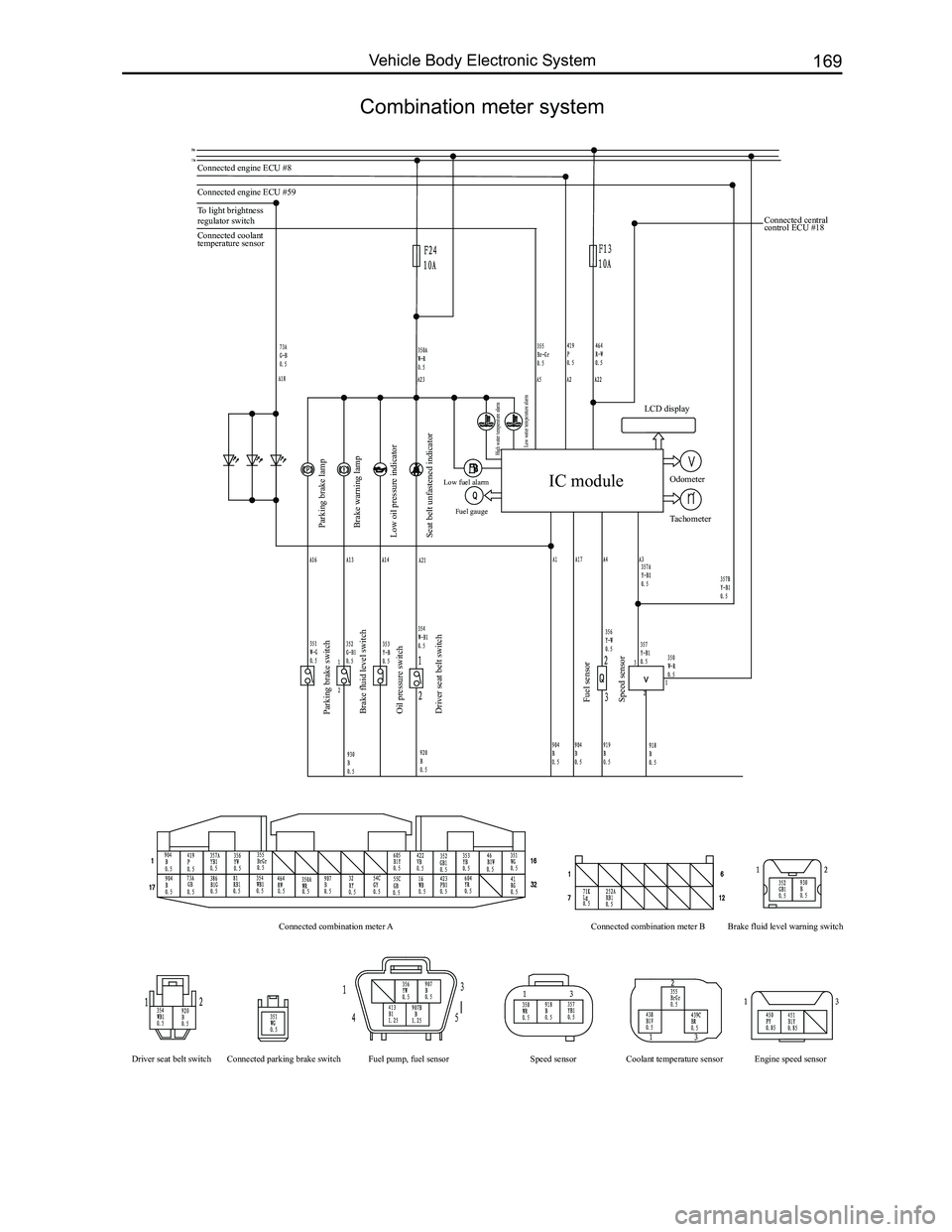
Combination meter system
Connected engine ECU #8
Connected engine ECU #59
To light brightness
regulator switch
Parking brake lamp
Parking brake switch
Brake fluid level switch
Oil pressure switch
Driver seat belt switch
Fuel sensor
Speed sensor
Connected combination meter A
Driver seat belt switch Connected parking brake switch Fuel pump, fuel sensor Coolant temperature sensor Engine speed sensor
Speed sensor Connected combination meter B
Brake fluid level warning switch
Brake warning lamp
Low oil pressure indicator
Seat belt unfastened indicator
Low fuel alarm Fuel gauge
High water temperature alarm
Low water temperature alarm
Connected coolant
temperature sensor Connected central
control ECU #18
IC module
LCD display
Odometer
Tachometer