oil type GREAT WALL FLORID 2008 Service Manual
[x] Cancel search | Manufacturer: GREAT WALL, Model Year: 2008, Model line: FLORID, Model: GREAT WALL FLORID 2008Pages: 281, PDF Size: 43.97 MB
Page 11 of 281
Downloaded from www.Manualslib.com manuals search engine GWFLORID Maintenance Manual4
Comprehensive Repair Instructions
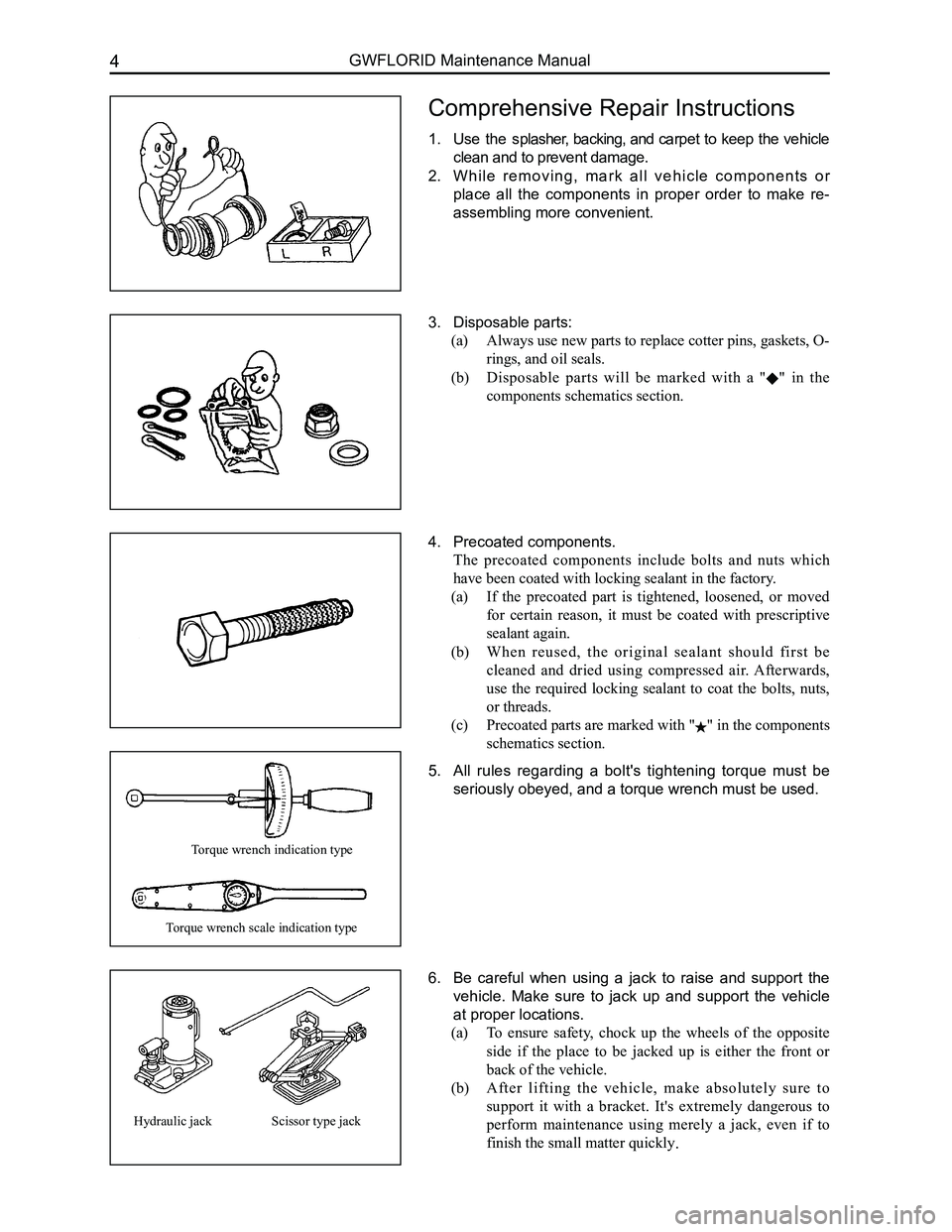
1. Use the splasher, backing, and carpet to keep the vehicle
clean and to prevent damage.
2. W h i l e r e m o v i n g , m a r k a l l v e h i c l e c o m p o n e n t s o r
place all the components in proper order to make re-
assembling more convenient.
3. Disposable parts:
(a) Always use new parts to replace cotter pins, gaskets, O-
rings, and oil seals.
(b) Disposable parts will be marked with a "" in the
components schematics section.
4. Precoated components.
The precoated components include bolts and nuts which
have been coated with locking sealant in the factory.
(a) If the precoated part is tightened, loosened, or moved
for certain reason, it must be coated with prescriptive
sealant again.
(b) When reused, the original sealant should first be
cleaned and dried using compressed air. Afterwards,
use the required locking sealant to coat the bolts, nuts,
or threads.
(c) Precoated parts are marked with "" in the components
schematics section.
5. All rules regarding a bolt's tightening torque must be
seriously obeyed, and a torque wrench must be used.
6. Be careful when using a jack to raise and support the
vehicle. Make sure to jack up and support the vehicle
at proper locations.
(a) To ensure safety, chock up the wheels of the opposite
side if the place to be jacked up is either the front or
back of the vehicle.
(b) After lifting the vehicle, make absolutely sure to
support it with a bracket. It's extremely dangerous to
perform maintenance using merely a jack, even if to
finish the small matter quickly.
Torque wrench indication type
Torque wrench scale indication type
Hydraulic jackScissor type jack
Page 16 of 281
Downloaded from www.Manualslib.com manuals search engine 9Overview
General Repair Methods and Operations
1. If a jack is needed, please kindly comply to the safety procedures liste\
d below.
2. Park the vehicle on a flat surface, stablize the front and the back wheels using any fixed object or tool,
jack up the vehicle, support it with the chassis, and then start the mai\
ntenance.
3. Disconnect the battery's negative cable before maintenance, in order to reduce the possibility of
damaging and burning out the cable due to a short circuit.
4. Cover the vehicle body, seats, and floor to prevent them from being damaged and polluted.
5. Handle brake fluid and antifreeze fluid carefully, because it may damage the vehicle's surface paint
and its surroundings.
6. Using the proper tools or basic tools that have been recommended and are purchasable is very
important in guaranteeing an effective and reliable maintenance result.
7. Dispose the used dowel pins, gaskets, O-rings, oil seals, lock washers, and self-locking nuts. Prepare
new parts for installation. Normal functions are not guaranteed if these\
parts are reused.
8. Store the removed parts in order and in groups to make reassembly more c\
onvenient.
9. Store bolts and nuts separately, because their hardness levels and designs are different according to
the installation locations.
10. Clean parts before they are inspected or reassembled. In addition, parts that come in contact with
engine oil also need to be cleaned, as well as checked for blockage by u\
sing compressed air.
11. Before installation, use engine oil or grease to lubricate the rotating and sliding sides of the necessary
parts.
12. When necessary, use sealant on gaskets to avoid leakage.
13. Please carefully comply to all tightening torque specifications of b\
olts and nuts.
14. After maintenance, check to make sure whether the repairs were performed correctly and whether the
malfunctions have been fixed.
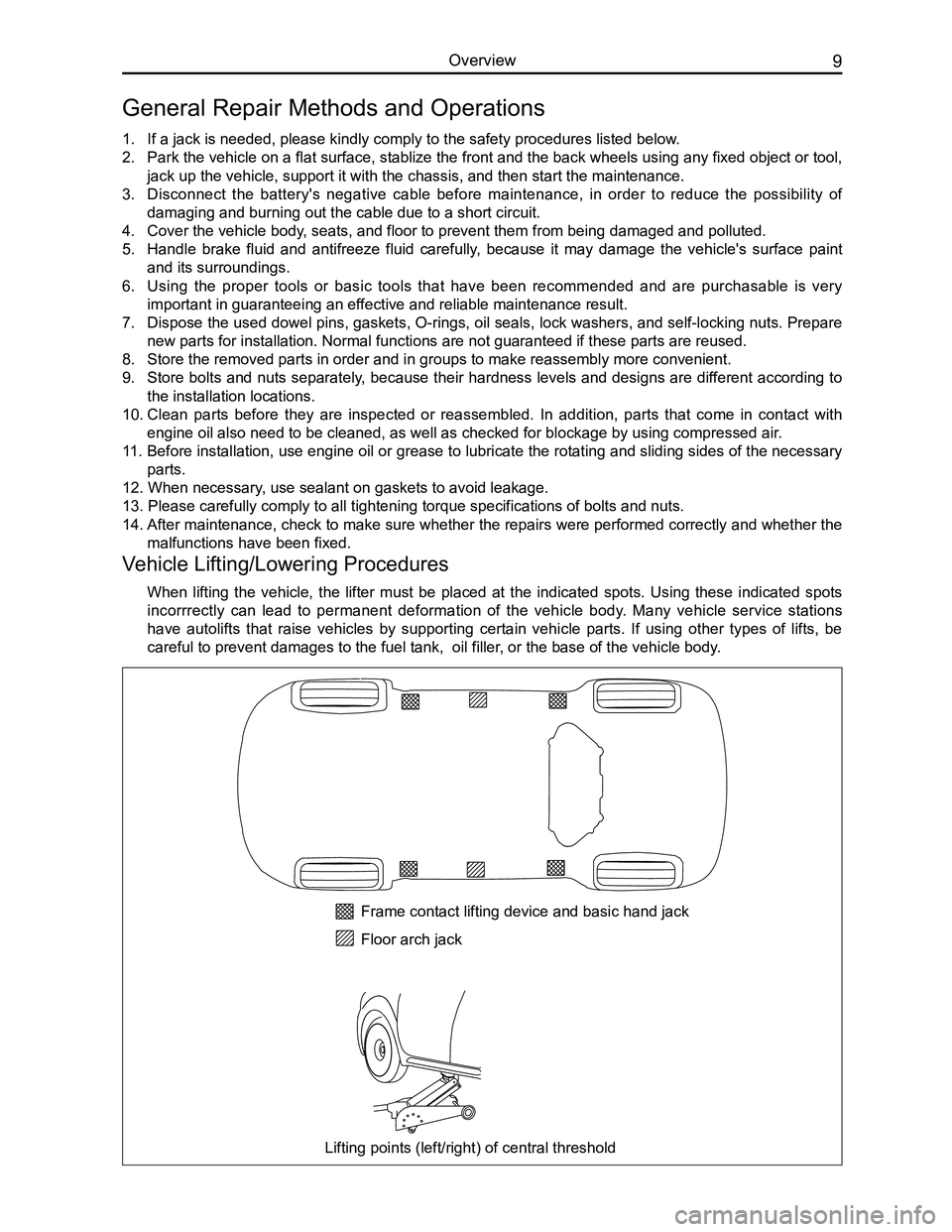
Vehicle Lifting/Lowering Procedures
When lifting the vehicle, the lifter must be placed at the indicated spots. Using these indicated spots
incorrrectly can lead to permanent deformation of the vehicle body. Many vehicle service stations
have autolifts that raise vehicles by supporting certain vehicle parts. If using other types of lifts, be
careful to prevent damages to the fuel tank, oil filler, or the base of the vehicle body.
Frame contact lifting device and basic hand jack
Floor arch jack
Lifting points (left/right) of central threshold
Page 24 of 281
Downloaded from www.Manualslib.com manuals search engine 17Overall Parameters
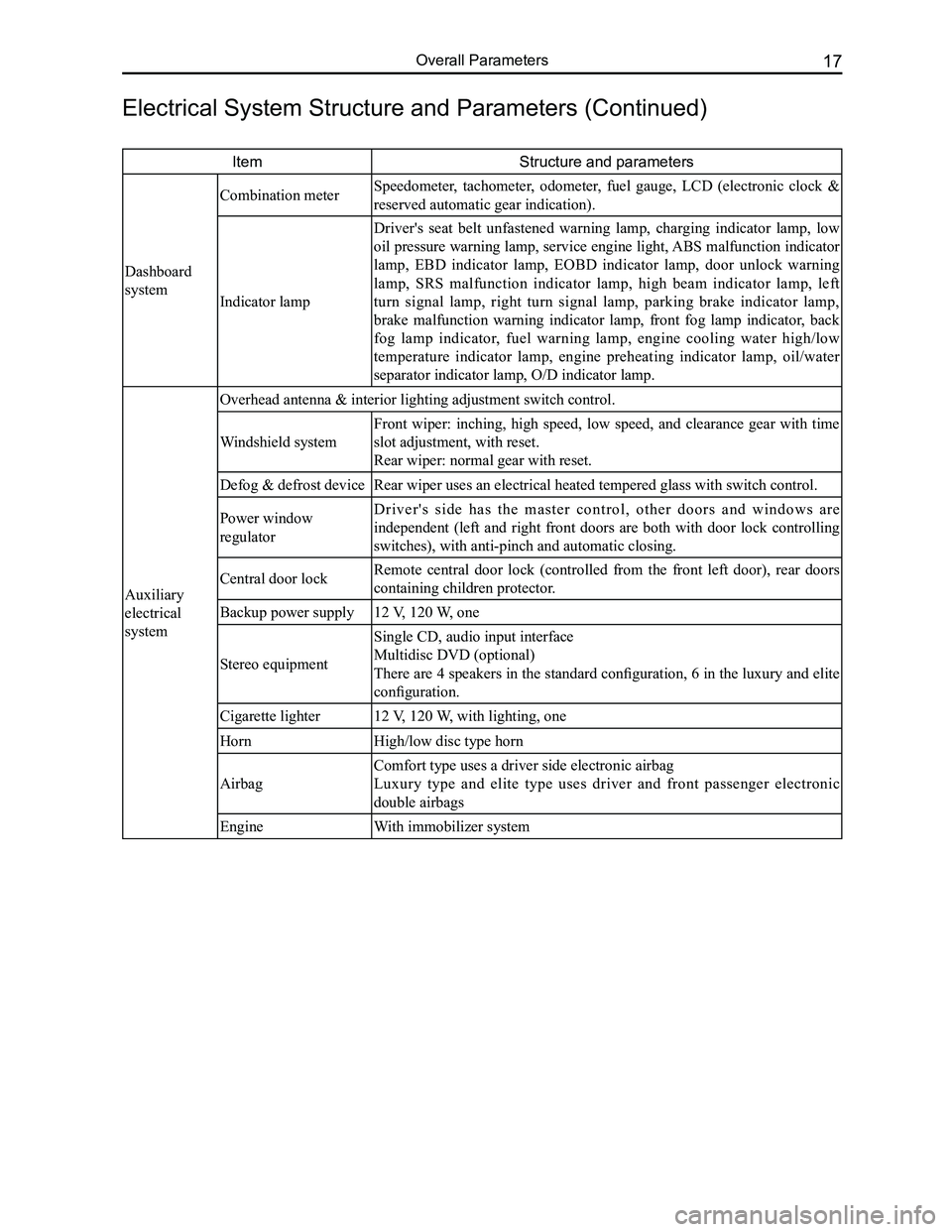
ItemStructure and parameters
Dashboard
system
Combination meter Speedometer, tachometer, odometer, fuel gauge, LCD (electronic clock &
reserved automatic gear indication).
Indicator lamp
Driver's seat belt unfastened warning lamp, charging indicator lamp, low
oil pressure warning lamp, service engine light, ABS malfunction indicator
lamp, EBD indicator lamp, EOBD indicator lamp, door unlock warning
lamp, SRS malfunction indicator lamp, high beam indicator lamp, left
turn signal lamp, right turn signal lamp, parking brake indicator lamp,
brake malfunction warning indicator lamp, front fog lamp indicator, back
fog lamp indicator, fuel warning lamp, engine cooling water high/low
temperature indicator lamp, engine preheating indicator lamp, oil/water
separator indicator lamp, O/D indicator lamp.
Auxiliary
electrical
system
Overhead antenna & interior lighting adjustment switch control.
Windshield system
Front wiper: inching, high speed, low speed, and clearance gear with time
slot adjustment, with reset.
Rear wiper: normal gear with reset.
Defog & defrost deviceRear wiper uses an electrical heated tempered glass with switch control.\
Power window
regulator
D r i v e r ' s s i d e h a s t h e m a s t e r c o n t r o l , o t h e r d o o r s a n d w i n d o w s a r e
independent (left and right front doors are both with door lock controlling
switches), with anti-pinch and automatic closing.
Central door lockRemote central door lock (controlled from the front left door), rear doors
containing children protector.
Backup power supply12 V, 120 W, one
Stereo equipment
Single CD, audio input interface
Multidisc DVD (optional)
There are 4 speakers in the standard configuration, 6 in the luxury and elite
configuration.
Cigarette lighter12 V, 120 W, with lighting, one
HornHigh/low disc type horn
Airbag
Comfort type uses a driver side electronic airbag
Luxury type and elite type uses driver and front passenger electronic
double airbags
EngineWith immobilizer system
Electrical System Structure and Parameters (Continued)
Page 79 of 281
Downloaded from www.Manualslib.com manuals search engine GWFLORID Maintenance Manual72
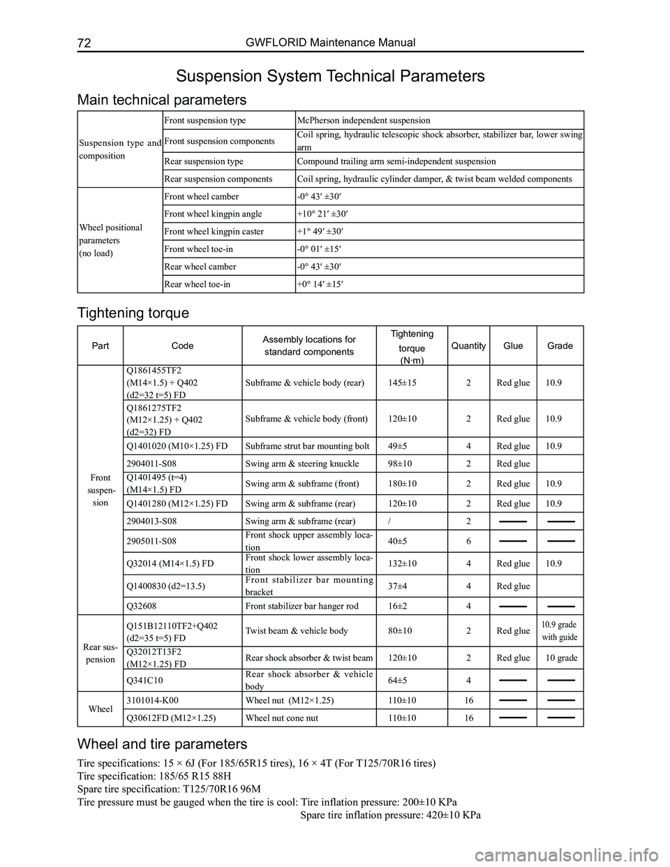
Suspension System Technical Parameters
Main technical parameters
Suspension type and
composition
Front suspension typeMcPherson independent suspension
Front suspension componentsCoil spring, hydraulic telescopic shock absorber, stabilizer bar, lower swing
arm
Rear suspension typeCompound trailing arm semi-independent suspension
Rear suspension componentsCoil spring, hydraulic cylinder damper, & twist beam welded components
Wheel positional
parameters
(no load)
Front wheel camber-0° 43′ ±30′
Front wheel kingpin angle+10° 21′ ±30′
Front wheel kingpin caster+1° 49′ ±30′
Front wheel toe-in-0° 01′ ±15′
Rear wheel camber-0° 43′ ±30′
Rear wheel toe-in+0° 14′ ±15′
Wheel and tire parameters
Tire specifications: 15 × 6J (For 185/65R15 tires), 16 × 4T (For T125/70R16 tires)
Tire specification: 185/65 R15 88H
Spare tire specification: T125/70R16 96M
Tire pressure must be gauged when the tire is cool: Tire inflation pressure: 200±10 KPa
Spare tir e inflation pressure: 420±10 KPa
Tightening torque
PartCodeAssembly locations for
standard components
Tightening
torque
(N·m)
QuantityGlueGrade
Front
suspen-
sion
Q1861455TF2
(M14×1.5) + Q402
(d2=32 t=5) FD
Subframe & vehicle body (rear)145±15 2Red glue10.9
Q1861275TF2
(M12×1.25) + Q402
(d2=32) FD
Subframe & vehicle body (front)120±102Red glue10.9
Q1401020 (M10×1.25) FDSubframe strut bar mounting bolt49±54Red glue10.9
2904011-S08Swing arm & steering knuckle98±102Red glue
Q1401495 (t=4)
(M14×1.5) FDSwing arm & subframe (front)180±102Red glue10.9
Q1401280 (M12×1.25) FDSwing arm & subframe (rear)120±102Red glue10.9
2904013-S08Swing arm & subframe (rear)/2
2905011-S08Front shock upper assembly loca-
tion40±56
Q32014 (M14×1.5) FDFront shock lower assembly loca-
tion132±104Red glue10.9
Q1400830 (d2=13.5)F r o n t s t a b i l i z e r b a r m o u n t i n g
bracket37±44Red glue
Q32608Front stabilizer bar hanger rod16±24
Rear sus-
pension
Q151B12110TF2+Q402
(d2=35 t=5) FDTwist beam & vehicle body80±102Red glue10.9 grade
with guide
Q32012T13F2
(M12×1.25) FDRear shock absorber & twist beam120±102Red glue10 grade
Q341C10Rear shock absorber & vehicle
body64±54
Wheel3101014-K00Wheel nut (M12×1.25)110±1016
Q30612FD (M12×1.25)Wheel nut cone nut110±1016
Page 96 of 281
Downloaded from www.Manualslib.com manuals search engine 89Suspension System
Wheel and Tire
Tire
Remark
This vehicle's tire is of the tubeless type. The optimal design condition is met when the inflation pressure is at
the recommended value, and the tire is under full load. Maintaining suitable tire pressure and proper driving
habits greatly influence the tire's use life. For the vehicle, it improves riding comfort, stability, and handling. For
the tire, it reduces tread wear, damage to the tire and extends tire life. Overloading, speeding, and unnecessary
emergency braking will all add to the tire's wear and tear.
Tire pressure measurements should be taken under normal temperature. If the tire pressure rises due to motion
generated heat when driving, cooling it will return to the normal temperature. Therefore, do not deflate the tire
when the air pressure has risen to this point. The tire's air pressure will naturally and slowly decrease when used
under normal conditions. Hence please inspect the air pressure regularly (suggested once a month). The spare
tire should be kept in a useable condition at all times.
Inspect the tire pressure when it is cool monthly or before a long drive. Adjust the tire pressure to the recom-
mended level. The air pressure will normally rise because the tire warms up due to movement. Therefore, after
driving, you absolutely must not deflate or reduce the tire's air pressure, as deflating could reduce the cool tire's
air pressure.
Tire inflation
During a new tire's initial stage of use, warning due to bending motions will cause the tire to swell, and thus
reduce the corresponding air pressure. After 24 hours or 2000-3000 km worth of drive, charge the air pressure.
After inflating, check if the air nozzle core is leaking air with soapy \
water, then lock on the cap.
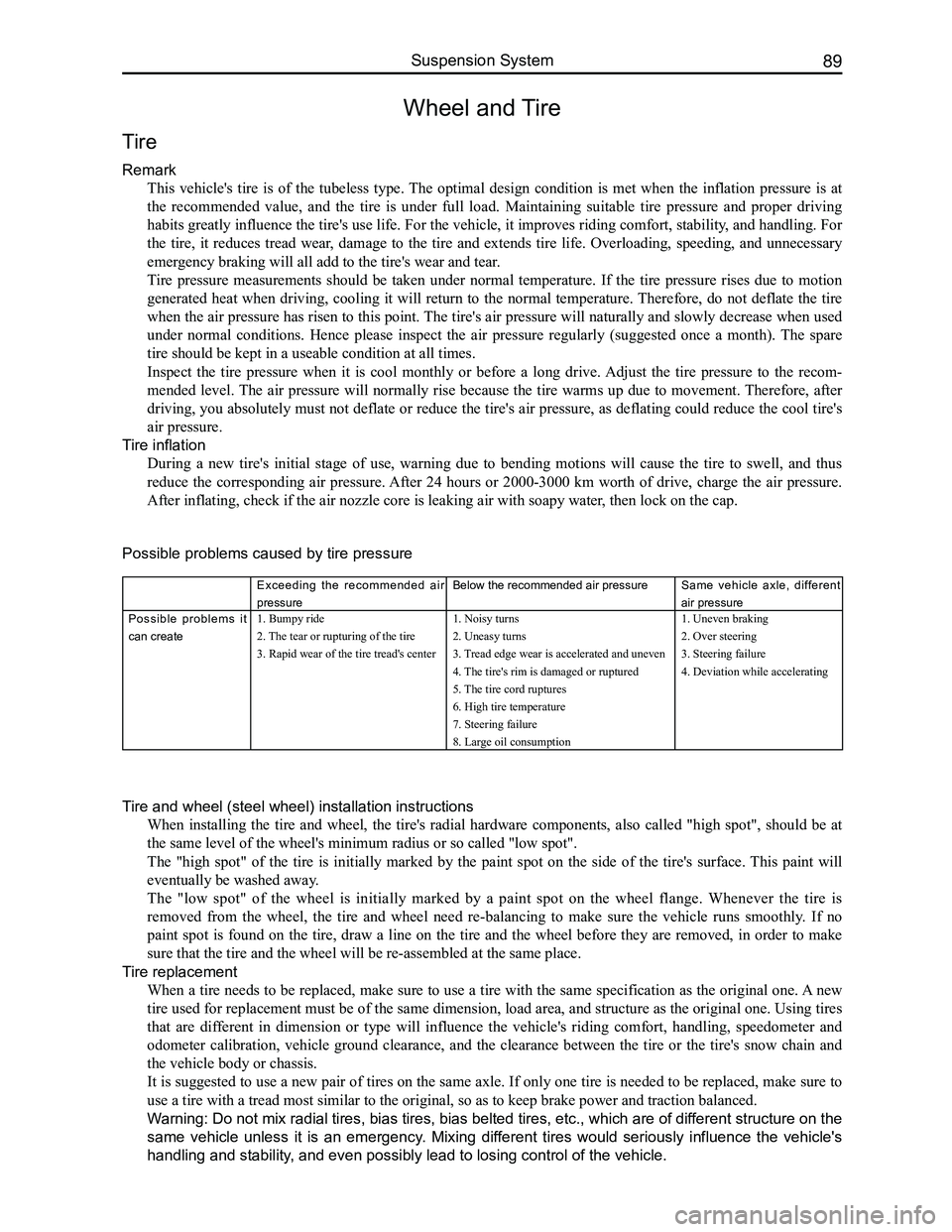
Possible problems caused by tire pressure
Exceeding the recommended air
pressure
Below the recommended air pressureSame vehicle axle, different
air pressure
Possible problems it
can create
1. Bumpy ride
2. The tear or rupturing of the tire
3. Rapid wear of the tire tread's center
1. Noisy turns
2. Uneasy turns
3. Tread edge wear is accelerated and uneven
4. The tire's rim is damaged or ruptured
5. The tire cord ruptures
6. High tire temperature
7. Steering failure
8. Large oil consumption
1. Uneven braking
2. Over steering
3. Steering failure
4. Deviation while accelerating
Tire and wheel (steel wheel) installation instructions
When installing the tire and wheel, the tire's radial hardware components, also called "high spot", should be at
the same level of the wheel's minimum radius or so called "low spot".
The "high spot" of the tire is initially marked by the paint spot on the side of the tire's surface. This paint will
eventually be washed away.
The "low spot" of the wheel is initially marked by a paint spot on the wheel flange. Whenever the tire is
removed from the wheel, the tire and wheel need re-balancing to make sure the vehicle runs smoothly. If no
paint spot is found on the tire, draw a line on the tire and the wheel before they are removed, in order to make
sure that the tire and the wheel will be re-assembled at the same place.\
Tire replacement
When a tire needs to be replaced, make sure to use a tire with the same specification as the original one. A new
tire used for replacement must be of the same dimension, load area, and structure as the original one. Using tires
that are different in dimension or type will influence the vehicle's riding comfort, handling, speedometer and
odometer calibration, vehicle ground clearance, and the clearance between the tire or the tire's snow chain and
the vehicle body or chassis.
It is suggested to use a new pair of tires on the same axle. If only one tire is needed to be replaced, make sure to
use a tire with a tread most similar to the original, so as to keep brak\
e power and traction balanced.
Warning: Do not mix radial tires, bias tires, bias belted tires, etc., which are of different structure on the
same vehicle unless it is an emergency. Mixing different tires would seriously influence the vehicle's
handling and stability, and even possibly lead to losing control of the vehicle.
Page 114 of 281
Downloaded from www.Manualslib.com manuals search engine 107Brake System
Anti-lock Brake System
ABS/EBD introduction
1. Operation
The vehicle's Anti-lock Brake System (ABS) is a type of increasingly popular brake safety device. It detects the
wheel's speed using wheel speed sensor detection. After signal processing, the wheel speed will be transferred
to the computer, which controls the solenoid valve’s operating condition and the pressure inside the brake wheel
cylinder to avoid wheel locking by using certain calculations and control methods based on the wheel speed.
ABS helps the vehicle to avoid sliding, deviation, fishtailing, and losing steering control capacity. ABS improves
the vehicle’s handling capability, stability and shortens braking distance. It also helps the vehicle to avoid the
partial wear and tear of wheels, hence improves the tire's useful life.
Electronic Brake Distribution (EBD) is used to adjust the vehicle's rear wheel brake pressure by using the ABS
components when the ABS does not respond to vehicle braking. It is also used to balance the vehicle’s front and
rear wheel brake pressure, maximizing the vehicle's braking efficiency. EBD uses the ABS components, yet its
controlling logic is independent from the ABS. After the ABS responds, the EBD will disengage.
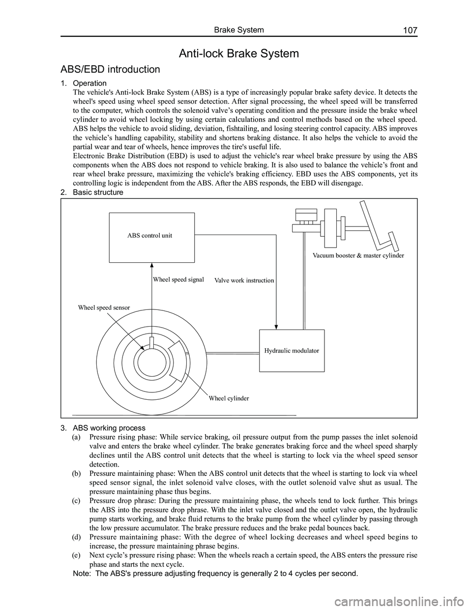
2. Basic structure
3. ABS working process
(a) Pressure rising phase: While service braking, oil pressure output from the pump passes the inlet solenoid
valve and enters the brake wheel cylinder. The brake generates braking force and the wheel speed sharply
declines until the ABS control unit detects that the wheel is starting to lock via the wheel speed sensor
detection.
(b) Pressure maintaining phase: When the ABS control unit detects that the wheel is starting to lock via wheel
speed sensor signal, the inlet solenoid valve closes, with the outlet solenoid valve shut as usual. The
pressure maintaining phase thus begins.
(c) Pressure drop phrase: During the pressure maintaining phase, the wheels tend to lock further. This brings
the ABS into the pressure drop phrase. With the inlet valve closed and the outlet valve open, the hydraulic
pump starts working, and brake fluid returns to the brake pump from the wheel cylinder by passing through
the low pressure accumulator. The brake pressure reduces and the brake pedal bounces back.
(d) Pressure maintaining phase: With the degree of wheel locking decreases and wheel speed begins to
increase, the pressure maintaining phrase begins.
(e) Next cycle’s pressure rising phase: When the wheels reach a certain speed, the ABS enters the pressure rise
phase and starts the next cycle.
Note: The ABS's pressure adjusting frequency is generally 2 to 4 cycles per second.
ABS control unit
Wheel speed sensor
Wheel speed signal
Wheel cylinder
Valve work instruction
Hydraulic modulator
Vacuum booster & master cylinder