rear GREAT WALL FLORID 2008 Service Manual
[x] Cancel search | Manufacturer: GREAT WALL, Model Year: 2008, Model line: FLORID, Model: GREAT WALL FLORID 2008Pages: 281, PDF Size: 43.97 MB
Page 2 of 281
Downloaded from www.Manualslib.com manuals search engine PREFACE
GWFLORID will build 1.3L (GW413EF, GW4G13) or 1.5L (GW4G15) gasoline engines, in which the
GW4G13 and GW4G15 engines will both incorporate the newest VVT technology which meets the Euro IV
emission standards. GWFLORID features McPherson technology on its chassis system. With an ultra light
body made from structural steel and high-intensity front and rear fender impact beams as well as a collision
impact absorption system, it is able to maintain the cab's integrity and safety to greater extent. We wrote this
maintenance manual in order to meet the demand of Great Wall after-sales service technicians. This manual
mainly introduces the areas of importance in regard to maintenance and care, and removal and installation of
each system's assembly and maintenance technical parameters.
To reduce the possibility of injury or property damage, read and follow t\
he instructions carefully:
This manual is provided by the Great Wall Motor Co., Ltd, and is written for the technician use. Any
maintenance or repair without proper prior training and tools or devices may result in personal injury of the
person performing the maintenance or others in the vicinity. It is also possible that damage to the vehicle will
occur or will lead to mechanical failure during normal operation.
Correct vehicle maintenance and repair is essential for the safety of the person performing regular
maintenance as well as the vehicle itself. If there is any component that needs to be replaced, use a
component with the same serial number or a serial number specified by the Great Wall Motor Co., Ltd. Never
use any part that has not been authorized by the Great Wall Motor Co., Ltd.
Any maintenance procedure introduced in this manual is effective for maintenance and repair. Some of
these procedures need specially designed tools.
Therefore, before using any vehicle part following any maintenance procedure or working with a tool
that has not been authorized by the Great Wall Motor Co., Ltd, check to make sure that none of the above
will endanger the safety of the person performing the work or the correc\
t operation of the vehicle.
This manual includes multiple "Warnings" and "Cautions," which should be strictly followed, so as to
reduce the possibility of injury during maintenance or repair. Improper maintenance or repair of the vehicle
may cause potential safety hazards. These "Warnings" and "Cautions" are not exhaustive. It is impossible for
the Great Wall Motor Co., Ltd, to warn against all the potential dangers caused by not properly following the
instructions.
Please read carefully the "Areas of Importance" before carrying out any maintenance or repair on the
airbag system's components or its surrounding electrical components. Action contrary to any of the "Areas of
Importance" may lead to the deployment of the airbag, resulting in injur\
y or unnecessary repair of the airbag.
To avoid accidental deployment of the airbag and its resulting injury, we suggest repairing the airbag
system before other vehicle systems if the airbag and the other vehicle \
systems both need repairing.
We have received generous support and help from many professional technicians during the preparation
of this manual. We would like to express our heartfelt gratitude to all of them.
Although we have tried our best to write this manual well, we do not guarantee that the entire content
in this manual is absolutely correct. Users may not make any legal claim against the Great Wall Motor Co.,
Ltd. in regards to this manual. Any loss caused by using this manual is not our responsibility. Because of
the writer's limited experience, there are likely mistakes in this manual, therefore we welcome any user
comments, suggestions, and corrections.
Great Wall Motor Co., Ltd. reserves the final right of explanation.
\
Editor
May 2008
Page 5 of 281

Downloaded from www.Manualslib.com manuals search engine Chapter Five: Transmission ........................................................................\
................................42
037A Transmission’s Overall External Schematics ....................................................43
Main Technical Parameters ..................................................................................\
....43
Transmission’s Proper Use and Care ........................................................................44
Technical Specifications for Transmission Installation and Adjustment .....................44
Areas of Importance ..................................................................................\
................45
Troubleshooting ..................................................................................\
.......................46
037A Transmission Structural Schematics ................................................................47
Clutch ...................................................................................\
......................................48
Gear Shift Fork and Fork Shaft ..................................................................................49
Transmission Case ..................................................................................\
..................50
Disassembling the Input Shaft Subassembly ............................................................56
Disassembling the Output Shaft Subassembly ..........................................................60
Disassembling the Shift Cover Subassembly ............................................................64
Disassembling the Differential Subassembly .............................................................68
Chapter Six: Suspension System ........................................................................\
.......................71
Suspension System Technical Parameters ...............................................................72
Front Suspension ...................................................................................\
....................73
Subframe and Front Stabilizer Bar ............................................................................77
Lower Swing Arm ...................................................................................\
....................80
Drive Shaft ..................................................................................\
...............................84
Rear Suspension ..................................................................................\
.....................86
Wheel and Tire ...................................................................................\
........................89
Chapter Seven: Brake System ........................................................................\
...........................94
Brake System Components Arrangement Schematics ..............................................95
Brake System Maintenance ...................................................................................\
....96
Brake Pedal ..................................................................................\
.............................98
Parking Brake Control Mechanism Assembly ..........................................................102
Vacuum Booster with Brake Cylinder Assembly ......................................................103
Anti-lock Brake System ...................................................................................\
.........107
ABS General Problem Maintenance and Areas of Importance ................................109
Steering Knuckle and Hub Brake Assembly ............................................................112
Front Brake Caliper ...................................................................................\
...............118
Rear Brake ...................................................................................\
............................124
Rear Support Axle ...................................................................................\
.................131
Chapter Eight: Steering System ........................................................................\
.......................134
Troubleshooting ..................................................................................\
.....................135
Steering System Maintenance .................................................................................137
Power Steering Fluid Instructions ............................................................................141
Page 7 of 281
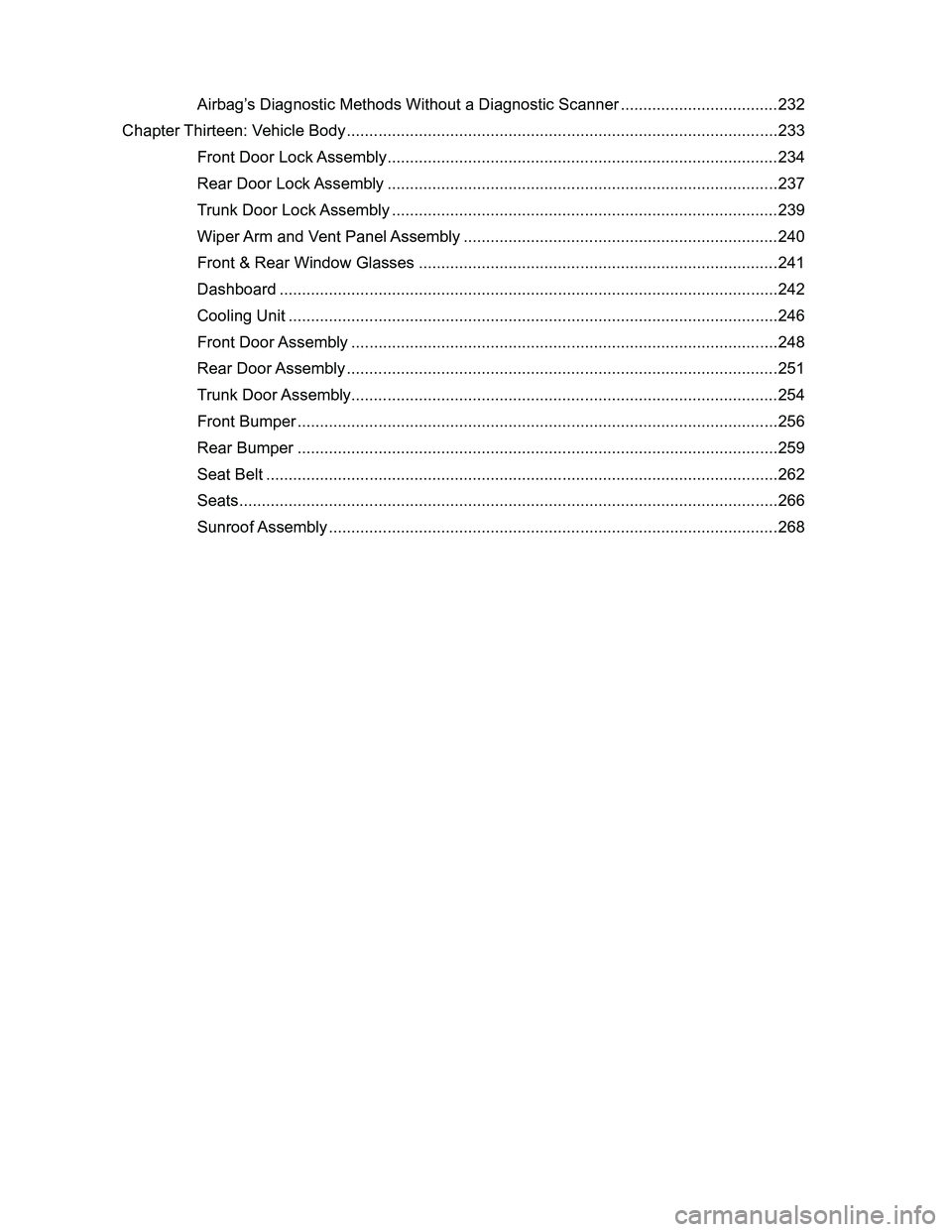
Downloaded from www.Manualslib.com manuals search engine Airbag’s Diagnostic Methods Without a Diagnostic Scanner ...................................232
Chapter Thirteen: Vehicle Body ........................................................................\
........................233
Front Door Lock Assembly ...................................................................................\
....234
Rear Door Lock Assembly ..................................................................................\
.....237
Trunk Door Lock Assembly ...................................................................................\
...239
Wiper Arm and Vent Panel Assembly ......................................................................240
Front & Rear Window Glasses ................................................................................241
Dashboard ..................................................................................\
.............................242
Cooling Unit ..................................................................................\
...........................246
Front Door Assembly ..................................................................................\
.............248
Rear Door Assembly ...................................................................................\
.............251
Trunk Door Assembly ...................................................................................\
............254
Front Bumper ...................................................................................\
........................256
Rear Bumper ..................................................................................\
.........................259
Seat Belt ..................................................................................\
................................262
Seats ...................................................................................\
.....................................266
Sunroof Assembly ...................................................................................\
.................268
Page 18 of 281
Downloaded from www.Manualslib.com manuals search engine 11Overall Parameters
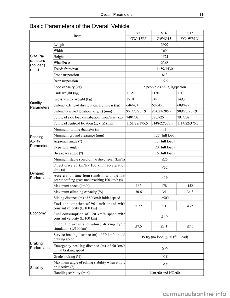
ItemS08 S16S12
GW413EFGW4G15YC4W75-31
Size Pa-
rameters
(no load)
(mm)
Length3907
Width1694
Height1521
Wheelbase2368
Tread: front/rear1459/1430
Front suspension813
Rear suspension726
Quality
Parameters
Load capacity (kg)5 people × (68±7) kg/person
Curb weight (kg)113511201118
Gross vehicle weight (kg)151014951493
Unload axle load distribution: front/rear (kg)646/434669/451689/429
Unload centroid location (x, y, z) (mm)951/27/285.9954/27/285.9909/27/285.9
Full load axle load distribution: front/rear (kg)748/707770/725791/702
Full load centroid location (x, y, z) (mm)1151/22/375.51148/22/375.51114/22/375.5
Passing
Ability
Parameters
Minimum turning diameter (m)11
Minimum ground clearance (mm)127 (full load)
Approach angle (°)17 (full load)
Departure angle (°)20 (full load)
Breakover angle (°)16 (full load)
Dynamic
Performance
Minimum stable speed of the direct gear (km/h)≤25
Direct drive 25 km/h - 100 km/h acceleration
time (s)≤32
Acceleration time from standstill with the first
gear to shifting gears until reaching 100 km/h (s)≤19
Maximum speed (km/h)162178152
Maximum climbing capacity (%)30.63434.3
Economy
Sliding distance (m) of 50 km/h initial speed≥500
F u e l c o n s u m p t i o n o f 9 0 k m / h s p e e d w i t h
constant velocity (L/100 km)5.796.14.25
Fuel consumption of 120 km/h speed with
constant velocity (L/100 km)≤8.5
U n d e r t h e u r b a n a n d s u b u r b d r i v i n g c y c l e
simulation (L/100 km)≤7.5≤8.1≤7.5
Braking
Performance
Service braking distance (m) of 50 km/h initial
braking speed19.0≤ (no load) ≤ 20 (full load)
Emergency braking distance (m) of 50 km/h
initial braking speed ≤38
Grade braking (%)≥18
Stability
Maximum angle of rolling stability when empty
or inactive (°)≥35
Handling stability (min)Nan≥60 and NZ≥60
Basic Parameters of the Overall Vehicle
Page 20 of 281
Downloaded from www.Manualslib.com manuals search engine 13Overall Parameters
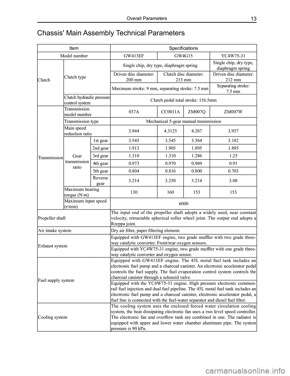
Chassis' Main Assembly Technical Parameters
ItemSpecifications
Model numberGW413EFGW4G15YC4W75-31
ClutchClutch type
Single chip, dry type, diaphragm springSingle chip, dry type,
diaphragm spring
Driven disc diameter:
200 mm
Clutch disc diameter:
213 mm
Driven disc diameter:
212 mm
Maximum stroke: 9 mm, separating stroke: 7.5 mmSeparating stroke:
7.5 mm
Clutch hydraulic pressure
control systemClutch pedal total stroke: 116.5mm
Transmission
Transmission
model number037ACC0011AZM007QZM007W
Transmission typeMechanical 5-gear manual transmission
Main speed
reduction ratio3.9444.31254.2673.937
Gear
transmission
ratio
1st gear3.5453.5453.3643.182
2nd gear1.9131.9051.8951.895
3rd gear1.3101.3101.2861.25
4th gear0.9730.9700.9690.91
5th gear0.8040.8160.8000.703
Reverse
gear3.2143.2503.2143.08
Maximum bearing
torque (N·m)130160153153
Maximum input speed
(r/min)6000
Propeller shaft
The input end of the propeller shaft adopts a widely used, near constant
velocity, retractable spherical roller wheel joint. The output end adopts a
Rzeppa joint.
Air intake systemDry air filter, paper filtering element.
Exhaust system
Equipped with GW413EF engine, two grade muffler with two grade three-
way catalytic converter. Front/rear oxygen sensors.
Equipped with YC4W75-31 engine, two grade muffler with one grade three-
way catalytic converter and oxygen sensor.
Fuel supply system
Equipped with GW413EF engine. The 45L metal fuel tank includes an
electronic fuel pump and a charcoal canister. An electronic accelerator pedal
controls the fuel supply. The fuel evaporation control system controls the
charcoal canister through a solenoid valve
Equipped with the YC4W75-31 engine. High pressure electronic common-
rail fuel injection and dual fuel pipeline. The 45L metal fuel tank includes an
electronic fuel pump and a charcoal canister, electronic accelerator pedal, a
fuel line is connected with the fuel-water separator and diesel fuel filter.
Cooling system
The cooling system uses the enclosed forced water circulation cooling
system, the heat dissipating electronic fan uses a two level speed controller.
The electronic fan and overflow tank are combined in one. The radiator is
equipped with upper and lower water chamber aluminum pipe. The system
pressure is 90 kPa.
Page 21 of 281
Downloaded from www.Manualslib.com manuals search engine GWFLORID Maintenance Manual14
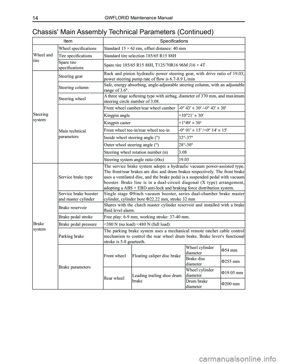
Chassis' Main Assembly Technical Parameters (Continued)
ItemSpecifications
Wheel and
tire
Wheel specificationsStandard 15 × 6J rim, offset distance: 40 mm
Tire specificationsStandard tire selection 185/65 R15 88H
Spare tire
specificationsSpare tire 185/65 R15 88H, T125/70R16 96M J16 × 4T
Steering
system
Steering gearRack and pinion hydraulic power steering gear, with drive ratio of 19.03,
power steering pump rate of flow is 6.7-8.9 L/min
Steering columnSafe, energy absorbing, angle-adjustable steering column, with an adjustable
range of 3.6°.
Steering wheelA three stage softening type with airbag, diameter of 370 mm, and maximum
steering circle number of 3.08.
Main technical
parameters
Front wheel camber/rear wheel camber-0° 43′ ± 30′ /-0° 43' ± 30'
Kingpin angle+10°21′ ± 30′
Kingpin caster+1°49′ ± 30′
Front wheel toe-in/rear wheel toe-in-0° 01′ ± 15′ /+0° 14' ± 15'
Inside wheel steering angle (°)32°-37°
Outer wheel steering angle (°)28°-30°
Steering wheel rotation number (n)3.08
Steering system angle ratio (i0ω)19.03
Brake
system
Service brake type
The service brake system adopts a hydraulic vacuum power-assisted type.
The front/rear brakes are disc and drum brakes respectively. The front brake
uses a ventilated disc, and the brake pedal is a suspended pedal with vacuum
booster. Brake line is in a dual-circuit diagonal (X type) arrangement,
adopting a ABS + EBD anti-lock and braking force distribution system.
Service brake booster
and master cylinder
Single stage Φ9inch vacuum booster, series dual-chamber brake master
cylinder, cylinder bore Φ22.22 mm, stroke 32 mm
Brake reservoirShares with the clutch master cylinder reservoir and installed with a brake
fluid level alarm.
Brake pedal strokeFree play: 6-9 mm, working stroke: 37-40 mm.
Brake pedal pressure<380 N (no load) <480 N (full load)
Parking brake
The parking brake system uses a mechanical remote ratchet cable control
mechanism to control the rear wheel drum brake. Brake lever's functional
stroke is 5-8 gearteeth.
Brake parameters
Front wheelFloating caliper disc brake
Wheel cylinder
diameterΦ54 mm
Brake disc
diameterΦ255 mm
Rear wheelLeading trailing shoe drum
brake
Wheel cylinder
diameterΦ19.05 mm
Drum brake
diameterΦ200 mm
Page 22 of 281
Downloaded from www.Manualslib.com manuals search engine 15Overall Parameters
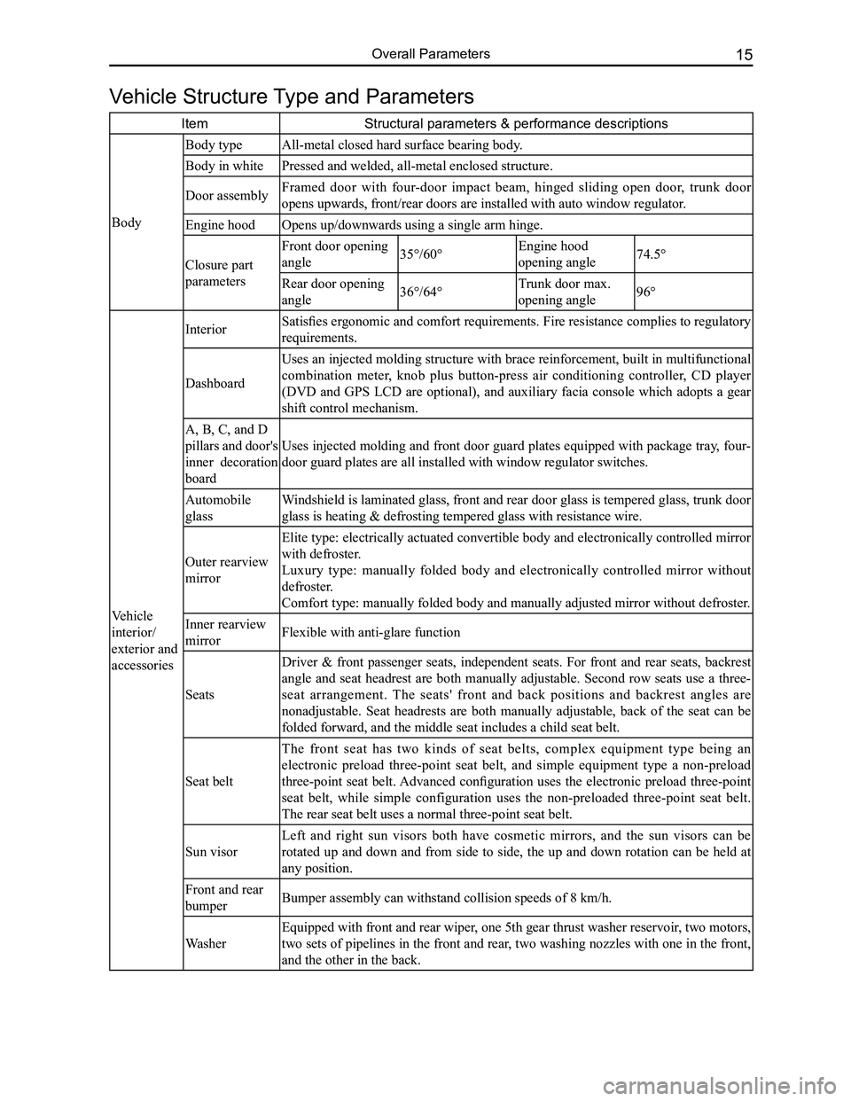
Vehicle Structure Type and Parameters
ItemStructural parameters & performance descriptions
Body
Body typeAll-metal closed hard surface bearing body.
Body in whitePressed and welded, all-metal enclosed structure.
Door assemblyFramed door with four-door impact beam, hinged sliding open door, trunk door
opens upwards, front/rear doors are installed with auto window regulator\
.
Engine hoodOpens up/downwards using a single arm hinge.
Closure part
parameters
Front door opening
angle35°/60°Engine hood
opening angle74.5°
Rear door opening
angle36°/64°Trunk door max.
opening angle96°
Vehicle
interior/
exterior and
accessories
Interior Satisfies ergonomic and comfort requirements. Fire resistance complies to regulatory
requirements.
Dashboard
Uses an injected molding structure with brace reinforcement, built in multifunctional
combination meter, knob plus button-press air conditioning controller, CD player
(DVD and GPS LCD are optional), and auxiliary facia console which adopts a gear
shift control mechanism.
A, B, C, and D
pillars and door's
inner decoration
board
Uses injected molding and front door guard plates equipped with package tray, four-
door guard plates are all installed with window regulator switches.
Automobile
glass
Windshield is laminated glass, front and rear door glass is tempered glass, trunk door
glass is heating & defrosting tempered glass with resistance wire.
Outer rearview
mirror
Elite type: electrically actuated convertible body and electronically controlled mirror
with defroster.
Luxury type: manually folded body and electronically controlled mirror without
defroster.
Comfort type: manually folded body and manually adjusted mirror without \
defroster.
Inner rearview
mirrorFlexible with anti-glare function
Seats
Driver & front passenger seats, independent seats. For front and rear seats, backrest
angle and seat headrest are both manually adjustable. Second row seats use a three-
seat arrangement. The seats' front and back positions and backrest angles are
nonadjustable. Seat headrests are both manually adjustable, back of the seat can be
folded forward, and the middle seat includes a child seat belt.
Seat belt
The front seat has two kinds of seat belts, complex equipment type being an
electronic preload three-point seat belt, and simple equipment type a non-preload
three-point seat belt. Advanced configuration uses the electronic preload three-point
seat belt, while simple configuration uses the non-preloaded three-point seat belt.
The rear seat belt uses a normal three-point seat belt.
Sun visor
Left and right sun visors both have cosmetic mirrors, and the sun visors can be
rotated up and down and from side to side, the up and down rotation can be held at
any position.
Front and rear
bumperBumper assembly can withstand collision speeds of 8 km/h.
Washer
Equipped with front and rear wiper, one 5th gear thrust washer reservoir, two motors,
two sets of pipelines in the front and rear, two washing nozzles with one in the front,
and the other in the back.
Page 23 of 281
Downloaded from www.Manualslib.com manuals search engine GWFLORID Maintenance Manual16
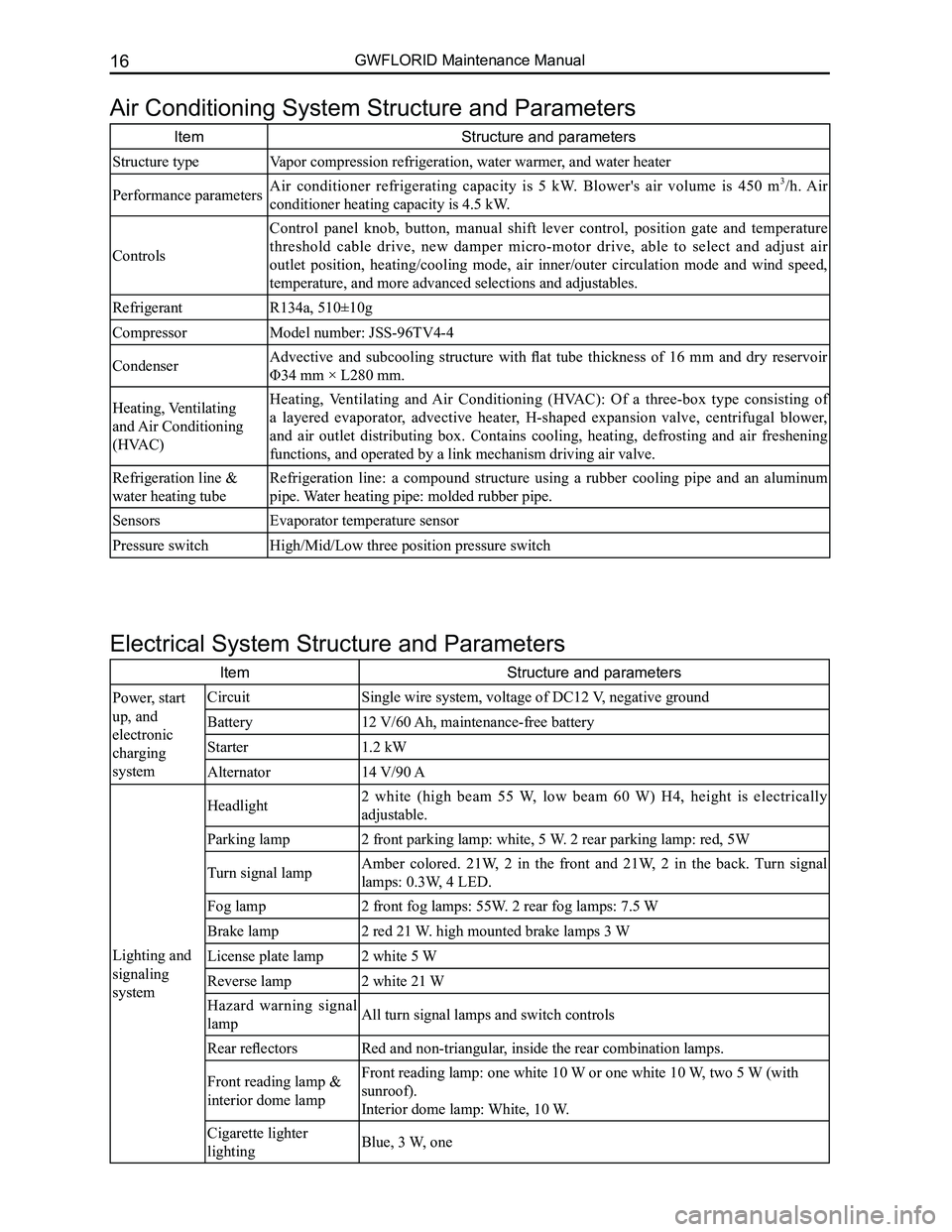
Air Conditioning System Structure and Parameters
ItemStructure and parameters
Structure typeVapor compression refrigeration, water warmer, and water heater
Performance parametersAir conditioner refrigerating capacity is 5 kW. Blower's air volume is 450 m3/h. Air
conditioner heating capacity is 4.5 kW.
Controls
Control panel knob, button, manual shift lever control, position gate and temperature
threshold cable drive, new damper micro-motor drive, able to select and adjust air
outlet position, heating/cooling mode, air inner/outer circulation mode and wind speed,
temperature, and more advanced selections and adjustables.
RefrigerantR134a, 510±10g
CompressorModel number: JSS-96TV4-4
CondenserAdvective and subcooling structure with flat tube thickness of 16 mm and dry reservoir
Φ34 mm × L280 mm.
Heating, Ventilating
and Air Conditioning
(HVAC)
Heating, Ventilating and Air Conditioning (HVAC): Of a three-box type consisting of
a layered evaporator, advective heater, H-shaped expansion valve, centrifugal blower,
and air outlet distributing box. Contains cooling, heating, defrosting and air freshening
functions, and operated by a link mechanism driving air valve.
Refrigeration line &
water heating tube
Refrigeration line: a compound structure using a rubber cooling pipe and an aluminum
pipe. Water heating pipe: molded rubber pipe.
SensorsEvaporator temperature sensor
Pressure switchHigh/Mid/Low three position pressure switch
Electrical System Structure and Parameters
ItemStructure and parameters
Power, start
up, and
electronic
charging
system
CircuitSingle wire system, voltage of DC12 V, negative ground
Battery12 V/60 Ah, maintenance-free battery
Starter1.2 kW
Alternator14 V/90 A
Lighting and
signaling
system
Headlight2 white (high beam 55 W, low beam 60 W) H4, height is electrically
adjustable.
Parking lamp2 front parking lamp: white, 5 W. 2 rear parking lamp: red, 5W
Turn signal lampAmber colored. 21W, 2 in the front and 21W, 2 in the back. Turn signal
lamps: 0.3W, 4 LED.
Fog lamp2 front fog lamps: 55W. 2 rear fog lamps: 7.5 W
Brake lamp2 red 21 W. high mounted brake lamps 3 W
License plate lamp2 white 5 W
Reverse lamp2 white 21 W
Hazard warning signal
lampAll turn signal lamps and switch controls
Rear reflectorsRed and non-triangular, inside the rear combination lamps.
Front reading lamp &
interior dome lamp
Front reading lamp: one white 10 W or one white 10 W, two 5 W (with
sunroof).
Interior dome lamp: White, 10 W.
Cigarette lighter
lightingBlue, 3 W, one
Page 24 of 281
Downloaded from www.Manualslib.com manuals search engine 17Overall Parameters
ItemStructure and parameters
Dashboard
system
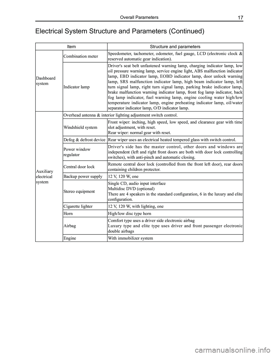
Combination meter Speedometer, tachometer, odometer, fuel gauge, LCD (electronic clock &
reserved automatic gear indication).
Indicator lamp
Driver's seat belt unfastened warning lamp, charging indicator lamp, low
oil pressure warning lamp, service engine light, ABS malfunction indicator
lamp, EBD indicator lamp, EOBD indicator lamp, door unlock warning
lamp, SRS malfunction indicator lamp, high beam indicator lamp, left
turn signal lamp, right turn signal lamp, parking brake indicator lamp,
brake malfunction warning indicator lamp, front fog lamp indicator, back
fog lamp indicator, fuel warning lamp, engine cooling water high/low
temperature indicator lamp, engine preheating indicator lamp, oil/water
separator indicator lamp, O/D indicator lamp.
Auxiliary
electrical
system
Overhead antenna & interior lighting adjustment switch control.
Windshield system
Front wiper: inching, high speed, low speed, and clearance gear with time
slot adjustment, with reset.
Rear wiper: normal gear with reset.
Defog & defrost deviceRear wiper uses an electrical heated tempered glass with switch control.\
Power window
regulator
D r i v e r ' s s i d e h a s t h e m a s t e r c o n t r o l , o t h e r d o o r s a n d w i n d o w s a r e
independent (left and right front doors are both with door lock controlling
switches), with anti-pinch and automatic closing.
Central door lockRemote central door lock (controlled from the front left door), rear doors
containing children protector.
Backup power supply12 V, 120 W, one
Stereo equipment
Single CD, audio input interface
Multidisc DVD (optional)
There are 4 speakers in the standard configuration, 6 in the luxury and elite
configuration.
Cigarette lighter12 V, 120 W, with lighting, one
HornHigh/low disc type horn
Airbag
Comfort type uses a driver side electronic airbag
Luxury type and elite type uses driver and front passenger electronic
double airbags
EngineWith immobilizer system
Electrical System Structure and Parameters (Continued)
Page 26 of 281
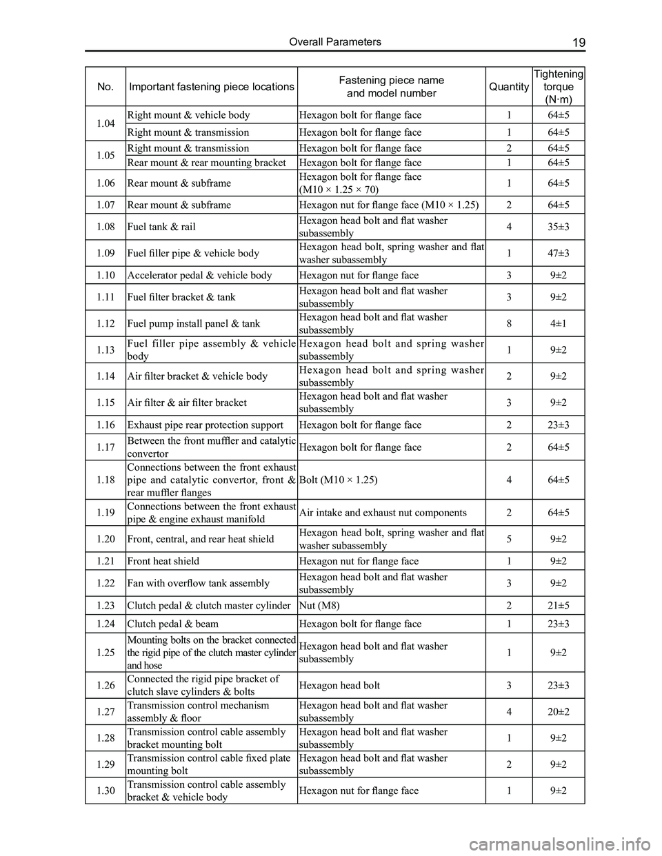
Downloaded from www.Manualslib.com manuals search engine 19Overall Parameters
No.Important fastening piece locationsFastening piece name
and model numberQuantity
Tightening
torque
(N·m)
1.04Right mount & vehicle bodyHexagon bolt for flange face164±5
Right mount & transmissionHexagon bolt for flange face 164±5
1.05Right mount & transmissionHexagon bolt for flange face 264±5
Rear mount & rear mounting bracketHexagon bolt for flange face 164±5
1.06Rear mount & subframeHexagon bolt for flange face
(M10 × 1.25 × 70)164±5
1.07Rear mount & subframeHexagon nut for flange face (M10 × 1.25)264±5
1.08Fuel tank & railHexagon head bolt and flat washer
subassembly435±3
1.09Fuel filler pipe & vehicle bodyHexagon head bolt, spring washer and flat
washer subassembly147±3
1.10Accelerator pedal & vehicle bodyHexagon nut for flange face39±2
1.11Fuel filter bracket & tankHexagon head bolt and flat washer
subassembly39±2
1.12Fuel pump install panel & tankHexagon head bolt and flat washer
subassembly84±1
1.13Fuel filler pipe assembly & vehicle
body
H e x a g o n h e a d b o l t a n d s p r i n g w a s h e r
subassembly19±2
1.14Air filter bracket & vehicle bodyH e x a g o n h e a d b o l t a n d s p r i n g w a s h e r
subassembly29±2
1.15Air filter & air filter bracketHexagon head bolt and flat washer
subassembly39±2
1.16Exhaust pipe rear protection supportHexagon bolt for flange face223±3
1.17Between the front muffler and catalytic
convertorHexagon bolt for flange face264±5
1.18
Connections between the front exhaust
pipe and catalytic convertor, front &
rear muffler flanges
Bolt (M10 × 1.25)464±5
1.19Connections between the front exhaust
pipe & engine exhaust manifoldAir intake and exhaust nut components264±5
1.20Front, central, and rear heat shieldHexagon head bolt, spring washer and flat
washer subassembly59±2
1.21Front heat shieldHexagon nut for flange face19±2
1.22Fan with overflow tank assemblyHexagon head bolt and flat washer
subassembly39±2
1.23Clutch pedal & clutch master cylinderNut (M8)221±5
1.24Clutch pedal & beamHexagon bolt for flange face123±3
1.25
Mounting bolts on the bracket connected
the rigid pipe of the clutch master cylinder
and hose
Hexagon head bolt and flat washer
subassembly19±2
1.26Connected the rigid pipe bracket of
clutch slave cylinders & boltsHexagon head bolt323±3
1.27Transmission control mechanism
assembly & floor
Hexagon head bolt and flat washer
subassembly420±2
1.28Transmission control cable assembly
bracket mounting bolt
Hexagon head bolt and flat washer
subassembly19±2
1.29Transmission control cable fixed plate
mounting bolt
Hexagon head bolt and flat washer
subassembly29±2
1.30Transmission control cable assembly
bracket & vehicle bodyHexagon nut for flange face19±2