service reset GREAT WALL FLORID 2008 Service Manual
[x] Cancel search | Manufacturer: GREAT WALL, Model Year: 2008, Model line: FLORID, Model: GREAT WALL FLORID 2008Pages: 281, PDF Size: 43.97 MB
Page 24 of 281

Downloaded from www.Manualslib.com manuals search engine 17Overall Parameters
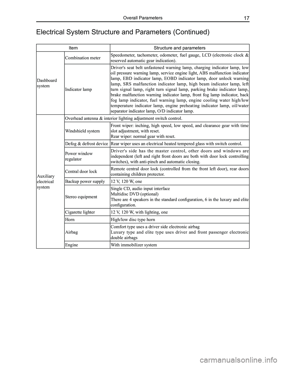
ItemStructure and parameters
Dashboard
system
Combination meter Speedometer, tachometer, odometer, fuel gauge, LCD (electronic clock &
reserved automatic gear indication).
Indicator lamp
Driver's seat belt unfastened warning lamp, charging indicator lamp, low
oil pressure warning lamp, service engine light, ABS malfunction indicator
lamp, EBD indicator lamp, EOBD indicator lamp, door unlock warning
lamp, SRS malfunction indicator lamp, high beam indicator lamp, left
turn signal lamp, right turn signal lamp, parking brake indicator lamp,
brake malfunction warning indicator lamp, front fog lamp indicator, back
fog lamp indicator, fuel warning lamp, engine cooling water high/low
temperature indicator lamp, engine preheating indicator lamp, oil/water
separator indicator lamp, O/D indicator lamp.
Auxiliary
electrical
system
Overhead antenna & interior lighting adjustment switch control.
Windshield system
Front wiper: inching, high speed, low speed, and clearance gear with time
slot adjustment, with reset.
Rear wiper: normal gear with reset.
Defog & defrost deviceRear wiper uses an electrical heated tempered glass with switch control.\
Power window
regulator
D r i v e r ' s s i d e h a s t h e m a s t e r c o n t r o l , o t h e r d o o r s a n d w i n d o w s a r e
independent (left and right front doors are both with door lock controlling
switches), with anti-pinch and automatic closing.
Central door lockRemote central door lock (controlled from the front left door), rear doors
containing children protector.
Backup power supply12 V, 120 W, one
Stereo equipment
Single CD, audio input interface
Multidisc DVD (optional)
There are 4 speakers in the standard configuration, 6 in the luxury and elite
configuration.
Cigarette lighter12 V, 120 W, with lighting, one
HornHigh/low disc type horn
Airbag
Comfort type uses a driver side electronic airbag
Luxury type and elite type uses driver and front passenger electronic
double airbags
EngineWith immobilizer system
Electrical System Structure and Parameters (Continued)
Page 225 of 281

Downloaded from www.Manualslib.com manuals search engine GWFLORID Maintenance Manual218
detection but also during the diagnostic detection cycle. However, if a short circuit on the power supply causes
a malfunction, and the low-end transistor is opened while malfunctioned, the low-end transistor can only be
detected when starting up detection, as to avoid faulty execution.
(b) Ignition voltage is provided by a pressure increase converter.
(c) Acceleration sensor performs self-detection when starting up detection.
(d) Allowed offset range of the acceleration sensor during a diagnostic cycle.
(e) Microcontroller includes AD converter, ROM, RAM, etc.
(f) Security sensor status.
Caution: There is a short-circuiting bar inside the squib circuit connector. When the connector is not
connected, the short circuit happens between the squib circuit's terminal (+) and terminal (-), as to
avoid faulty deployment caused by static electricity. When the connector is bad and the short-circuiting
bar is connected, the fault symptom may not be eliminated.
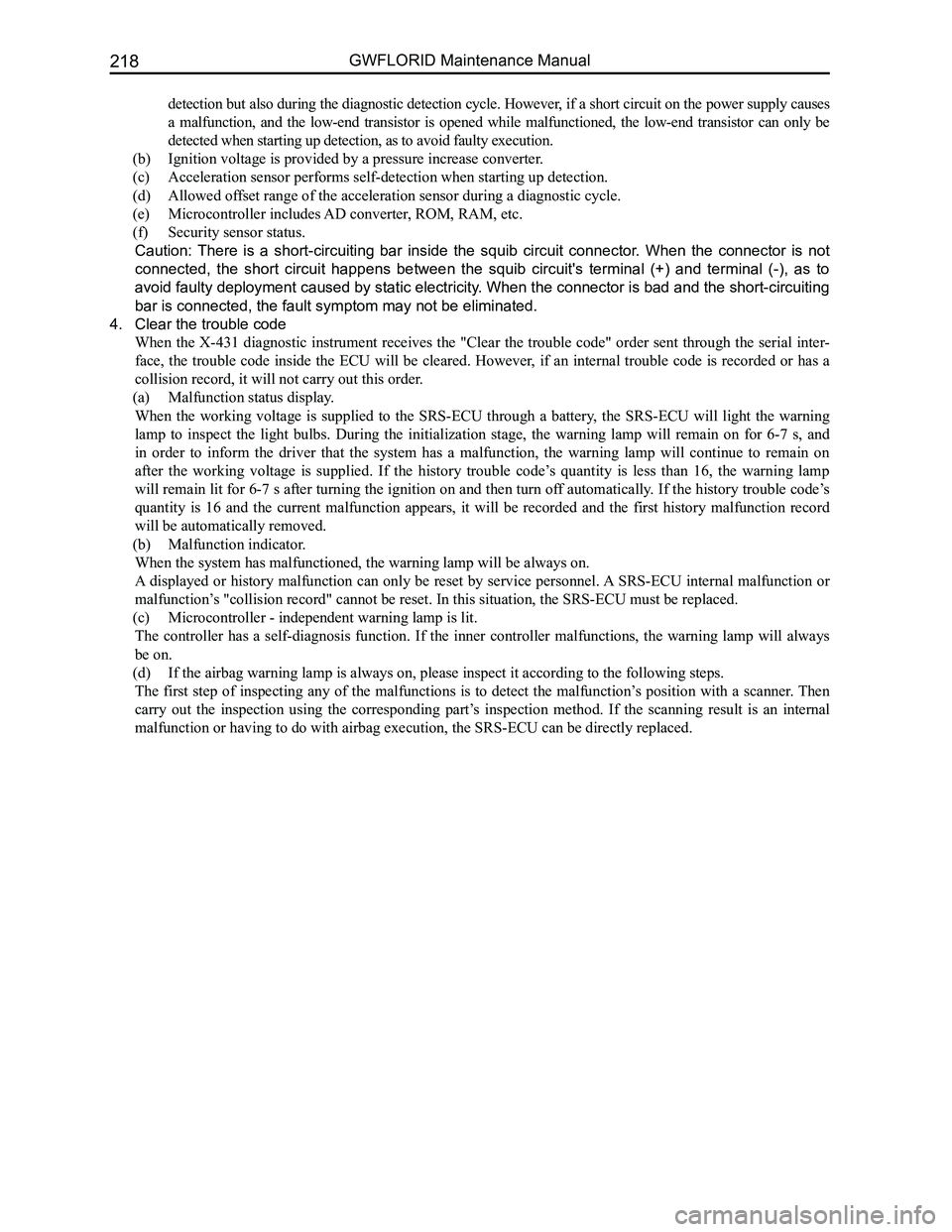
4. Clear the trouble code
When the X-431 diagnostic instrument receives the "Clear the trouble code" order sent through the serial inter-
face, the trouble code inside the ECU will be cleared. However, if an internal trouble code is recorded or has a
collision record, it will not carry out this order.
(a) Malfunction status display.
When the working voltage is supplied to the SRS-ECU through a battery, the SRS-ECU will light the warning
lamp to inspect the light bulbs. During the initialization stage, the warning lamp will remain on for 6-7 s, and
in order to inform the driver that the system has a malfunction, the warning lamp will continue to remain on
after the working voltage is supplied. If the history trouble code’s quantity is less than 16, the warning lamp
will remain lit for 6-7 s after turning the ignition on and then turn off automatically. If the history trouble code’s
quantity is 16 and the current malfunction appears, it will be recorded and the first history malfunction record
will be automatically removed.
(b) Malfunction indicator.
When the system has malfunctioned, the warning lamp will be always on.
A displayed or history malfunction can only be reset by service personnel. A SRS-ECU internal malfunction or
malfunction’s "collision record" cannot be reset. In this situation, the SRS-ECU mus\
t be replaced.
(c) Microcontroller - independent warning lamp is lit.
The controller has a self-diagnosis function. If the inner controller malfunctions, the warning lamp will always
be on.
(d) If the airbag warning lamp is always on, please inspect it according to the following steps.
The first step of inspecting any of the malfunctions is to detect the malfunction’s position with a scanner. Then
carry out the inspection using the corresponding part’s inspection method. If the scanning result is an internal
malfunction or having to do with airbag execution, the SRS-ECU can be di\
rectly replaced.