charging GREAT WALL HOVER 2006 Service Repair Manual
[x] Cancel search | Manufacturer: GREAT WALL, Model Year: 2006, Model line: HOVER, Model: GREAT WALL HOVER 2006Pages: 425, PDF Size: 26.05 MB
Page 19 of 425

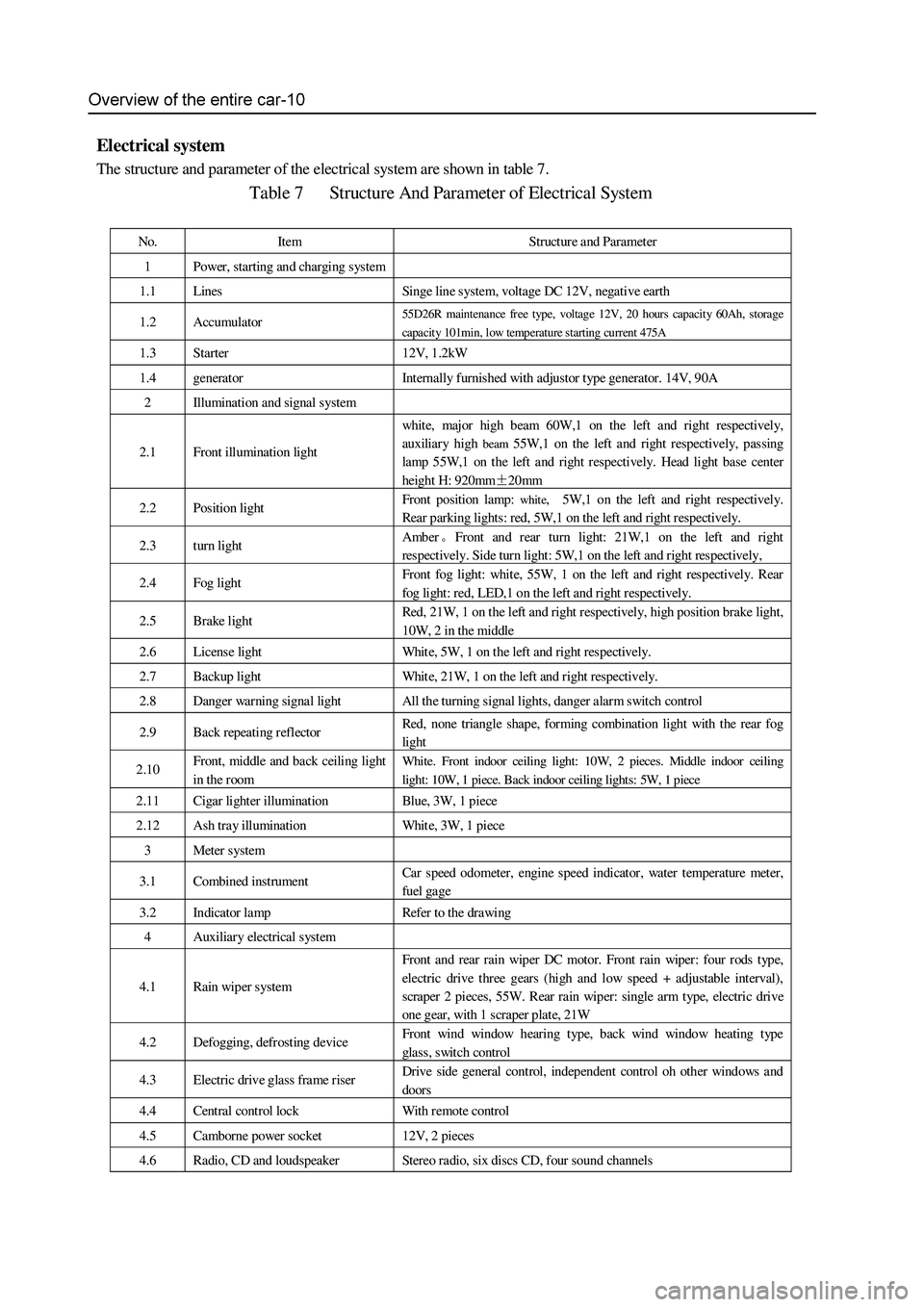
Electrical system
The structure and parameter of the electrical system are shown in table 7.
Table 7 Structure And Parameter of Electrical System
No. Item Structure and Parameter
1 Power, starting and charging system
1.1 Lines Singe line system, voltage DC 12V, negative earth
1.2 Accumulator 55D26R maintenance free type, voltage 12V, 20 hours capacity 60Ah, storage
capacity 101min, low temperature starting current 475A
1.3 Starter 12V, 1.2kW
1.4 generator Internally furnished with adjustor type generator. 14V, 90A
2 Illumination and signal s ystem
2.1 Front illumination light
white, major high beam 60W,1 on the left and right respectively,
auxiliary high
beam 55W,1 on the left and right respectively, passing
lamp 55W,1 on the left and right respectively. Head light base center
height H: 920mm±20mm
2.2 Position light Front position lamp: white, 5W,1 on the left and right respectively.
Rear parking lights: red, 5W,1 on the left and right respectively.
2.3 turn light Amber。Front and rear turn light: 21W,1 on the left and right
respectively. Side turn light: 5W,1 on the left and right respectively,
2.4 Fog light Front fog light: white, 55W, 1 on the left and right respectively. Rear
fog light: red, LED,1 on the left and right respectively.
2.5 Brake light Red, 21W, 1 on the left and right respectively, high position brake light,
10W, 2 in the middle
2.6 License light White, 5W, 1 on the left and right respectively.
2.7 Backup light White, 21W, 1 on the left and right respectively.
2.8 Danger warning signal light All the turning signal lights, danger alarm switch control
2.9 Back repeating reflector Red, none triangle shape, forming combination light with the rear fog
light
2.10 Front, middle and back ceiling light
in the room White. Front indoor ceiling light: 10W, 2 pieces. Middle indoor ceiling
light: 10W, 1 piece. Back indoor ceiling lights: 5W, 1 piece
2.11 Cigar lighter illumination Blue, 3W, 1 piece
2.12 Ash tray illumination White, 3W, 1 piece
3 Meter system
3.1 Combined instrument Car speed odometer, engine speed indicator , water t emperature met er,
fuel gage
3.2 Indicator lamp Refer to the drawing
4 Auxiliary electrical system
4.1 Rain wiper system Front and rear rain wiper DC motor. Front rain wiper: four rods type,
electric drive three gears (high and low speed + adjustable interval),
scraper 2 pieces, 55W. Rear rain wiper: single arm type, electric drive
one gear, with 1 scraper plate, 21W
4.2 Defogging, defrosting device Front wind window hearing type, back wind window heating type
glass, switch control
4.3 Electric drive glass frame riser Drive side general control, independent control oh other windows and
doors
4.4 Central control lock With r emote control
4.5 Camborne power socket 12V, 2 pieces
4.6 Radio, CD and loudspeaker Stereo radio, six discs CD, four sound channels
Page 367 of 425

CD Player and Air Conditioning System-14
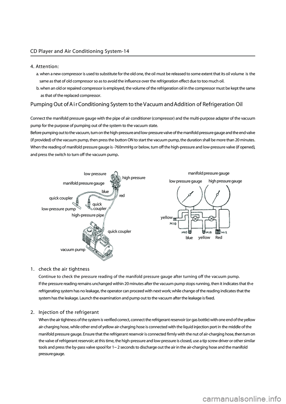
Pumping Out of A i r Conditioning System to the Vacuum and Addition of Refrigeration Oil
Connect the manifold pressure gauge with the pipe of air conditioner (compressor) and the multi-purpose adapter of the vacuum
pump for the purpose of pumping out of the system to the vacuum state.
Before pumping out to the vacuum, turn on the high-pressure and low-pressure valve of the
manifold pressure gauge and the end valve
(if provided) of the vacuum pump, then press the button ON to start the vacuum pump, the duration shall be more than 20 minutes
.
When the reading of manifold pressure gauge is -760mmHg or below, turn off the high-pressure and low-pressure valve (if opened)
,
and press the switch to turn off the vacuum pum
p.
1 . check the air tightness
Continue to check the pressure reading of the manifold pressure gauge after turning off the vacuum pump.
If the pressure reading remains unchanged within 20 minutes after the vacuum pump stops running, then it indicates that th
e
refrigerating system has no leakage, the operator can proceed with next work; while change of the reading indicates that the
system has the leakage. Launch the examination and pump out to the vacuum after the leakage is fixed.
2 . Injection of the refrigerant
When the air tightness of the system is verified correct, connect the refrigerant reservoir (or gas bottle) with one end of the yellow
a ir-charging hose, while other end of yellow air-charging hose is connected with the liquid injection port in the middle of the
manifold pressure gauge. Ensure that the refrigerant reservoir is connected firmly with the nut of air-charging hose, then turn on
the valve of refrigerant reservoir; at this time, the high-pressure and low-pressure is closed, use a tip screw driver or other
similar
tools and press the by-pass valve spool for 1~ 2 seconds to discharge out the air in the air-charging hose and the manifold
pressure gauge.
low p ressure
high pressure
manifold pressure gauge
quick coupler
l ow-pressure pump
high-pressure pipe
quick coupler
quick
coupler
red
blue
vacuum pum
p
manifold pressure gauge
low pressure gauge high
pressure gauge
Red
blue
yellow
yellow
4. Attention:
a. when a new compressor is used to substitute for the old one, the oil must be released to some extent that its oil volume is the
same as that of old compressor so as to avoid the influence over the refrigeration effect due to too much oil.
b. when an old or repaired compressor is employed, the volume of the refrigeration oil in the compressor must be kept the sam
e
as that of the replaced
compressor.
Page 382 of 425

Safety airbag-12
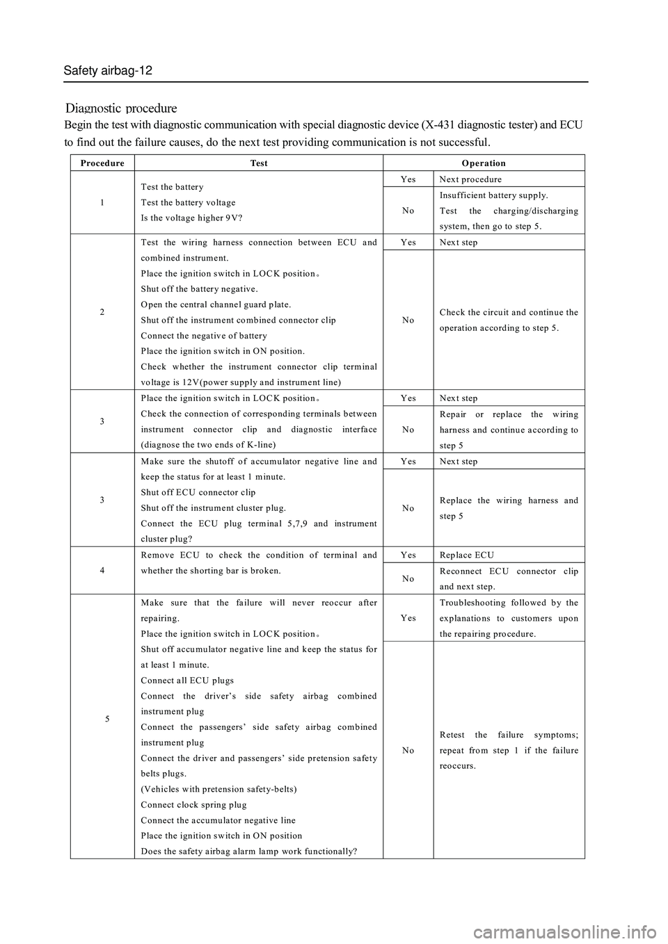
Begin the test with diagnostic communication with special diagnostic device (X-431 diagnostic tester) and ECU
to find out the failure causes, do the next test providing communication is not successful.
Procedure Te s t Operation
Yes Next procedure
1 Test the battery
Test the battery voltage
Is the voltage higher 9V? No Insufficient battery supply.
Test the charging/discharging
system, then go to step 5.
Yes Next step
2 Test the wiring harness connection between ECU and
combined instrument.
Place the ignition switch in LO C K position。
Shut off the battery negative.
O pen the central channel guard plate.
Shut off the instrument combined connector clip
Connect the negative of battery
Place the ignition switch in ON position.
Check whether the instrument connector clip terminal
voltage is 12V(power supply and instrument line) No Check the circuit and continue the
operation according to step 5.
Yes Next step
3 Place the ignition switch in LO C K position。
Check the connection of corresponding terminals between
instrument connector clip and diagnostic interface
(diagnose the two ends of K-line) No Repair or replace the wiring
harness and continue according to
step 5
Yes Next step
3 Make sure the shutoff of accumulator negative line and
keep the status for at least 1 minute.
Shut off ECU connector clip
Shut off the instrument cluster plug.
Connect the ECU plug terminal 5,7,9 and instrument
cluster plug? No Replace the wiring harness and
step 5
Yes Replace ECU
4 Remove EC U to check the condition of term inal and
whether the shorting bar is broken.
No Reconnect EC U connector clip
and next step.
Yes Troubleshooting followed by the
explanations to customers upon
the repair ing pro ced ur e.
5
Make sure that the failure will never reoccur after
repairing.
Place the ignition switch in LO C K position。
Shut off accumulator negative line and keep the status for
at least 1 m in ute.
Connect all ECU plugs
Connect the driver’s side safety airbag combined
instrum ent p lug
Connect the passengers’ side safety airbag combined
instrum ent p lug
Connect the driver and passengers’ side pretension safety
belts plugs.
(Vehicles with pretension safety-b elts)
Connect clock spring plug
Connect the accumulator negative line
Place the ignition switch in ON position
Does the safety airbag alarm lamp work functionally? No Retest the failure symptoms;
repeat from step 1 if the failure
reoccurs.
Page 384 of 425

Safety airbag-14
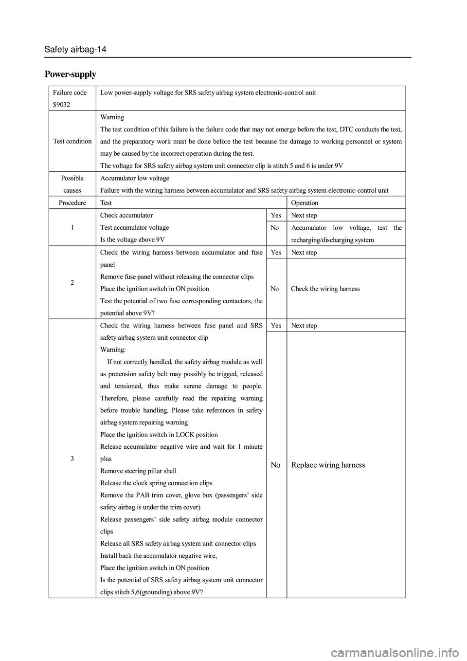
Power-supply
Failure code
$9032 Low power-supply voltage for SRS safety airbag system electronic-control unit
Test condition Warning
The test condition of this failure is the failure code that may not emerge before the test, DTC conducts the test,
and the preparatory work must be done before the test because the damage to working personnel or system
may be caused by the incorrect op eration during the test.
The voltage for SRS safety airbag system unit connector clip is stitch 5 and 6 is under 9V
Possible
caus es Accumulator low voltage
Failure with the wiring harness between accumulator and SRS safety airbag system electronic-control unit
Procedure Test Operation
Yes Next step
1 Check accumulator
Test accumulator voltage
Is the voltage above 9V No Accumulator low voltage, test the
recharging/discharging system
Yes Next step
2 Check the wiring harness between accumulator and fuse
panel
Remove fuse panel without releasing the connector clips
Place the ignition switch in ON position
Test the potential of two fuse corresponding contactors, the
potential above 9V? No Check the wiring harness
Yes Next step
3 Check the wiring harness between fuse panel and SRS
safety airbag system unit connector clip
Warning:
If not correctly handled, the safety airbag module as well
as pretension safety belt may possibly be trigged, released
and tensioned, thus make serene damage to people.
Ther efor e, pleas e carefully r ead the r epairing warning
before trouble handling. Please take references in safety
airbag system repairing warning
Place the ignition switch in LOCK position
Release accumulator negative wire and wait for 1 minute
plus
Remove steering pillar shell
Release the clock spring connection clips
Remove the PAB trim cover, glove box (passengers’ side
safety airbag is under the trim cover)
Release passengers’ side safety airbag module connector
clips
Release all SRS safety airbag system unit connector clips
Install back the accumulator negative wire,
Place the ignition switch in ON position
Is the potential of SRS safety airbag system unit connector
clips stitch 5,6(grounding) above 9V? No Replace wiring harness