wheel bolt torque GREAT WALL HOVER 2006 Service Repair Manual
[x] Cancel search | Manufacturer: GREAT WALL, Model Year: 2006, Model line: HOVER, Model: GREAT WALL HOVER 2006Pages: 425, PDF Size: 26.05 MB
Page 16 of 425
Overview of the entire car-7
Suspension
The front suspension is the torsion bar spring, double-cylinder inflatable hydraulic damper, transverse stabilizer rod, double
cross-arm independent suspension. The distance between the center of front shaft of lower arm fixing nut and level ground is
295mm±1mm.
The rear suspension is the four-connecting rod, coil spring, double-cylinder inflatable hydraulic damper, transverse stabilizer
rod, no indep endent suspension.
Carriage
Peripheral trapezoidal structure; welded by two box section longitudinal beams and several box or tube section cross beams.
Steering system
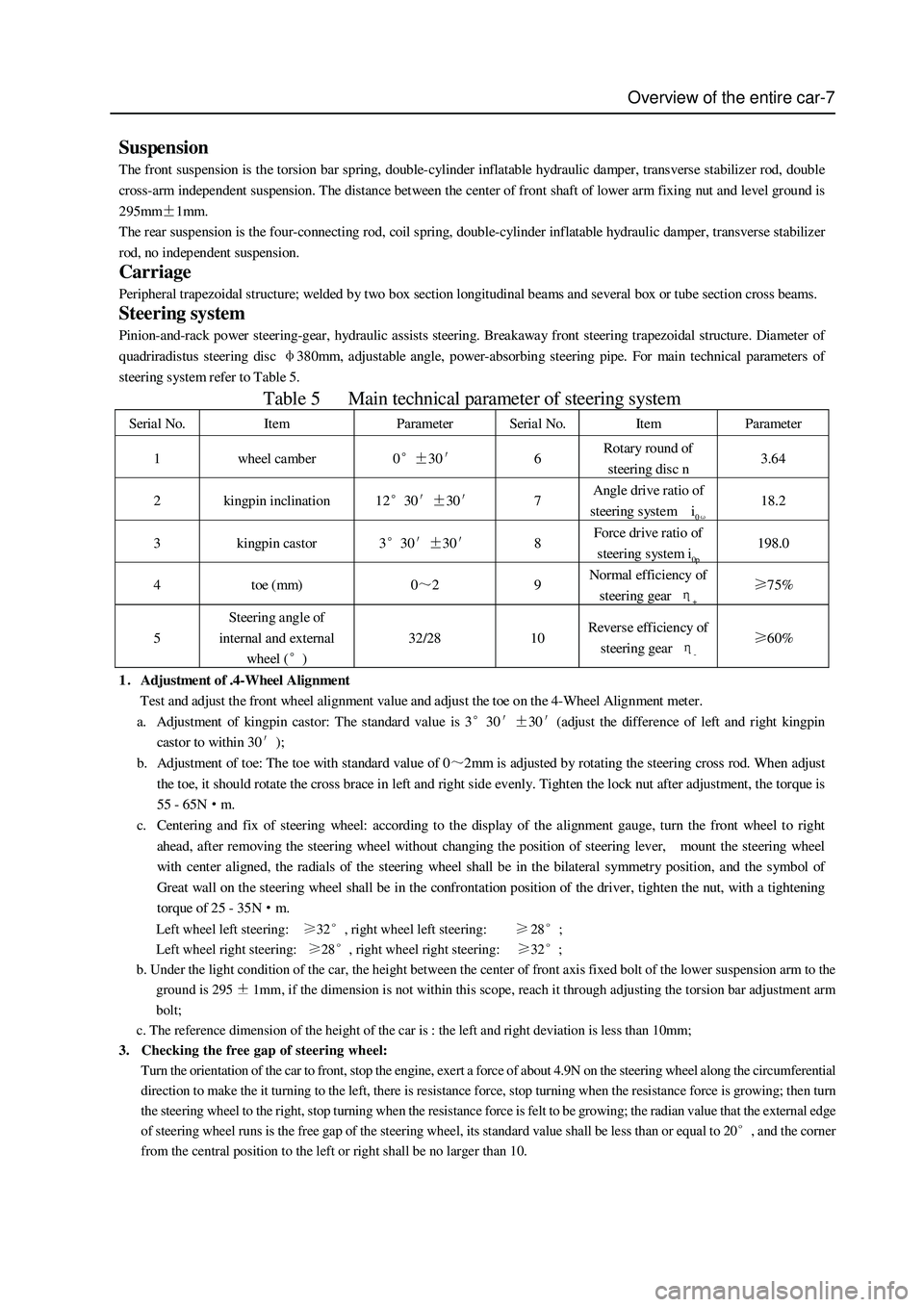
Pinion-and-rack power steering-gear, hydraulic assists steering. Breakaway front steering trapezoidal structure. Diameter of
quadriradistus steering disc φ380mm, adjustable angle, power-absorbing steering pipe. For main technical parameters of
steering s ystem refer to Table 5.
Table 5 Main technical parameter of steering system
Serial No. Item Parameter Serial No. Item Parameter
1 wheel camber 0°±30′ 6 Rotary round of
steering disc n 3.64
2 kingpin inclination 12°30′±30′ 7 Angle drive ratio of
steering system i0ω 18.2
3 kingpin castor 3°30′±30′ 8 Force drive ratio of
steering s ystem i0p 198.0
4 toe (mm) 0~2 9 Normal efficiency of
steering gear η+ ≥75%
5 Steering angle of
internal and external
wheel (°) 32/28 10 Revers e efficiency of
steering gear η- ≥60%
1.Adjustment of .4-Wheel Alignment
Test and adjust the front wheel alignment value and adjust the toe on the 4-Wheel Alignment meter.
a. Adjustment of kingpin castor: The standard value is 3°30′±30′(adjust the difference of left and right kingpin
castor to within 30′);
b. Adjustment of toe: The toe with standard value of 0~2mm is adjusted by rotating the steering cross rod. When adjust
the toe, it should rotate the cross brace in left and right side evenly. Tighten the lock nut after adjustment, the torque is
55 - 65N·m.
c. Centering and fix of steering wheel: according to the display of the alignment gauge, turn the front wheel to right
ahead, after removing the steering wheel without changing the position of steering lever, mount the steering wheel
with center aligned, the radials of the steering wheel shall be in the bilateral symmetry position, and the symbol of
Great wall on the steering wheel shall be in the confrontation position of the driver, tighten the nut, with a tightening
torque of 25 - 35N·m.
Left wheel left steering: 32, right wheel left steering:28;
Left wheel right steering:
28, right wheel right steering: 32;
b. Under the light condition of the car, the height between the center of front axis fixed bolt of the lower suspension arm to the
ground is 295
1mm, if the dimension is not within this scope, reach it through adjusting the torsion bar adjustment arm
bolt;
c. The reference dimension of the height of the car is : the left and right deviation is less than 10mm;
3. Checking the free gap of steering wheel:
Turn the orientation of the car to front, stop the engine, exert a force of about 4.9N on the steering wheel along the circumferential
direction to make the it turning to the left, there is resistance force, stop turning when the resistance force is growing; then turn
the steering wheel to the right, stop turning when the resistance force is felt to be growing; the radian value that the external edge
of steering wheel runs is the free gap of the steering wheel, its standard value shall be less than or equal to 20
, and the corner
from the central position to the left or right shall be no larger than 10.
Page 36 of 425
Clutch-6
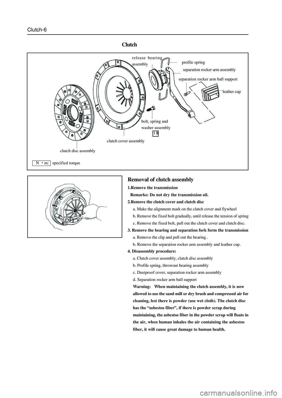
Clutch
4. Disassembly procedure:
a. Clutch cover assembly, clutch disc assembly
b. Profile spring, throwout bearing assembly
c. Dustproof cover, separation rocker arm assembly
d. Separation rocker arm ball support
Warning: When maintaining the clutch assembly, it is now
allowed to use the sand mill or dry brush and compressed air for
cleaning, lest there is powder (use wet cloth). The clutch disc
has the “asbestos fiber”, if there is powder scrap during
maintaining, the asbestos fiber in the powder scrap will floats in
the air, when human inhales the air containing the asbestos
fiber, it will cause great damage to human health.
Removal of clutch assembly
1.Remove the transmission
Remarks: Do not dry the transmission oil.
2.Remove the clutch cover and clutch disc
a. Make the alignment mark on the clutch cover and flywheel
b. Remove the fixed bolt gradually, until release the tension of spring
c. Remove the fixed bolt, pull out the clutch cover and clutch disc.
3. Remove the bearing and separation fork form the transmission
a. Remove the clip and pull out the bearing .
b. Remove the separation rocker arm assembly and leather cup.
clutch disc assembly
clutch cover assembly
bolt, spring and
washer assembly release bearing
assembly
profile spring
separation rocker arm assembly
separation rocker arm ball support
leather cup
N m: specified torque
Page 139 of 425
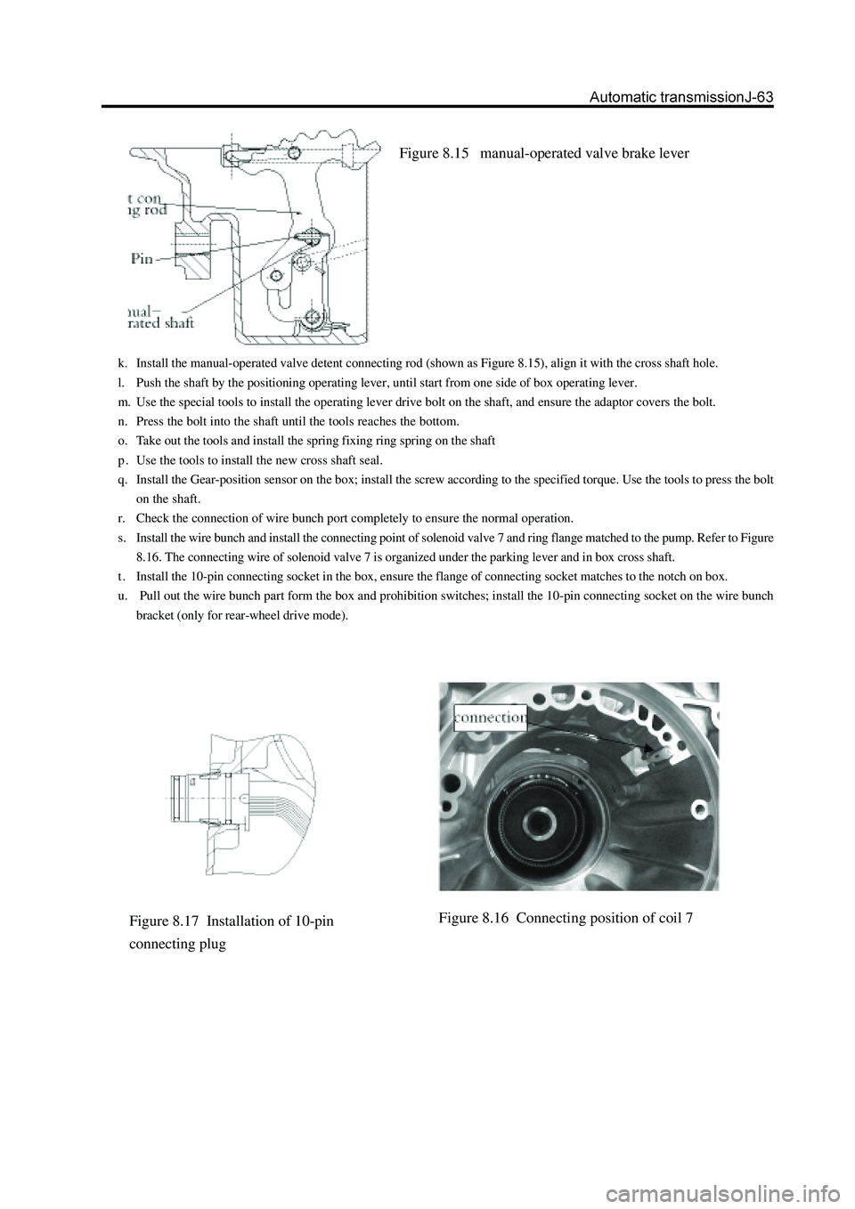
Figure 8.15 manual-operated valve brake lever
k. Install the manual-operated valve detent connecting rod (shown as Figure 8.15), align it with the cross shaft hole.
l. Push the shaft by the positioning operating lever, until start from one side of box operating lever.
m. Use the special tools to install the operating lever drive bolt on the shaft, and ensure the adaptor covers the bolt.
n. Press the bolt into the shaft until the tools reaches the bottom.
o. Take out the tools and install the spring fixing ring spring on the shaft
p . Use the tools to install the new cross shaft seal.
q. Install the Gear-position sensor on the box; install the screw according to the specified torque. Use the tools to press the bolt
on the shaft.
r. Check the connection of wire bunch port completely to ensure the normal operation.
s. Install the wire bunch and install the connecting point of solenoid valve 7 and ring flange matched to the pump. Refer to Figure
8.16. The connecting wire of solenoid valve 7 is organized under the parking lever and in box cross shaft.
t . Install the 10-pin connecting socket in the box, ensure the flange of connecting socket matches to the notch on box.
u. Pull out the wire bunch part form the box and prohibition switches; install the 10-pin connecting socket on the wire bunch
bracket (only for rear-wheel drive mode).
Figure 8.16 Connecting position of coil 7Figure 8.17 Installation of 10-pin
connecting plug
Page 187 of 425
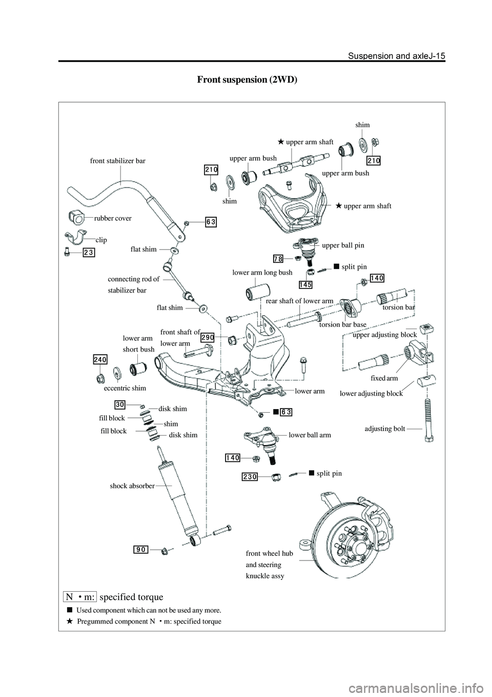
Front suspension (2WD)
front stabilizer bar
rubber cover
clip
connecting rod of
stabilizer bar
flat shim
front shaft of
lower arm
split pin
adjusting bolt
lower adjusting block
fixed arm
upper adjusting block
lower arm
rear shaft of lower arm
torsion bar base
torsion bar
lower arm long bushsplit pin
upper ball pin
upper arm shaft
upper arm bush
flat shim
lower arm
short bush
eccentric shim
disk shim
fill block
fill block
disk shim shim
shock absorbershimshim
upper arm bush
upper arm shaft
lower ball arm
front wheel hub
and steering
knuckle assy
N m: specified torque
Used component which can not be used any more.
Pregummed component N m: specified torque
Page 191 of 425
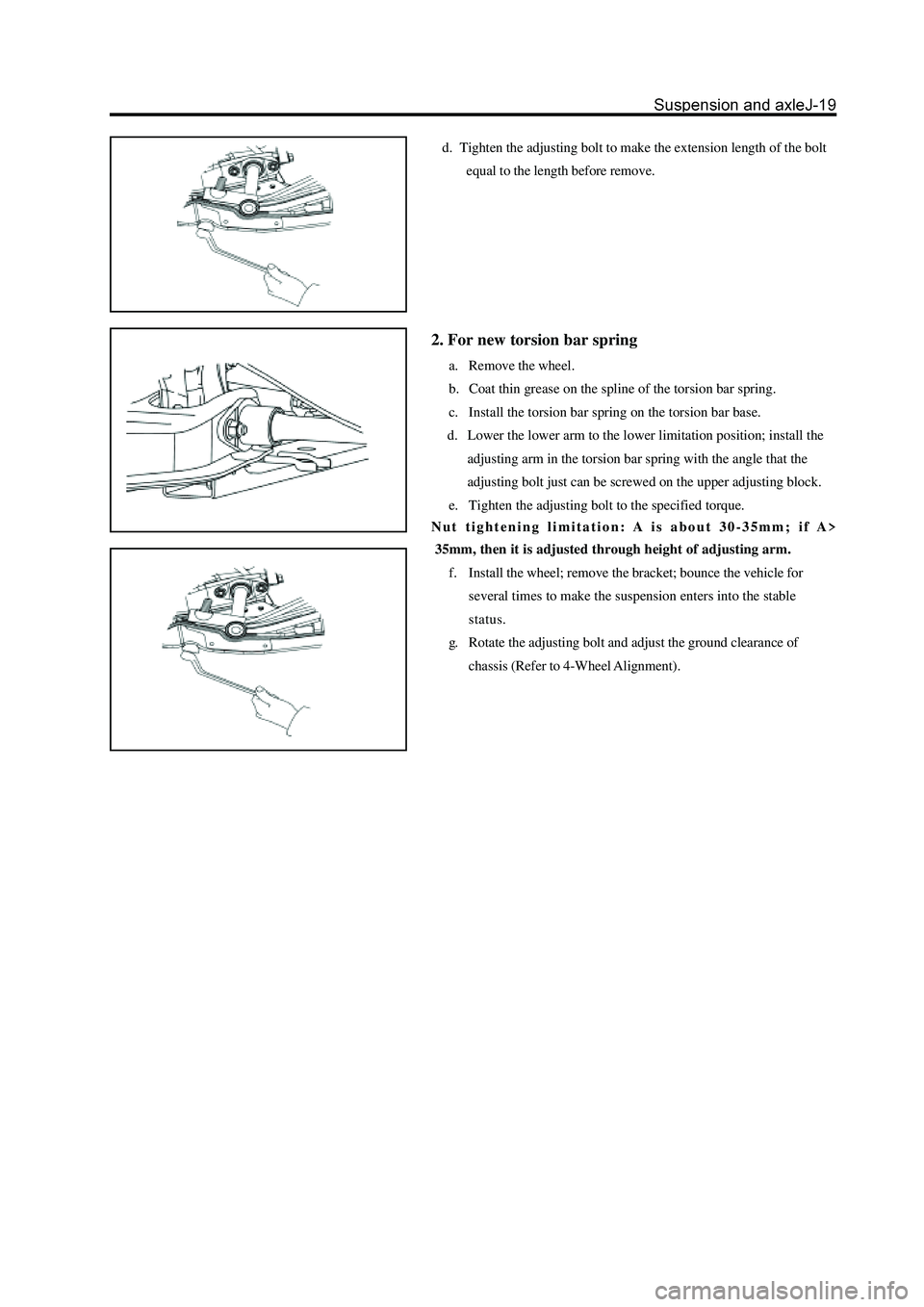
d. Tighten the adjusting bolt to make the extension length of the bolt
equal to the length before remove.
2. For new torsion bar spring
a. Remove the wheel.
b. Coat thin grease on the spline of the torsion bar spring.
c. Install the torsion bar spring on the torsion bar base.
d. Lower the lower arm to the lower limitation position; install the
adjusting arm in the torsion bar spring with the angle that the
adjusting bolt just can be screwed on the upper adjusting block.
e. Tighten the adjusting bolt to the specified torque.
Nut tightening limitation: A is about 30-35mm; if A>
35mm, then it is adjusted through height of adjusting arm.
f. Install the wheel; remove the bracket; bounce the vehicle for
several times to make the suspension enters into the stable
status.
g. Rotate the adjusting bolt and adjust the ground clearance of
chassis (Refer to 4-Wheel Alignment).
Page 199 of 425
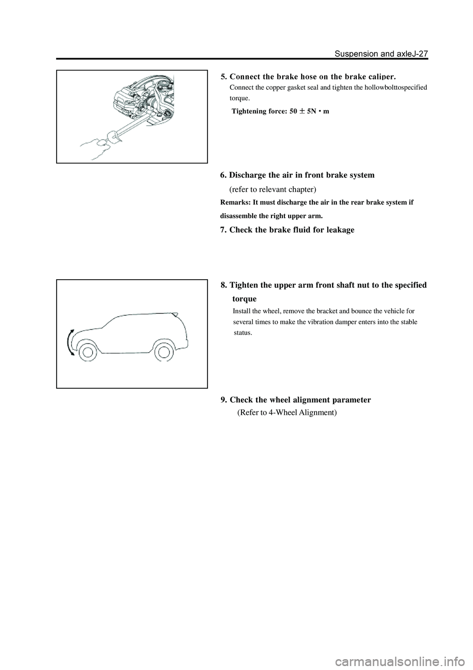
Connect the copper gasket seal and tighten the hollowbolttospecified
torque.
Tightening force: 50
5Nm
6. Discharge the air in front brake system
(refer to relevant chapter)
Remarks: It must discharge the air in the rear brake system if
disassemble the right upper arm.
7. Check the brake fluid for leakage
8. Tighten the upper arm front shaft nut to the specified
torque
Install the wheel, remove the bracket and bounce the vehicle for
several times to make the vibration damper enters into the stable
status.
9. Check the wheel alignment parameter
(Refer to 4-Wheel Alignment)
Page 214 of 425
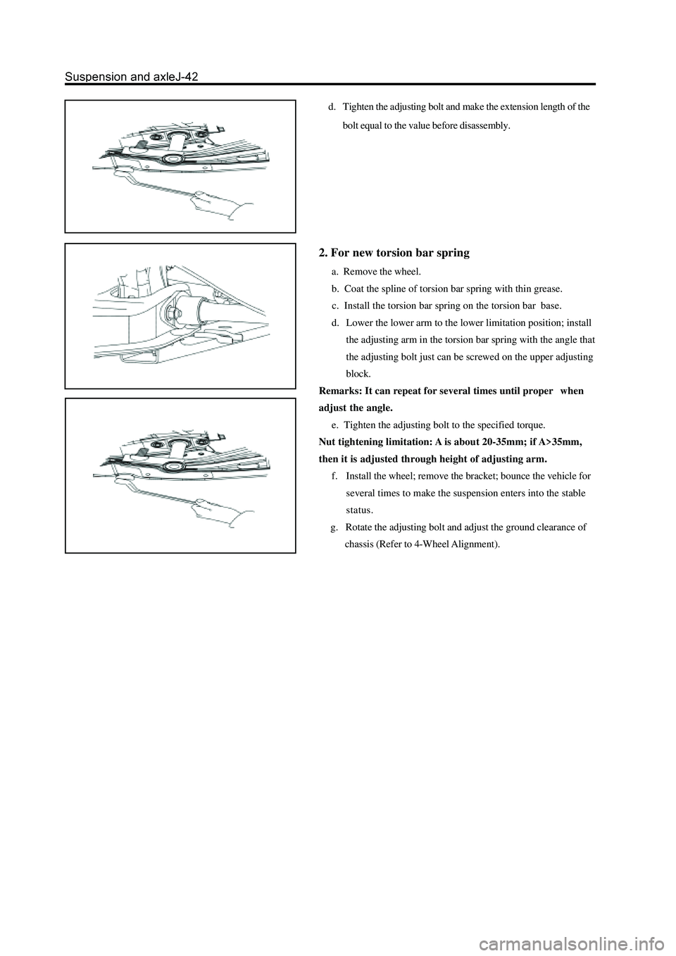
d. Tighten the adjusting bolt and make the extension length of the
bolt equal to the value before disassembly.
2. For new torsion bar spring
a. Remove the wheel.
b. Coat the spline of torsion bar spring with thin grease.
c. Install the torsion bar spring on the torsion bar base.
d. Lower the lower arm to the lower limitation position; install
the adjusting arm in the torsion bar spring with the angle that
the adjusting bolt just can be screwed on the upper adjusting
block.
Remarks: It can repeat for several times until proper when
adjust the angle.
e. Tighten the adjusting bolt to the specified torque.
Nut tightening limitation: A is about 20-35mm; if A>35mm,
then it is adjusted through height of adjusting arm.
f. Install the wheel; remove the bracket; bounce the vehicle for
several times to make the suspension enters into the stable
status.
g. Rotate the adjusting bolt and adjust the ground clearance of
chassis (Refer to 4-Wheel Alignment).
Page 222 of 425
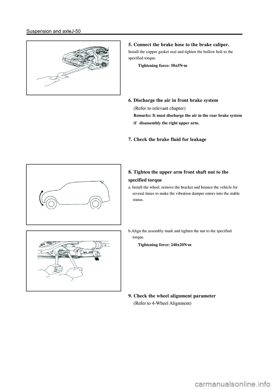
5. Connect the brake hose to the brake caliper.
Install the copper gasket seal and tighten the hollow bolt to the
specified torque.
Tightening force: 50±5N·m
6. Discharge the air in front brake system
(Refer to relevant chapter)
Remarks: It must discharge the air in the rear brake system
i f disassembly the right upper arm.
7. Check the brake fluid for leakage
8. Tighten the upper arm front shaft nut to the
specified torque
a. Install the wheel, remove the bracket and bounce the vehicle for
several times to make the vibration damper enters into the stable
status.
b.Align the assembly mark and tighten the nut to the specified
torque.
Tightening force: 240±20N·m
9. Check the wheel alignment parameter
(Refer to 4-Wheel Alignment)
Page 225 of 425
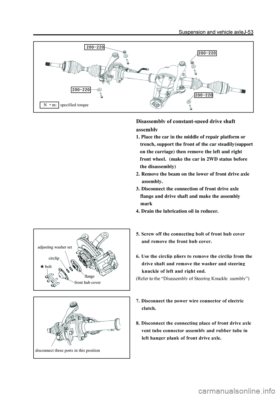
1. Place the car in the middle of repair platform or
trench, support the front of the car steadily(support
on the carriage) then remove the left and right
front wheel. (make the car in 2WD status before
the disassembly)
2. Remove the beam on the lower of front drive axle
assembly.
3. Disconnect the connection of front drive axle
flange and drive shaft and make the assembly
mark
4. Drain the lubrication oil in reducer.
bolt
front hub cover
circlip
adjusting washer set
flange
disconnect three ports in this position
N m: specified torque
Page 246 of 425
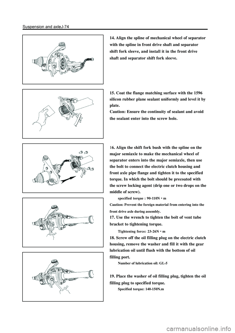
14. Align the spline of mechanical wheel of separator
with the spline in front drive shaft and separator
shift fork sleeve, and install it in the front drive
shaft and separator shift fork sleeve.
15. Coat the flange matching surface with the 1596
silicon rubber plane sealant uniformly and level it by
plate.
Caution: Ensure the continuity of sealant and avoid
the sealant enter into the screw hole.
16. Align the shift fork bush with the spline on the
major semiaxle to make the mechanical wheel of
separator enters into the major semiaxle, then use
the bolt to connect the electric clutch housing and
front axle pipe flange and tighten it to the specified
torque. In which the bolt should be precoated with
the screw locking agent (drip one or two drops on the
middle of screw).
specified torque : 90-110Nm
Caution: Prevent the foreign material from entering into the
front drive axle during assembly.
17. Use the wrench to tighten the bolt of vent tube
bracket to tightening torque.
Tightening force: 23-26Nm
18. Screw off the oil filling plug on the electric clutch
housing, remove the washer and fill it with the gear
lubrication oil until flush with the bottom of oil
filling port.
Number of lubrication oil: GL-5
19. Place the washer of oil filling plug, tighten the oil
filling plug to specified torque.
Specified torque: 140-150N.m