D16y8 HONDA CIVIC 1996 6.G Workshop Manual
[x] Cancel search | Manufacturer: HONDA, Model Year: 1996, Model line: CIVIC, Model: HONDA CIVIC 1996 6.GPages: 2189, PDF Size: 69.39 MB
Page 563 of 2189
Emission Control System
Evaporative Emission (EVAPI Controls (cont'd)
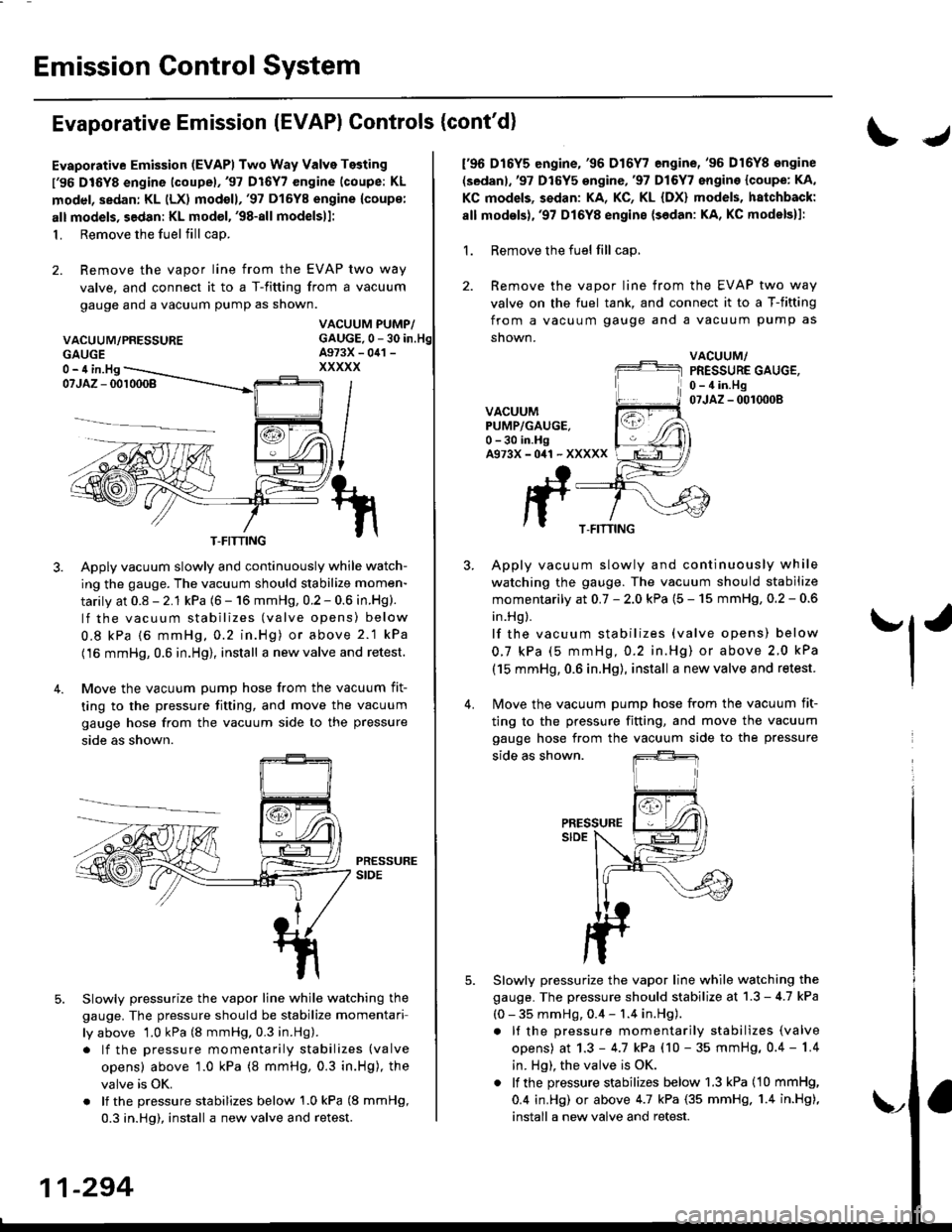
Evaporative Emission (EVAPI Two Way Valve Testing
l'96 DIGYS engine lcoupel,'97 Dl6Y7 engine (coupe: KL
model, sedan: KL (LX) modoll,'97 Dl6Y8 engine {coup€:
alt models, sedan: KL model, '98-all modelsll:
1. Remove the fuel fill cap.
2. Remove the vapor line from the EVAP two way
valve. and connect it to a T-fitting from a vacuum
gauge and a vacuum pump as shown.
VACUUM/PRESSURE
IJ
f96 D16Y5 engine,'96 D16Y7 engine,'96 D16Y8 ongine
(sedanl,'97 D16Y5 engine,'97 Dl6Y7 engine {coupe: KA,
KC models, sedan: KA, KC, KL {DX} models, hatchback:
all modsls),'97 D16Y8 engine {sedan: KA, KC models}l:
1. Remove the fuel fill cap,
2. Remove the vapor line from the EVAP two way
valve on the fuel tank, and connect it to a T-fitting
from a vacuum gauge and a vacuum pump as
snown.
VACUUM/PRESSURE GAUGE,0 - 4 in.Hg07JAZ - 0010008VACUUMPUMP/GAUGE.0 -30 in.HgA973X-041 -XXXXX
Apply vacuum slowly and continuously while watch-
ing the gauge. The vacuum should stabilize momen-
tarily at 0.8 - 2.1 kPa (6 - 16 mmHg, 0.2 - 0.6 in.Hg).
lf the vacuum stabilizes (valve opens) below
0.8 kPa {6 mmHg, 0.2 in.Hg) or above 2.1 kPa
(16 mmHg, 0.6 in.Hg), install a new valve and retest.
Move the vacuum pump hose from the vacuum fit-
ting to the pressure fitting, and move the vacuum
gauge hose from the vacuum side to the pressure
side as shown.
Slowlv pressurize the vapor line while watching the
gauge. The pressure should be stabilize momentari
ly above 1.0 kPa (8 mmHg. 0.3 in.Hg).
. lf the pressure momentarily stabilizes (valve
opens) above '1.0 kPa (8 mmHg, 0.3 in.Hg), the
valve is OK.
. lf the pressure stabilizes below 1.0 kPa (8 mmHg,
0.3 in.Hg), install a new valve and retest.
Apply vacuum slowly and continuously while
watching the gauge. The vacuum should stabilize
momentarily at 0.7 - 2.0 kPa (5 - 15 mmHg, 0.2 - 0.6
in.Hg ).
lf the vacuum stabilizes (valve opens) below
0.7 kPa (5 mmHg,0.2 in.Hg) or above 2.0 kPa
(15 mmHg, 0.6 in.Hg), install a new valve and retest.
Move the vacuum pump hose from the vacuum fit-
'l'
4.
5.
ting to the pressure fitting, and move the
gauge hose from the vacuum side to the
side as shown.
PRESSURESIDE
Slowly pressurize the vapor line while watching the
gauge. The pressure should stabilize at 1.3 - 4.7 kPa
(0 - 35 mmHg, 0.4 - 1.4 in.Hg).
. It the pressure momentarily stabilizes (valve
opens) at 1.3 - 4.7 kPa (10 - 35 mmHg, 0.4 - 1.4
in. Hg), the valve is OK.
. lf the pressure stabilizes below 1.3 kPa (10 mmHg,
0.4 in.Hg) or above 4.7 kPa (35 mmHg. 1.4 in.Hg),
install a new valve and retest.
vacuum
pressure
GAUGE0- 4 in.Hg
T-FITTINGT-FITTING
11-294
\,
Page 586 of 2189
Transmission Assembly
Removal (cont'dl
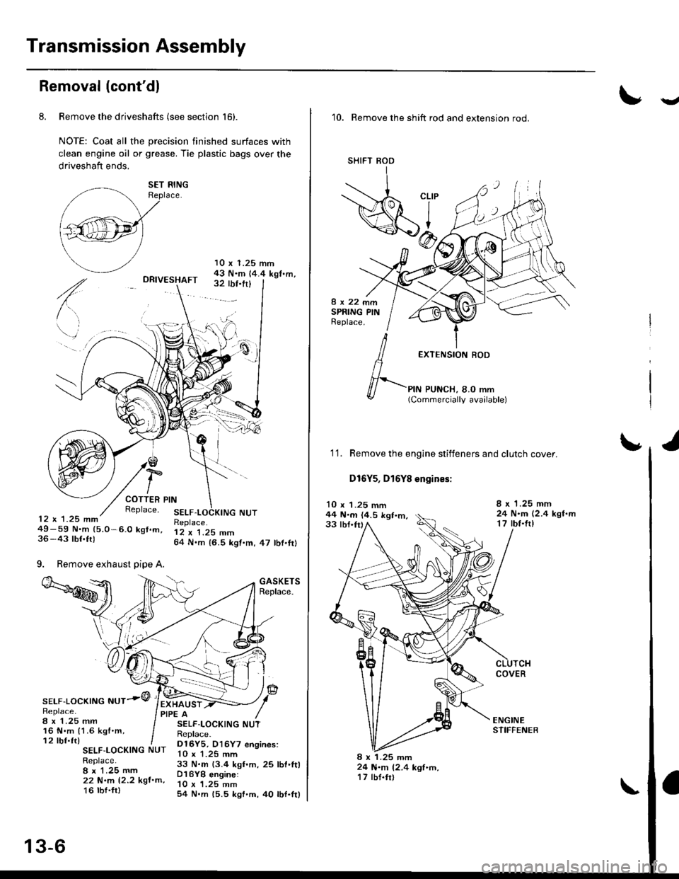
8. Remove the driveshafts (see section 161.
NOTE: Coat all the precision finished surfaces with
clean engine oil or grease. Tie plastic bags over the
driveshaft ends,
DRIVESHAFT
10 x 1.25 mrn43 N.m 14.4 kgt.m,32 rbf.frl
COTTER PINReplace. SELF12 x 1.25 mm49-59 N.m (5.0 -6.0 kgt.m,36-43 lbf.ft)
9. Remove exhaust pipe A.
Replace.12 x 1.25 mm64 N.m {6.5 kgt.m,47 lbf.tr)
GASKETSReplace.
IF\sELF-LocKtNG NUT.''1/Replace.8 x 1.25 mm16 N.m {1.6 kgf'm,12 tbf.ft)
EXHAUSTPIPE A
SELF-LOCKING NUTReplace.I x 1.25 mm22 N.m (2.2 kgf.m,16 tbt'fr)
SELF-LOCKING NUTReplace.D16Y5, D16Y7 engines:
33 N.m {3.4 kgf.m,25 lbt.ft)D16YB engine:10 x 1.25 mm54 N.m 15.5 kgl'm,40 lbf.ttl
SET RING
13-6
v'10. Remove the shift rod and extension rod.
SI'IIFT BOD
8x22mmSPRING PINReplace.
EXTENSION ROD
PIN PUNCH, 8.O mm(Commercially available)f-
'1'1. Remove the engine stiffeners and clutch cover.
D16Y5, D16Y8 engines:
10 x 1.25 mm44 N.m (4.5 kgt.m,33 tbf.tr)
I x 1.25 mm24 N.m (2.4 kgf.m17 lbt.frl
COVER
8 x 1.25 mm24 N.m 12.4 kgf'tn,17 tbt.tr)
Page 591 of 2189
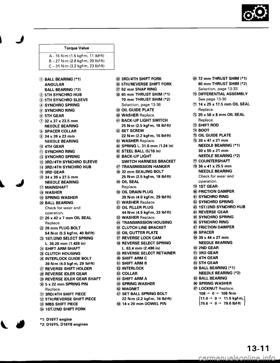
Torque Value
A - 15 N.m (1.5 kgf.m, 1'1 lbf.ft)
B - 27 N.m (2.8 kgf.m. 20 lbift)
C - 31 N.m {3.2 kgnm, 23 lbift)
\
O BALL BEARING (*T)
ANGULAR
BALL BEARING {*2I
O 5TH SYNCHRO HUB
O 5TH SYNCHRO SLEEVE
€) SYNCHRO SPRING
o SYNCHRO B|NG
@ 5TH GEAR
@ gz xgt x 23.5 mm
NEEDLE BEARING
@ SPACER COLLAR
@34x39x23mm
NEEDLE BEARING
(D 4TH GEAR
O SYNCHRO RING
C) SYNCHRO SPRING
CO 3RD/4TH SYNCHRO SLEEVE
@ 3RD/4TH SYNCHRO HUB
(} 3RD GEAR
@34x39x27.5mmNEEDLE BEARING
G) MAINSHAFT
G) WASHER
@ SPRING WASHER
@ BALL BEARING
Check for wear and
operation.(E 26x42x7 mm OIL SEAL
Replace.
@ 28 mm PLUG BOLT
5,1 N.m {5.5 kgf'm, /t0 lbt'ft)
@ lsT/zND SELECT SPRING
L. 36.26 mm (1./P8 in)
@ SHIFT ARM SHAFT
@ CLUTCH HOUSING
@ INTEELOCK GUIDE BOLT
39 N.m (4.0 kgf.m, 29 lbf.ftl
@ REVERSE SHIFT HOLDER
@ REVERSE IDLER GEAR
@ REVERSE IDLER GEAR SHAFT
@ 5 x 22 mm SPRING PIN
Replace.
@ 3RD/4TH SHIFT PIECE
@ 5TH/REVERSE SHIFT PIECE
@ MBS SHIFT PIECE
@ 1ST/2ND SHIFI FORK
*1:D16Y7 engine*2: D16Y5, D16Y8 engines
@ 3RD//|TH SHIFT FORK
@ 5TH/REVERSE SHIFT FORK
@ 52 mm SNAP RING
@ 65 mm THRUST SHIM (*11
70 mm THRUST SHIM (*21
Selection, page 13-36
@ OIL GUIDE PLATE
@ wASHER Replace.
@ BACK.UP LIGHT SWITCH
25 N.m (2.5 kgf'm, 18 lbf'ft)
@ sET SCREW
22 N.m {2.2 kgf.m, 16 lbl.ft}
@ WASHER Replace.
@D SPRING 1.31.6 mm (1.2,1inl
@ STEEL BALL 15/16 in)
@ BACK-UP LIGHT
SWITCH HARNESS BRACKET
@ TRANSMISSION HANGER
@ 32 MM SEALING BOLT
25 N.m (2.5 kgf.m, 18 lbt'ft)
@ OIL SEAL
Replace.
@ OIL DRAIN PLUG
39 N.m (4.0 kgf.m, 29 lbf.ft)
@ WASHER Replace.
@} OIL FILLER PLUG
44 N.m (4.5 kgf.m, 33 lbf'ftl
@ WASHER Replace.
@) TRANSMISSION HOUSING
€) CLUTCH LINE BRACKET
@ OIL GUTTER PLATE
@ REVERSE LOCK CAM
@ REVEBSE SELECT SPRING
L. 63.4 mm {2.,196 in)
@ REVERSE SELECT RETAINER
@ SHIFT ARM C
@ SHIFT ARM B
@ INTERLoCK
@ COLLAR
@ SHIFT ARM A
@ SPRING WASHER
@ MAGNET
@ sET BALL SPRING BOLT
22 N.m (2.2 kgf.m, 16 lbf.ftl
@ 14 x 20 mm DOWEL PIN
@ 72 mm THRUST SHIM l*11
80 mm THRUST SHIM (*21
Selection, page '13-33
@ DIFFERENTIAL ASSEMBLY
See page 13-30
@ 14 x 25 x 17.5 mm OIL SEAL
Replace.
@ 35 x 56 x 8 mm OIL SEAL
Replace.
@ SHIFT ROD
@ BOOr
@ OIL GUIDE PLATE
@30x47x21 mm
NEEDLE BEARING (* 1}
30x55x21 mm
NEEDLE BEARING {'2)
@ COUNTERSHAFT
@36x41 x 25.5 mm
NEEDLE BEARING
Check for wear and
operatron.
@ lsT GEAR
@ FRICTION DAMPER
@ SYNCHRO RING
@ SYNCHRO SPRTNG
@ lST/2ND SYNCHRO HUB
@ REVERSE GEAR
@ SYNCHRO SPRING
@ SYNCHRO RING
@ FRICTION DAMPER
@ SPACER
@39x4lx27mm
NEEDLE BEARING
@ 2ND GEAR
@ 3RD GEAR
@ 4TH GEAR
@ sTH GEAR
@) BALL BEARING {* 1}
NEEDLE BEARING (*2}
@ BALL BEARING
@) SPRING WASHER
@ LoCKNUT Replace.
108 - 0- 108 N.m
ftt.o* o- 1r.o kst.m,l
179.6- 0- 79.6 rbtft I
13-1 1
Page 595 of 2189
Mainshaft Assembly
I
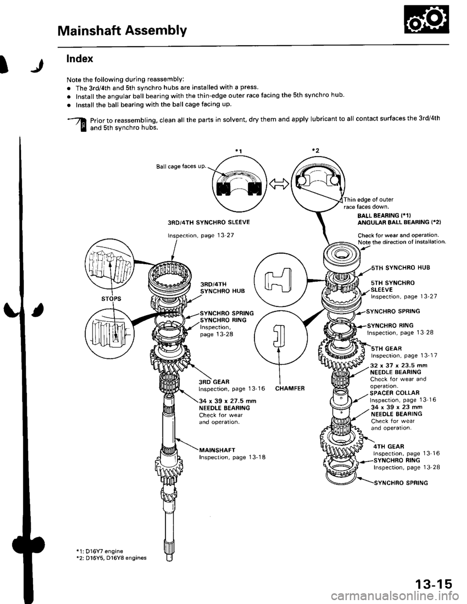
lndex
Note the following during reassembly:
. The 3rd/4th and sth svnchro hubs are installed with a press
. Install the angular ball bearing with the thin-edge outer race facing the sth synchro hub
. Install the ball bearing with the ball cage facing up
prior to reassembling, clean all the parts in solvent, dry them and apply lubricant to all contact surfaces the 3rd/4th
and sth svnchro hubs.
Ballcage faces uP.
Thin edge of outerrace laces down.
3RD/4TH SYNCHRO SLEEVE
page 13'27
SYNCHRO SPRINGSYNCHRO RINGInspection,page 13-28
BALL BEARING {*1)ANGULAR BALL BEARING ('2)
Check for wear and operataon.Note the direction ot installation
5TH SYNCHROSLEEVElnspection, page 13-27
SYNCHRO HUB
SYNCHRO RINGInspection, pase 13 28
sTH GEARInspection, page 13-17
3RD GEARlnspection, page 1 3-1 6
34 x 39 x 27.5 mmNEEDLE BEARINGCheck for wearano opetaflon,
MAINSHAFTInspection, page 13-18
CHAMFEB
32 x 37 x 23.5 mmNEEDLE BEARINGCheck for wear andoperation.SPACER COLLABInspection, page 1316
34x39x23mmNEEDLE EEARINGCheck for wearand operation,
4TH GEARrnspeclron,
*1: D16Y7 engine*2: D16Y5, D16Y8 engines
page 13'16RINGInspectaon, page 13 28
SPRING
13-15
Page 599 of 2189
I
)r'
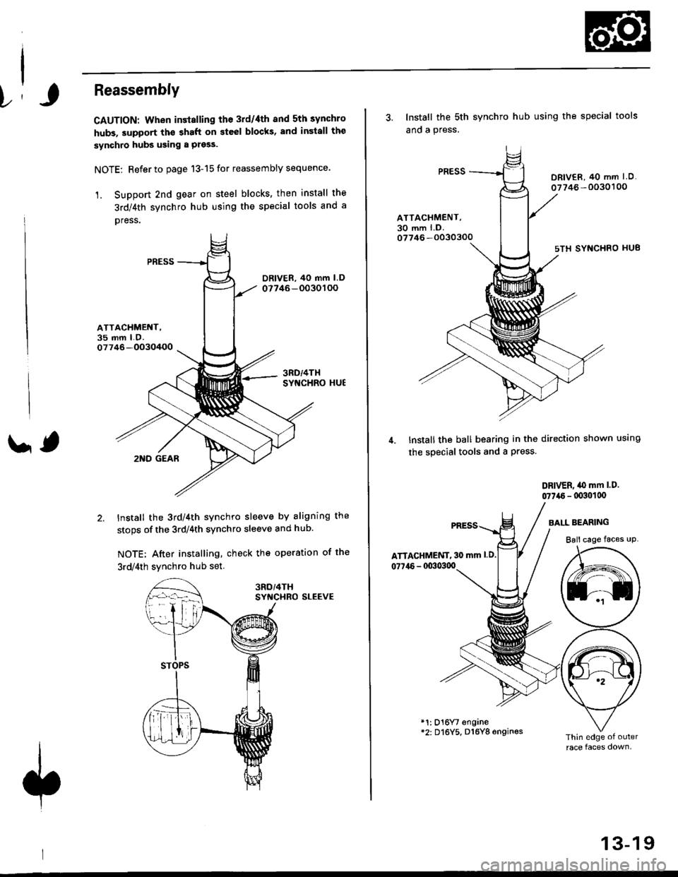
Reassembly
CAUTION: When installing the 3rd/4th and 5th synchro
hubs, support th€ shaft on steel blocks, and insiall the
synchro hubs using a press.
NOTE: Refer to page 13-15 for reassembly sequence.
1. Support 2nd gear on steel blocks' then install the
3rd/4th synchro hub using the special tools and a
oress.
ATTACHMENT,35 mm LO.07746-OO3O/+OO
' ,2I{D GEAR
Install the 3rd/4th synchro sleeve by aligning the
stops of the 3rdl4th synchro sleeve and hub.
NOTE; After installing, check the operation of the
3rd/4th svnchro hub set
SYf{CHRO SLEEVE
3. Install the sth
ano a press.
synchro hub using the special tools
DRIV€R, 40 mm I O.
07746 -0030'�100
ATTACHMENT,30 mm l.D.07746 -O030300
sTH SYNCHRO HU8
Install the ball bearing in the direction shown using
the special tools and a Press.
DRIVER, iO mm l.D.
07746 - lxxlollx'
ATTAGHMENT, 30 mm l.D.
077i16 - 00303qt
BAI-L BEARING
Ball cage faces uP
*1: D16Yt engane*2: Dl6Y5, D16Y8 6ngines
13-19
Page 600 of 2189
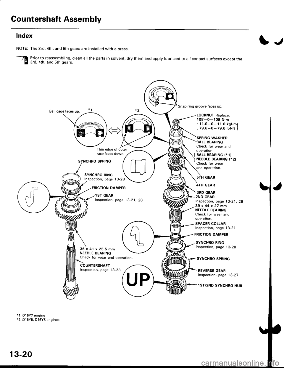
Countershaft Assembly
Index
I.r
NOTE:
-re
The 3rd, 4th, and sth gears are installed with a press.
Prior_to reassembling, clean all the parts in solvent, dry them and apply lubricant to all contact surfaces except the3rd, 4th, and 5th gears.
Snap ring groove faces up.
LOCKNUT Replace.108-O- 108 N.m
I 11.0-O-11.0 kst.ml
I 79.6-0- 79.6 lbt.ft I
SYNCHRO SPRING
SYNCHRO RINGInspectaon, page 13-28
FRICTION DAMPER
Thin edge ol outerrace faces down.
Check for wear andoperatron,
/ BALL EEAR|NG t*1)
t NEEDLE BEARTNG (.2)
Check for wearand operatron,
WASHERBEARING
GEAR
4TH GEAR
3RD GEAR2ND GEAR
FRICTION DAMPER
SYNCHRO SPRING
SYNCHRO RINGInspection, page 13-2836 x 41 x 25.5 mmNEEDLE BEARINGCheck for wear and operataon.
Inspection, page 13-23
1ST GEARlnspection, page 13 21, 28lnspection, page 13-21, 2839x44x27m�mNEEDLE BEARIfI'GCheck for wear andoperation.
SPACER COLLARInspection, page 13-21
REVERSE GEARlnspection, page 13 27
1ST/2ND SYNCHRO HUB
*1: D'16Y7 engine*2: D16Y5, D16Y8 engines
13-20
Page 604 of 2189
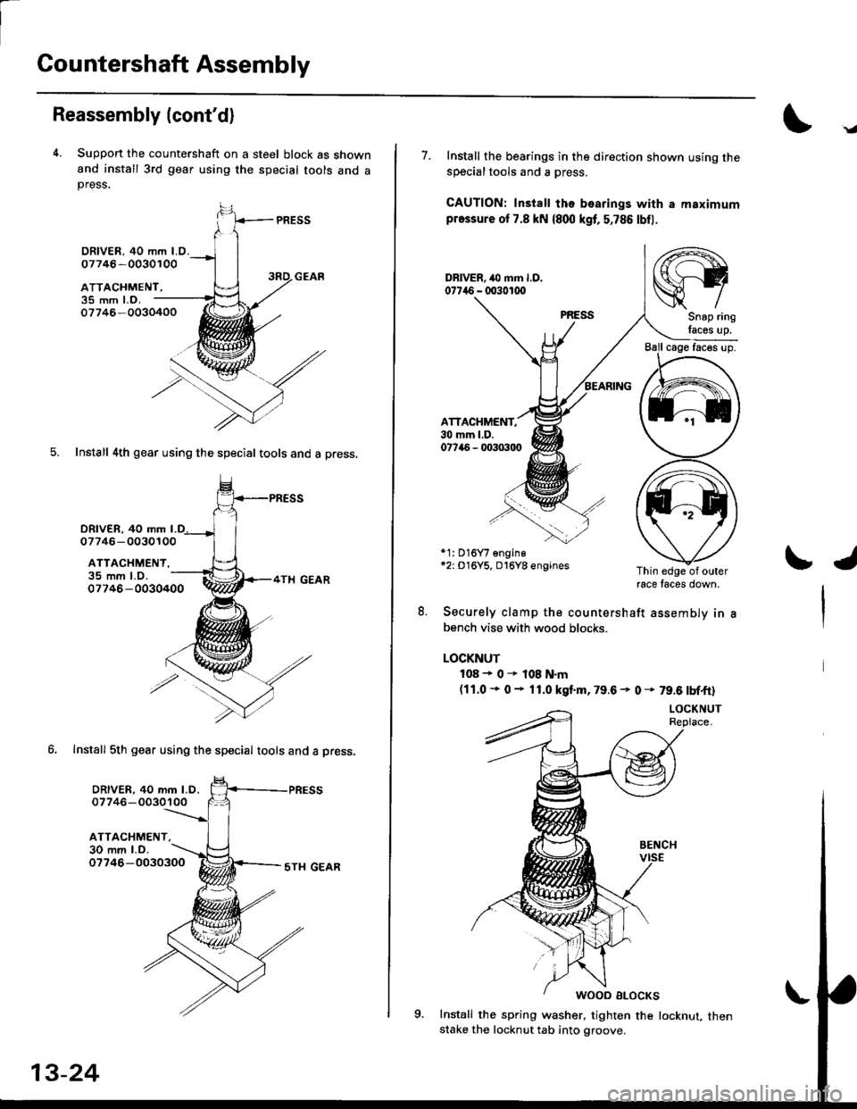
Countershaft Assembly
Reassembly (cont'd)
4. Suppon the countershaft on a steel block as shownand install 3rd gear using the special tools and apress.
PRESS
35 mm l.o.07746-0030400
5. Install 4th gear using the special tools and a press.
DRlvER. 40 mm
DRIVER, 40 mm LO.07746 -0030100
ATTACHMENT,
07746- 0030100
ATTACHMENT,
DRIVER, 40 mm l.D.07746-0030100
ATTACHMENT,30 mm l.D.
35 mm LO.07746-0030400
6. Install 5th gear using the special tools and a Dress.
07746-00303005TI{ GEAR
.g
7. Install the bearings in the direction shown using thesDecialtools and a oress.
CAUTION: Install ths bearings with a maximumpressure ot 7.8 kN {800 kgt, 5,786 lbfl.
ATTACHMENT,30 mm l.D.07745 - q'303tl)
*1: 016Y7 engine*2: D16Y5, D16Y8 enginesThin edge of outerrace faces down,
8. Securely clamp the countershaft assemblv in
bench vise with wood blocks.
LOCKNUT
108+0r108N.m(11.0 * 0 - 11.0 kgt m. 79.6 - 0 * 79.6 tbf.ft)
Install the spring washer, tighten the locknut, thenstake the locknut tab into groove.
/rt-\
srySnap ring
lacss up.
\J
Page 613 of 2189
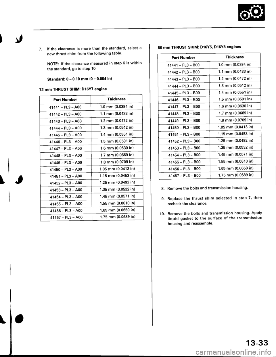
7. lf the clearance is more than the standard, select a
new thrust shim from the following table
NOTE: It the clearance measured in step 6 is within
the standard. go to step 10.
Standard: 0 - 0.10 mm l0 - 0.00/t inl
72 mm THRUST SHIM: D16Y7 engin€
\
Part NumberThickness
41441 - PL3 - A001.0 mm (0.0394 in)
41442-PL3-A00'1 .1 mm {0.0433 in)
41443-PL3-A001.2 mm {0.0472 in)
41444-PL3-A001.3 mm (0.0512 in)
41445-PL3-A001.4 mm (0.0551 in)
41446-PL3-A001.5 mm (0.0591 in)
41447-PL3-A001.6 mm (0.0630 in)
41448-PL3-A001.7 mm (0.0669 in)
4r449-PL3-A001.8 mm (0.0709 in)
41450-PL3-A001.05 mm {0.0413 in)
41451-PL3-A001.15 mm (0.0453 in)
41452-PL3-A001.25 mm (0.0492 in)
41453-PL3-A001.35 mm (0.0532 in)
41454-PL3-A00'1.45 mm (0.057'l in)
41455-PL3-A001.55 mm (0.0610 in)
41456-PL3-A001.65 mm (0.0650 in)
41457-PL3-A001.75 mm (0.0689 in)
80 mm THBUST SHIM: D16Y5. D16Y8 engines
Remove the bolts and transmission housing.
Replace the thrust shim selected in step 7, then
recheck the clearance.
Remove the bolts and transmission housing. Apply
liquid gasket to the surface of the transmission
housing and reassemble
8.
9.
10.
Part NumbelThickness
41441 - PL3 - B001.0 mm (0.0394 in)
41442-PL3-8001.1 mm (0.0433 in)
41443-PL3-8001.2 mm (0.0472 in)
41444-PL3-8001.3 mm (0.0512 inl
41445-PL3-8001.4 mm (0.0551 in)
41446-PL3-8001.5 mm (0.0591In)
41447-PL3-8001.6 mm (0.0630 in)
4r 448 - PL3 - 8001.7 mm (0.0669 in)
4 t449 - PL3 - 8001.8 mm (0.0709 in)
41450-PL3-800'1.05 mm (0.0413 in)
41451 - PL3 - 800'1.15 mm (0.0453 in)
41452-PL3-8001.25 mm (0.0492 in)
41453-PL3-B001.35 mm (0.0532 in)
41454-PL3-B001.45 mm (0.0571 in)
41455-PL3-B001.55 mm (0.0610 in)
41456-PL3-8001.65 mm (0.0650 in)
41457-PL3-8001.75 mm {0.0689 in)
Page 615 of 2189
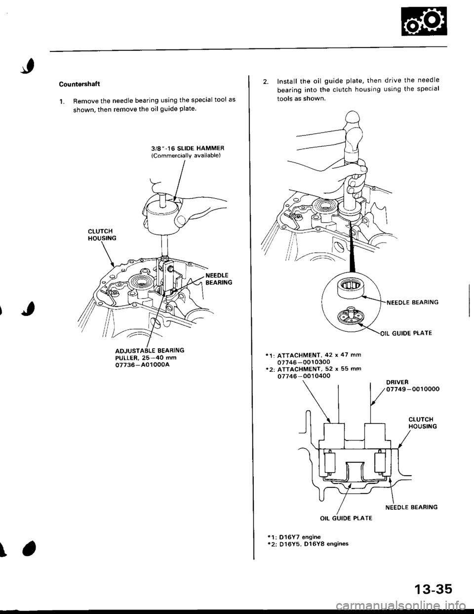
Cou ntershaft
1. Remove the needle bearing using the special tool as
shown. then remove the oil guide plate
3/g " -16 SLIDE HAMMER
{Commercially available)
PULLER, 25-40 mm07736-AO1000A
\
2. Install the oil guide Plate, then
bearing into the clutch housing
tools as shown.
d rive the needle
using the special
'1: ATTACHMENT, 42 x 47 mm
07746-0010300*2: ATTACHMENT, 52 x 55 mm
07746 -0010400
ORIVER07749 -0010000
CLUTCHHOUSING
NEEOLE BEAFING
GUIDE PLATE
NEEOLE BEARING
*1: D16Y7 enqine*2: D16Y5, D16Y8 engines
OIL GUIDE PTATE
13-35
Page 800 of 2189
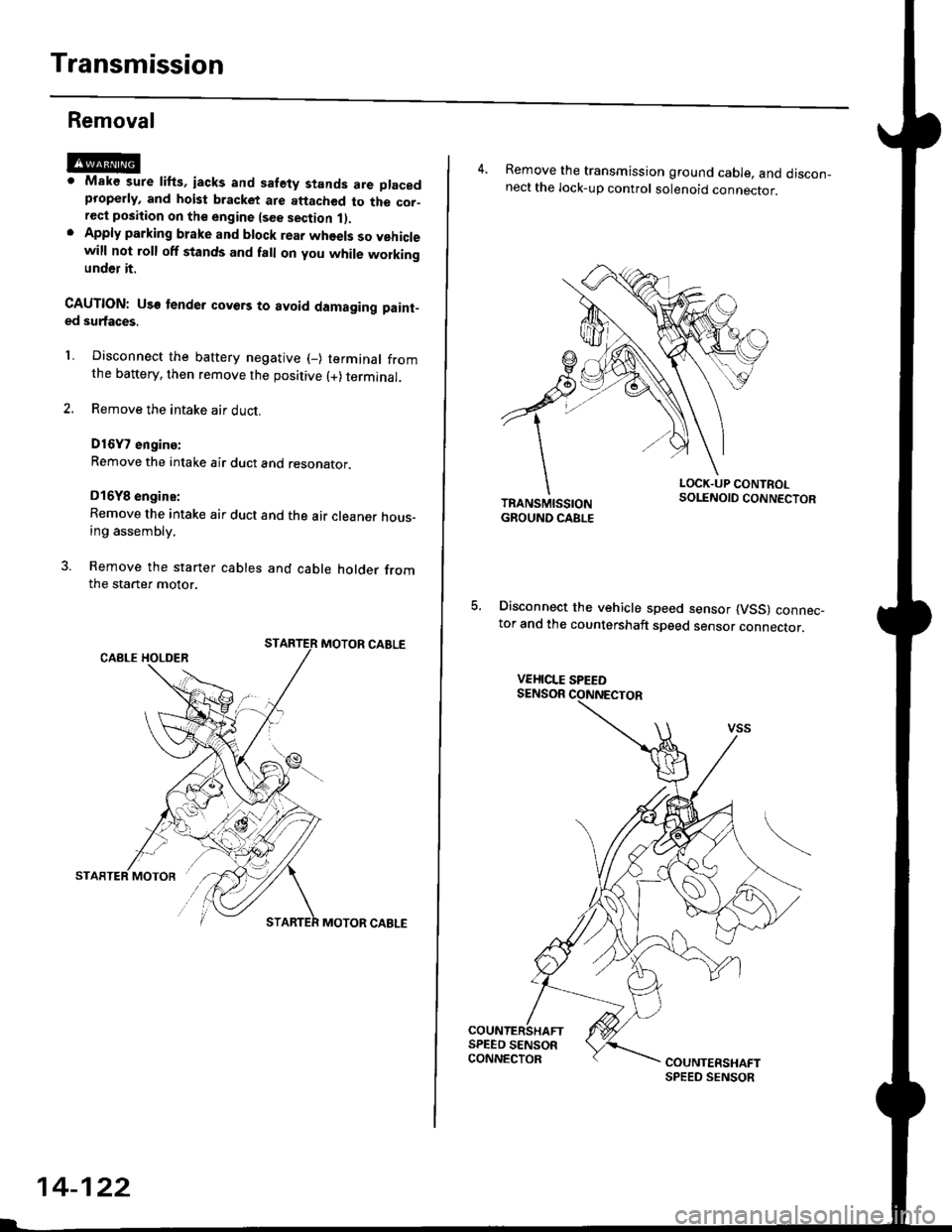
Transmission
Removal
@Maks sure lifts, iacks and safety stands are placedproperly, and hoist bracket ate aftached to the cor_rec{ position on the engine lsee section 1).Apply parking brake and block rear whoels so vehiclewill not roll off stands and fall on you while workingunder it.
CAUTION: Use tender covers to avoid damaging paint-ed surfaces.
1, Disconnect the battery negative (_) terminal fromthe battery, then remove the positive (+) terminal.
2. Remove the intake air duct.
D16Y7 engins:
Remove the intake air duct and resonator.
D16Y8 engine:
Remove the intake air duct and the air cleaner hous-ing assembly,
3. Remove the starter cables and cable holder fromthe starter motor.
MOTOR CABLE
MOTOR CABLE
14-122
4. Remove the transmission ground cable, and discon_nect the lock-up control solenoid connector.
LOCK.UP CONTROLSOLENOID CONNECTOR
5, Disconnect the vehicle speed sensor (VSS) connec_tor and the countershaft speed sensor connector.
VEHICLE SPEED