engine ground HONDA CIVIC 1996 6.G Workshop Manual
[x] Cancel search | Manufacturer: HONDA, Model Year: 1996, Model line: CIVIC, Model: HONDA CIVIC 1996 6.GPages: 2189, PDF Size: 69.39 MB
Page 1961 of 2189
- How the Circuit Works
Radiator Fan
Voltage is provided at all times to the radiator fan
relay (contacts) through fuse 57. With the ignition
swilch in ON (ll), voltage is provided to the coil of
the relay through luse 17.
The radiator tan relay can be grounded through
either the engine coolant temperature switch or the
engine control module (ECM) or powertrain control
module (PCM).
The engine coolant temperature switch grounds
the radiator fan relay (coil) when the engine
coolant temperature exceeds 199'F (83'C). The
switch opens when coolanl temperature
decreases 3'- 8'C.
Condenser Fan
Voltage is provided at all times to the condenser fan
relay (contacts) through fuse 56. With the ignition
switch in ON (ll), voltage is provided to the coil of
the relay through fuse 17. When you push the A'lC
switch and put the heater fan switch in 1, 2,3, o( 4
position, the ly'C thermostat comes on, the
condenser fan relay energizes, and the condenser
fan motor runs.
A,/C Thermostat
The A,/C thermostat is located on the evaporator
housing. The A,/C thermostat tums off the A/C
compressor clutch if the temperature at the
evaporator goes below 3'C (37'F). This prevents
condensation from freezing on the evaporator fins
and blocking the air delivery into the passenger
compartment. lf the temperature goes below 3'C
(37"F) tuming off the Ay'C thermostat, ground will be
removed from the condenser fan relay. This will
deenergize the relay and remove voltage from the
condenser fan motor causing the fan to stop running.
Reter to the Service Manual (Section 23, Eleckical)
for specific tests or troubleshooting procedures.
63-3
Page 1969 of 2189
Brake System Indicator Light (cont'd)
- How the Circuit Works
The brake system indicator light comes on to alert
the driver that the parking brake is applied, or that
the brake fluid level is low. lt also comes on as a
bulb test when the engine is cranked.
Parking Brake
With the ignition switch in ON (ll) or START (lll),
voltage is applied through fuse 25 to the brake
system light. When you apply the parking brake, the
switch closes and provides a ground for the light.
The light then comes on to remind you that the
parking brake is applied.
Brake Fluid Level
With the ignition switch in ON (ll) or START (lll),
voltage is applied through fuse 25 to the brake
system light. lf the brake fluid level is low, the brake
fluid level switch closes, providing ground to the
circuit. The brake system light then comes on,
alerting the d verto a low brake fluid level in the
brake master cylinder. (Check brake pad wear
before you add fluid).
Bulb Check
With the ignition switch in START (lll) and clutch
pedal depressed or A'lT gear selector in PARK (P)
or NEUTRAL (N), voltage is applied through fuse 31
to the brake bulb check circuit. The brake bulb
check circuit closes, allowing current to flow through
the brake system light and bulb check circuit to
ground. The brake system light then comes on to
test the bulb.
Refer to the Service Manual (Section 23, Electrical)
for specific tests or troubleshooting procedures.
71-2
a
\fa
Page 2072 of 2189
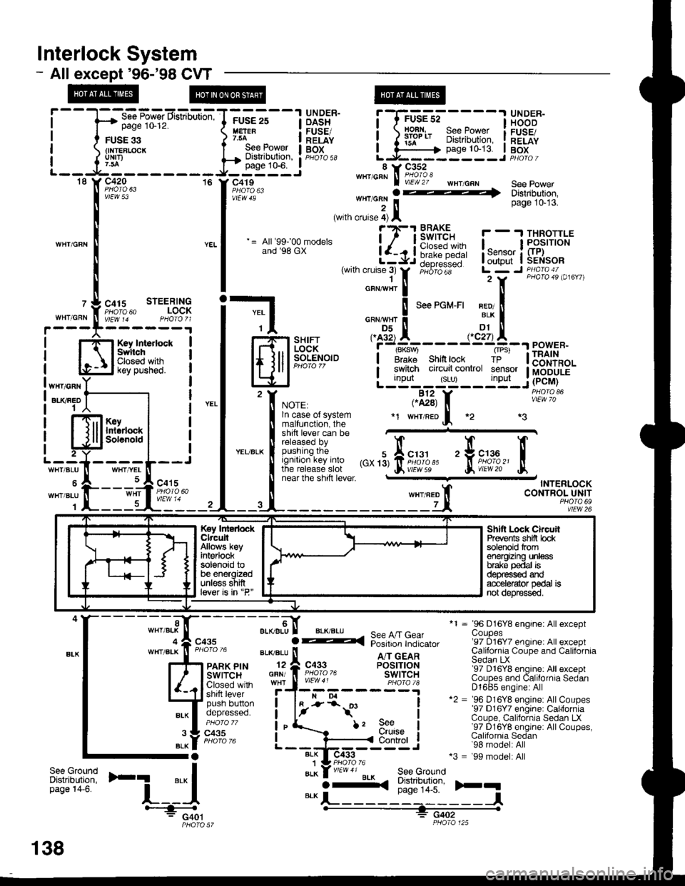
lnterlock System
- Allexcept'96-'98 CVT
page 10-12.
FUSE 33{INTEBLCICKuNrI)
WHIICRN
OASH I HOOD
H:" - IlEiE" i ) iifl* 8i?[',ffii i[".tfi
;GE-st----l glD^:R-
page 10-13. I BoxL.J------ --J PHotoi
*1 = 96 D16Y8 engine: Allexceptuoupes'97 D16Y7 engine: All exceptCalifornia Coupe and CaliforniaSedan LX'97 D16Y8 engine: All exceptCoupes and Calilornia SedanD1685 engine: All*2 = '96 D16Y8 engine: AllCoupes'97 D16Y7 engine: CaliforniaCoupe, California Sedan LX'97 D16Y8 englne: AllCoupes,Calilornia Sedan'98 model: All*3 = '99 model: All
)rq
,'",:[*nu'
=-CF'!,n:E!-l
Hfl*gff* i
l#?;"'" -,,;:::?i-ili:itlll:
|
= lr.u:;.Br-* i-{Ji6i1!-- !,*;L$il{:*
|
,wrn cruse;r
tr,
;"6;dii-- Lr7 r ii\l,B".i o,",,,
i-l o,"*",!
'""'o*-'' x?!
| -$-.",., .^AX-----.,'dtA--"^",."
lfl.iil F]iH*,"'i''t#'---.r=23[11
eowen.
lElJP-".'.'
-
L;tT'#:yTltijF.iu.'f, *or., ,.il3, f, iii"^'?o'
| !^:?::^?l:t:9" *r w'raeof, *2 *3
t:l*ii** ffi"""'"
! fit:'/:,:iffJff ,",'3,fii;1,1,'' 'trii'df,'
tr
I near lne snrn rever - TNTERLOCK
ll wxrneo t CONTROL UNIT
--4-------------Lt, *?,1fl92
T-----1 UNDER-FUSE 25
See Power I BOtDisilibution, : pHb'ro ss
.----
'[il:'ff*,,,,**
., J*:]l ., '"*""
;.-9,[ aL(BLU
GFN/
I
See A/T GearPosition Indicator
A/T GEARPOSITIONswtTcHc433
BLK I-
i-*t'
BLK1BLK
f, 9e€urutse
I
I
I
IControl
ilt:tfi'F1
'-i_:{BLKO-<(
See GroundDistribution,page 14-5.
-l#: G401PHO|O 57
Key IntedockClrcuitAllows keyint€rlocksolenoid tobe energizedunless shiftlever is in "P"
Shltt Lock ChcuilPrevents shifi bcksolenoid tromenergizing unlessbrake p€dal isd€pfessed ardacc€le{ator pedal isnot depr€ssed.
";t-,".f";,
138
Page 2110 of 2189
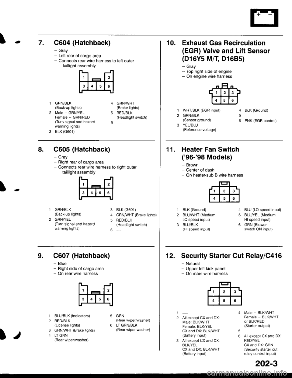
\7. C604 (Hatchback)
GRN/BLK(Back-up lights)
l\4ale GRNIYELFemale - GRN/RED(Turn signaland hazardwarning lights)
BLK (G601)
- Gray- Left rear ol cargo area- Connects rear wire harness to left outer
taillight assembly
4
5
6
1
2
GRNAVHT(Brake lights)
FED/BLK(Headllght switch)
10. Exhaust Gas Recirculation
(EGR) Valve and Lift Sensor
1
2
3
(D16Y5 MfI D1685)
- Gray- Top right side of engine- On engine wire harness
WHT/BLK (EGR input)
GRN/BLK(Sensor ground)
YEUBLU(Reference voltage)
4
5
6
BLK (Ground)
PNK (EGR control)
of cargo area
rear wire harness to right outer
assembly
n- -n
a t | _ a2a
l3I4t5tttl
IJ
I
8. C605 (Hatchback)
- Gray- Right rear- Connects
taillight
GRN/BLK(Back-up lights)
GRNTYEL(Turn signaland hazardwarning lights)
3
4
5
6
1
2
BLK (G601)
GFNAVHT (Brake lights)
RED/BLK(Headlight switch)
11. Heater Fan Switch
('96-'98 Models)
- Brown
Center of dash- On heater-sub B wire harness
BLK (Ground)
BLUAVHT (L4edium
LO speed input)
BLU/BLK(Hl speed input)
4
5
6
1
2
3
BLU (LO speed input)
BLU/YEL (Medium
Hlspeed input)
GFIN (Blowerswitch ON input)
9. C607 (Hatchback)
- Blue- Right side o{ cargo area- On rear wire harness
BLU/BLK (lndicators)
RED/BLK(License lights)
GBN,ryVHT (8rake lights)
LT GBN(Rear wiper/washe0
5
6
1
2
3
4
GRN(Rear wiper/washer)
LT GRN/BLK(Rear \/iper washer)
)/
202-3
12. Security Starter Cut Relay/C416
- Natural* Upper left kick panel- On main wire harness
1
2Allexcept CX and DXI[,4ale: BLK,^r'r'HTFemale: BLKI/ELCX and DXi BLI(WHT(Battery input)
All except CX and DX:BLK^/ELCX and DX: BLK/WHT(Baftery input)
[.4ale - BLK/WHTFemale - BLKAVHTor BLKRED(Starter output)
All excepi CX and DX:RED/YELCX and DX: GRN(Security starter c!1relay control inpul)
5
6
tl3'
Page 2112 of 2189
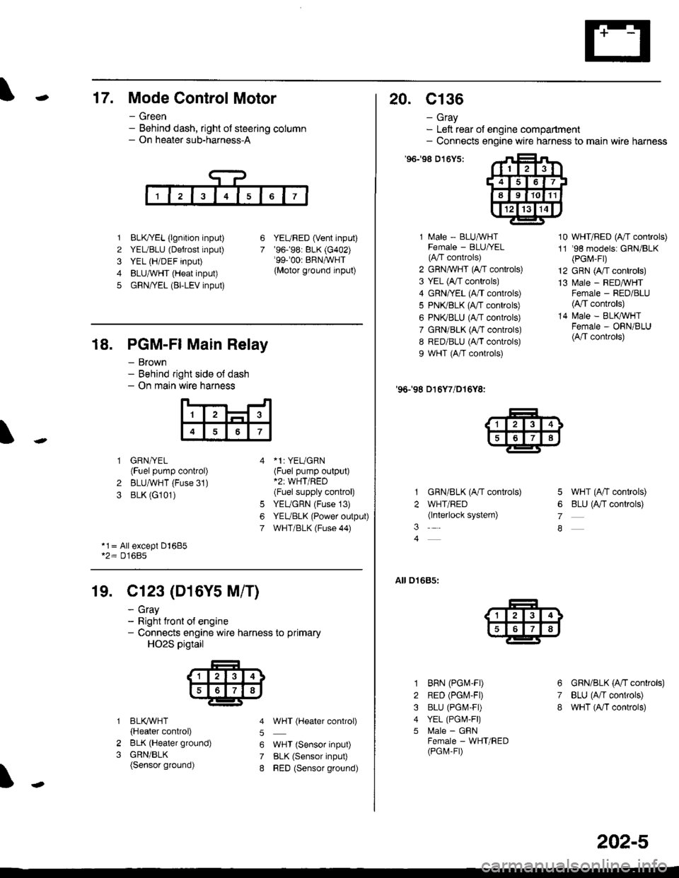
-17. Mode Control Motor
- Green- Behind dash, right of steering column- On heater sub-harness-A
1 BLK,TYEL (lgnition input)
2 YEUBLU (Detrost input)
3 YEL (H/DEF input)
4 BLUA/VHT (Heat input)
5 GRN/YEL (BI-LEV input)
YEURED (Vent input)'96.�98: BLK (G402)'99-'00r BRNAVHT
{Motor ground input)
6
7
18. PGM-FI Main Relay
- Brown- Behind right side o{ dash- On main wire harness
'l
4
1 GRN/YEL(Fuel pump control)
2 BLUAVHT (Fuse 31)
3 BLK (G101)
*1: YEUGRN(Fuel pump output)*2: WHT/RED(Fuel supply control)
YEUGRN (Fuse 13)
YEUBLK (Power output)
WHT/BLK (Fuse 44)
6
7
*1= All except Dl685*2= D16Bs
19. Cl23 (D16Y5 M/T)
2
3
BLI(WHT
{Heater control)
BLK (Heater ground)
GRN/BLK(Sensor ground)
- cray- Right tront o{ engine- Connects engine wire harness to primary
HO2S pigtail
5
6
7
8
WHT (Hgater control)
WHT (Sensor input)
BLK (Sensor input)
RED (Sensor ground)
20. c136
- Gray- Left rear of engine compartment- Connects engine wire harness to main wire harness
'96198 D't6Y5:
1 Male - BLUAVHTFemale - BLU|/EL(A"/T controls)
2 GRN,^WHT (A,/T controls)
3 YEL (A/T controls)
4 GRN/YEL (A/T controls)
5 PN(BLK (fff gs6lrq;s;
6 PNI(BLU (A/T controls)
7 GRN/BLK (Ar/T controls)
8 RED/BLU (A/T controls)
9 WHT (A/T controls)
'96198 D16Y7/D16Y8:
GRN/BLK (A/T controls)
WHT/RED(lnterlock system)
10 WHT/RED (A"/T controls)
11 '98 models: GRN/BLK(PGr,4-Fr)
12 GRN (A/T controls)
13 l\4ale - REDMHTFemale - RED/BLU(4,/T controls)
14 N4ale - BLIVWHTFemale - ORN/BLU(A/T controls)
5 WHT (A/T controls)
6 BLU (Antf se11re;s;
7
A
01685:
3
1
2
3
4
5
6
7
8
BRN (PGM-FD
RED (PGIV-FD
BLU (PGI\4-FD
YEL (PGI,4,F|)
l\4ale - GFNFemale - WHT/RED(PGM-FD
GRN/BLK (A'tl gs6trels;
BLU (A/T controls)
wHT (A/I controls)
202-5
Page 2113 of 2189
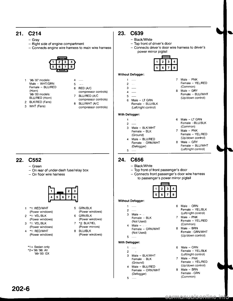
21. C214
- Gray- Right side of engine compartment- Connects engine wire harness to main wire harness
'96- 97 models:Male - WHT/GRNFemale - BLU/FED(Horn)'98-'00 models:BLU/RED (Horn)
BLKRED (Fans)
WHT (Fans)
4
5
6
7
*io t0,,"compressor controls)
BLU/RED (A,/C
compressor controls)
BLU,ryVHT (I'/C
compressor controls)
2
3
23. C639
- Black,ryVhite- Top front ot driver's door- Connects driver's door wire harness to driver's
power mirror pigtail
Without Defogger:
1
2
4
6 Male - LT GRNFema|e - BLU/BLK(Left/right control)
With Oelogger:
1
2
3 l\,lale - BLKAVHTFemale - BLK(Ground)
4 lvlale - BLU/REDFemale ORNAVHT(Delogge4
lvlale PNKFemale - YEURED(Common)
MaIe _ GRYFemale BLUA/VHT(Up/down control)
lvlale - LT GRNFemale BLU/BLK(Corrmon)
i.4ale - PNKFemale - YEURED(Up/down conkol)
Male - GRYFemale - BLU,ryVHT(Lett/right control)
22. C552
- Green- On rear of under-dash fuse/relay box- On tloor wire harness
1 *1: FEDA/VHT(Power windows)
2 *1: YEL/BLK(Power windows)
3 *1:YEL/BLK
(Power windows)
4 *1 | RED/WHT(Power windows)
*1= Sedan only*2='96''98:All'99-'00r GX
6
7
GRN/BLK(Power windows)
GRN/BLK(Power windows)*2: BLK/YEL(Power mifiors)
BLU/BLK
{Power windows)
202-6
24. C556
- Black,ryVhite- Top front of front passenger's door- Connects tront passengefs door wire harness
to passenger's power mirror pigtail
Without Defogger:
l
2
3 l\4ale -
Female BLK(Not Used)
4 l\4ale -
Female - ORN/WHT(Not Used)
With Delogger:
1
2
3 Male - BLK^VHTFemale - BLK(Ground)
4 l\.4ale - BLU/REDFemale - ORNAVHT(Defogger)
Male OBNFemale - YEUBLK(LefVright control)
l\4ale - PNKFemale - YEL/RED(Common)
Male BRNFemale - GRNA/VHT(Up/down conkol)
[.4ale - ORNFemale - YEL/BLK(Left/right control)
lrale - PNKFemale - YEURED(Up/down conkol)
l\,lale - BFNFemale'GFiN(Common)
Page 2115 of 2189
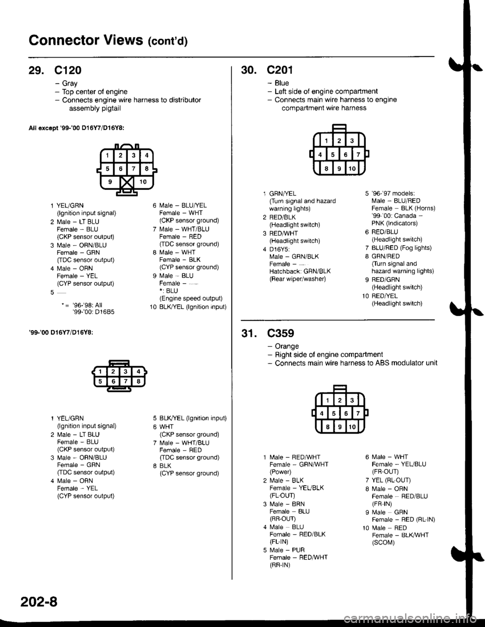
Connector Views (cont'd)
29. C120
- Gray- Top center of engine- Connects engine wire harness to distributor
assembly pigtail
All except '99-'00 016Y7/D16Y8:
l YEUGRN(lgnition input signal)
2 l\.4ale - LT BLUFemale - BLU(CKP sensor output)
3 Male - ORN/BLUFemale - GRN
[tDC sensor output)
4 l\.4ale - ORNFemale - YEL(CYP sensor output)
-= '96j98: All'99100: D1685
'99-'00 016Y7/D16Y8:
l YEUGRN(lgnition input signal)
2 Male - LT BLUFemale - BLU(CKP sensor output)
3 Male - ORN/BLUFemale - GRN
CIDC sensor output)
4 Male - ORNFemale - YEL
{CYP sensor output)
l\4ale - BLU/YELFemale - WHT(CKP sensor ground)
l\.4ale - WHT/BLUFCMAIE _ HtsL'(TDC sensor ground)
l\4ale - WHTFemale - BLK(CYP sensor ground)
Male - BLUFemale - . -*: BLU(Engine speed output)
BLK/YEL (lgnition input)
BLK/YEL (lgnition input)
WHT(CKP sensor ground)
Male - WHT/BLUFemale - RED
ffDC sensor ground)
BLK(CYP sensor ground)
10
202-8
30. c201
- Blue- Left side of engine compartment- Connects main wire harness to engine
compartment wire harness
l GRNA/EL(Turn signal and hazardwarning lights)
2 RED/BLK(Headlight switch)
3 REDAVHT(Headlight switch)
4 D16Y5:Male - GRN/BLKFemale -
Hatchbacki GRN/BLK
{Bear wipetwashe0
7
I
9b- 9/ mooets:lvlale - BLU/REDFemale BLK (Horns)'99-'00: Canada -
PNK (lndicators)
RED/BLU(Headlight switch)
BLU/RED (Fog lights)
GRN/RED
Cturn signal andhazard warning lights)
BED/GRN(Headlight switch)
RED/YEL(Headlight switch)
31. C359
- Orange- Right side ot engine compartment- Connects main wire harness to ABS modulator unit
10
l\4ale - REDAVHTFemale - GRNA/VHT(Power)
l\,4ale - BLKFemale - YEVBLK(FL-OUr)
Male - 8RNFemale BLIJ
{RR-OLrr)l\4ale BLUFemale - RED/BLK(FL-rN)
Male - PURFemale - RED&VHT(RR-rN)
6 Male - WHTFemale - YEUBLU(FR-OUr)
7 YEL (RL-OUr)
I Male - ORNFemale - RED/BLU(FR rN)
I Male GRNFemale - RED (RL-|N)
10 Male REDFemale - BLK,ryVHT(scol\,1)
Page 2117 of 2189
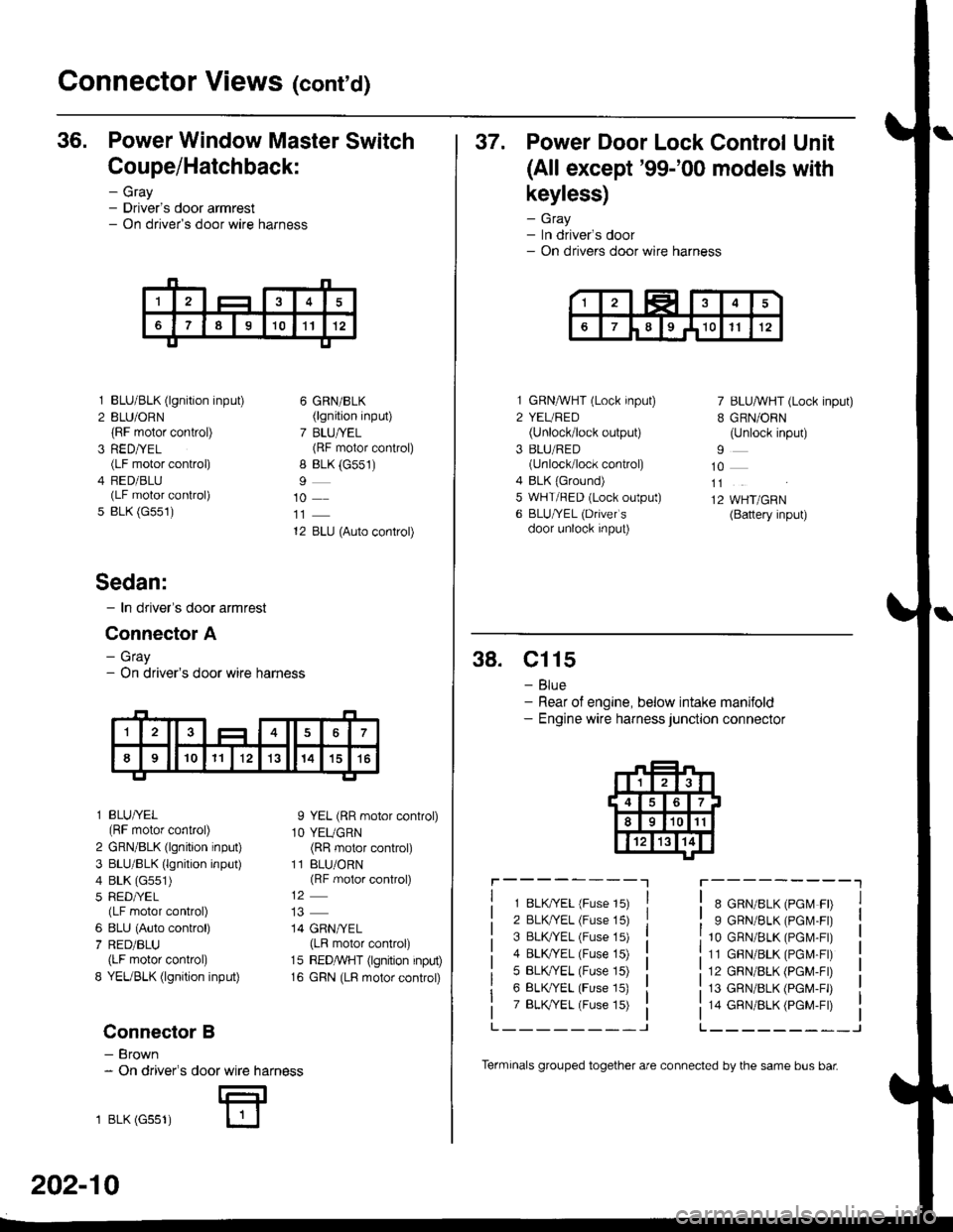
Connector Views (cont'd)
36. Power Window Master Switch
Coupe/Hatchback:
- Gray- Driver's door armrest- On driver's door wire harness
3
5
BLU/BLK (lgnition input)
BLU/ORN(RF motor control)
RED/YEL(LF motor control)
FED/BLU(LF motor control)
BLK (G551)
6 GRN/BLK(lgnition input)
7 BLU/YEL(RF motor control)
8 BLK (G551)
10
12 BLU (Auto control)
I YEL (RR motor control)
1O YEUGRN(RR motor control)
11 BLU/ORN(RF motor control)
14 GRN/YEL(LR motor control)
15 REDMHT (lgnition input)
16 GRN (LR motor control)
Sedan:
- In driver's door armrest
Connector A
- Gray- On driver's door wire harness
l BLU/YEL(RF motor control)
2 GRN/BLK (lgnition input)
3 BLU/BLK (lgnition input)
4 BLK (G551)
5 RED/YEL(LF motor control)
6 8LU (Auto control)
7 RED/BLU(LF motor control)
8 YEUBLK (lgnition input)
Connector B
- Brown- On driver's
1 BLK (Gss1)
door wire harness
E
202-10
Terminals grouped together are connected by the same bus bar
37. Power Door Lock Control Unit
(All except'99-'00 models with
keyless)
- Gray- In driver's door- On drivers door wire harness
1 GRNMHT (Lock input)
2 YEURED(Unlock/lock output)
3 BLU/RED(unlock/lock control)
4 BLK {Ground)5 WHT/RED (Lock output)
6 BLU/YEL (Drivefs
door unlock input)
7 BLU/WHT (Lock input)
B GRN/ORN(Unlock input)
10
11
12 WHT/GRN(Battery input)
38. Cl15
- Blue- Rear of engine, below intake manifold- Engine wire harness junction connector
r----------lr---------"1
1 8LK?ryEL (Fuse 15)
2 BLK/YEL (Fuse 15)
3 BLK TEL (Fuse 15)
4 BLK/YEL (Fuse 15)
5 BLK,/YEL (Fuse 15)
6 BLK/YEL (Fuse 15)
7 BLK,TYEL (Fuse 15)
8 GRN/8LK (PGM FD
9 GRN/BLK (PGM.FD
10 GRN/BLK (PGr\,4-Fr)
11 GBN/BLK (PGM-Fr)
12 GRN/BLK (PGM-FD
13 GRN/BLK (PGM-FD
14 GRN/BLK (PGM-Fr)
L_______-JL______--_J
Page 2141 of 2189
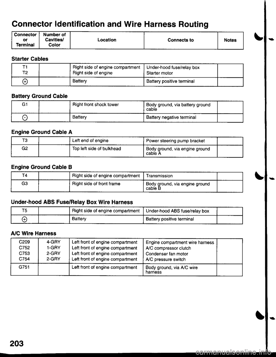
Connector ldentification and Wire Harness Routing
Connector
or
Terminal
Number of
Cavities/
Color
LocationConnects toNotes
Starter Cables
T1
r2
Right side of engine compartment
Right side of engine
Under-hood luse/relay box
Staner motor
t+lBatteryBattery positive terminal
Battery Ground Cable
Right front shock towerBody ground, via battery ground
cable
oBatteryBattery negative terminal
Engine Ground Cable A
t!tLeft end of enginePower steering pump bracket
Too left side ot bulkheadBody ground, via engine ground
cable A
Engine Ground Cable B
T4Bight side of engine compartmentTransmission
(ritRight side of front frameBody ground, via engine ground
Under-hood ABS Fuse/Relay Box Wire Harness
tcRight side of engine compartmentUnder-hood ABS fuse/relay box
oBatteryBattery positive terminal
A,/C Wire Harness
c209
wtJl/,\-7Ee
c754
4-GRY
1.GRY
2-GRY
2-GRY
Lefl front of engine compartment
Left front of engine compartment
Lefl front of engine compartment
Left tront of engine compartment
Engine compartment wire harness
A,/C compressor clutch
Condenser fan motor
A,/C pressure switch
G751Left front of engine compartmentBody ground, via A,/C wireharness
Page 2142 of 2189
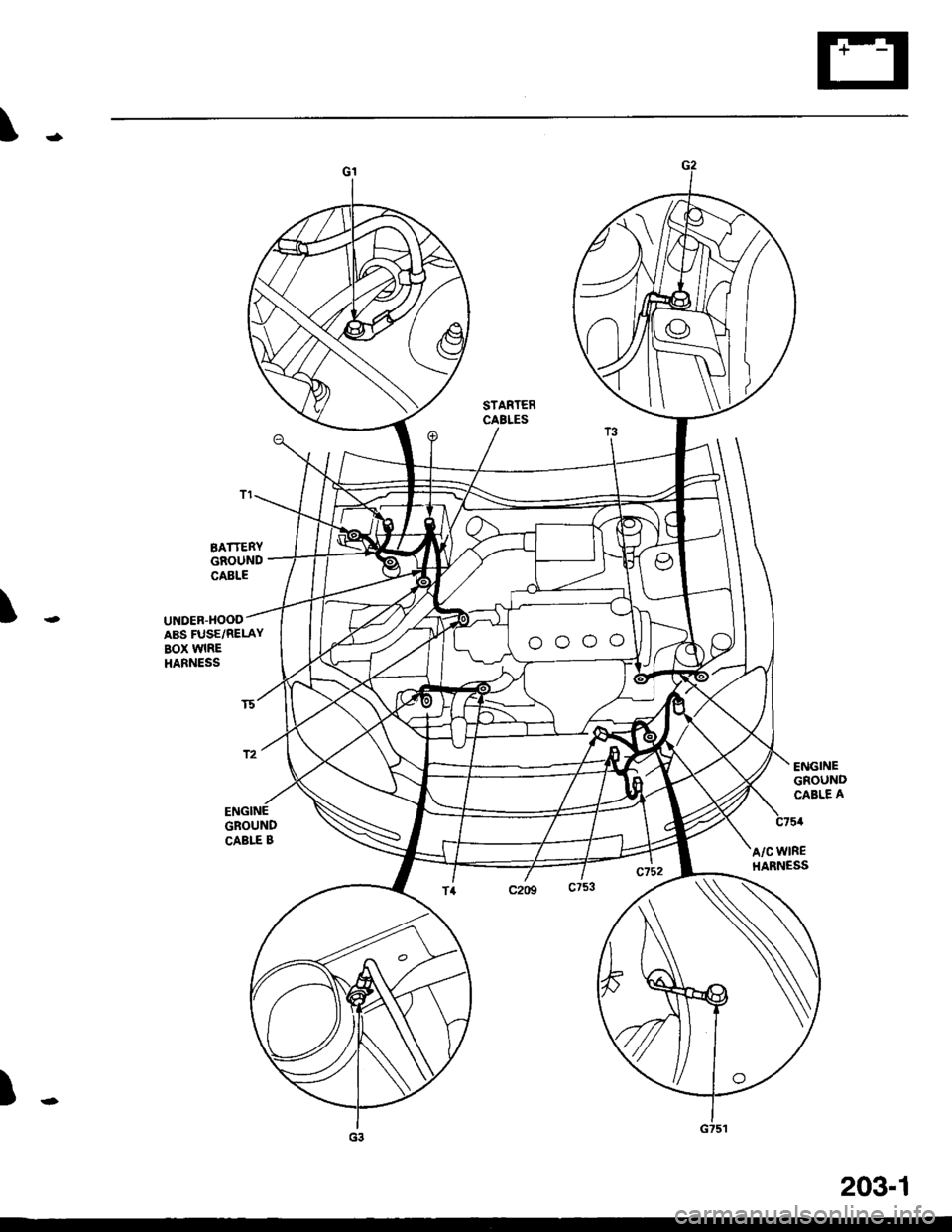
\..
STARTERCABLES
\..UNDER.HOODABS FUSE/RELAYBOX WIREHARNESS
BATTERYGROUNDcAELE
ENGINEGROUNDCAELE BA/C WIREHARNESS
)-
203-1