Connector a HONDA CIVIC 1996 6.G Workshop Manual
[x] Cancel search | Manufacturer: HONDA, Model Year: 1996, Model line: CIVIC, Model: HONDA CIVIC 1996 6.GPages: 2189, PDF Size: 69.39 MB
Page 489 of 2189
ldle Control System
ldle Speed Setting
Inspection/Adiustmenl
'96, '97 Dl6Y5. '96 - 00 Dl5Y8 sngine with M/T
NOTE:
. Before setting the idle speed, check the following
items:- The MIL has not been reported on.- lgnition timing- Spark plugs- Air cleaner- PCV system
o (Canada) Pull the parking brake lever up. Start the
engine, then check that the headlights are off.
1. Start the engine. Hold the engine at 3.000 rpm withno load (taansmission in neutral) until the radiatorfan comes on, then let it idle.
2. Connect a tachometer.
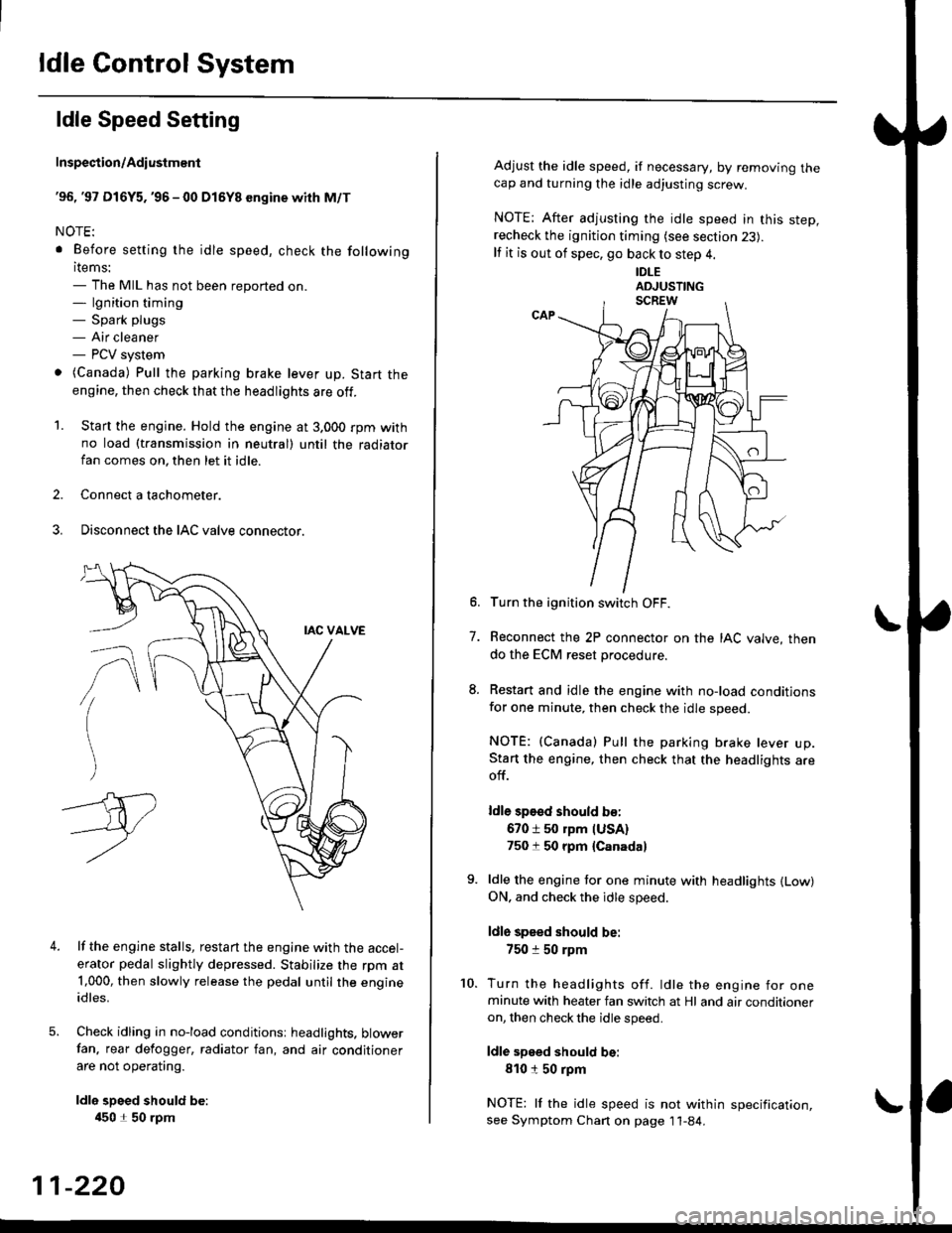
3. Disconnect the IAC valve connector.
4.lf the engine stalls, restart the engine with the accel-
erator pedal slightly depressed. Stabilize the rpm at1,000, then slowly release the pedal until the engineidles.
Check idling in no-load conditionsr headlights. blowerfan. rear defogger, radiator fan, and air conditioner
are not operating.
ldle spsed should be:
450 1 50 rpm
11-220
Adjust the idle speed, if necessary, by removing thecap and turning the idle adjusting screw.
NOTE; After adjusting the idle speed in this step,recheck the ignition timing (see section 23).
lf it is out of spec, go back to step 4.
IDLE
6. Turn the ignition switch OFF.
7. Reconnect the 2P connector on the IAC valve, then
do the ECM reset procedure.
8. Restart and idle the engine with no-load conditionsfor one minute, then check the idle speed.
NOTE: (Canada) Pull the parking brake lever up.Start the engine, then check that the headlights areoff.
ldle sp€sd should b€:
670 i 50 rpm IUSA)750 t 50 rpm {Canada}
9. ldle the engine tor one minute with headlights {Low)ON. and check the idle speed.
ldle speed should be:
750 :r 50 rpm
10. Turn the headlights off. ldle the engine for oneminute with heater fan switch at Hl and air conditioneron, then check the idle speed.
ldle speed should be:
810150 rpm
NOTE: lf the idle speed is not within specification,see Symptom Chan on page 11-84.
Page 490 of 2189
t
t
I
'96.'97 D16Y5 engine with CVT,'96 - 00 D16Y8 ongins
with A/T and'96 - 00 Dl6Y7 €ngine
Adiust the idle speed using a Honda PGM Tester if pos-
sible. lf not, use the following procedure:
NOTEI
. Leave the IAC valve connected
. Betore setting the idle speed. check the following
items:- The MIL has not been reported on'
- lgnition timing
- Spark Plugs- Air cleaner- PCV system
1. Connect a tachometer.
2. Start the engine. Hold the engine at 3,000 rpm wirh
no load (in Park or neutral) until the radiator fan
comes on, then let it idle.
3. Check the idle speed with no-load conditions: head-
iights, blower fan, rear defogger, radiator fan, and
air conditioner are not operatlng
ldl€ spoed should be:
USA:
D16Y5 engine with CVT, D16Y7 engine with A/T'
Dl6YB engine with A/T:
700 :r 50 rpm (in E or El Positionl
D16Y7 engine with M/T:
670 i 50 rpm
Canada:
Dl6Y8 sngin€, Dl6Y7 engins:
M/T750 t 50 rpm
NT750 1 50 rpm (in E or El Position)
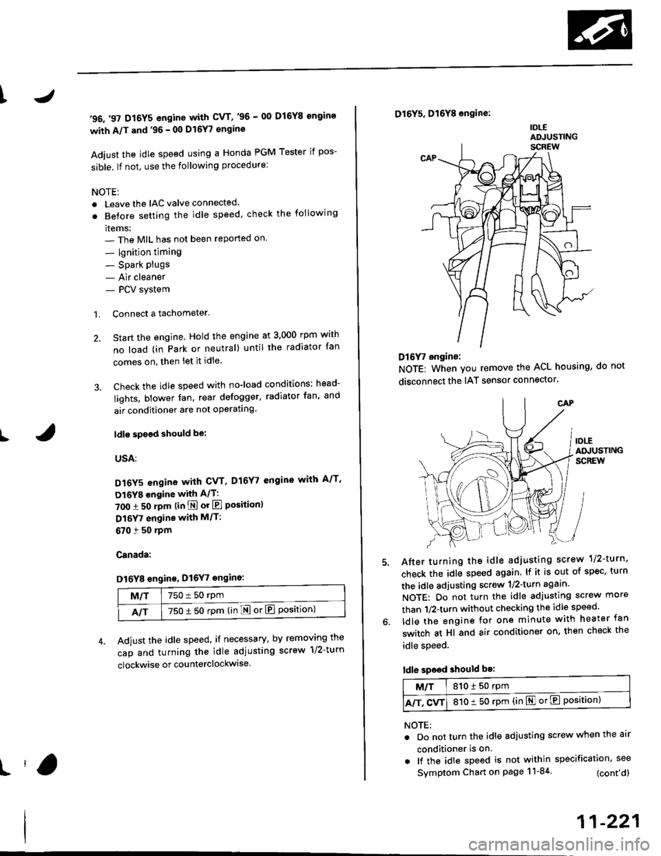
Adjust the idle speed, if necessary, by removing the
cap and turning the idle adiusting screw 1/2-turn
clockwise or counterclockwise
D16Y5, D16Y8 engine:
IDLEADJUSTING
Dl6f, ongine:
NOTE: When you remove the ACL housing, do not
disconnect the IAT sensor connector
After turning the idle adjusting scrow 1/2-turn'
check the idle speed again. lf it is out of spec, turn
the idle adjusting screw 1/2-turn agaan'
NOTE: Do not turn the idle adjusting screw more
than 1/2-turn without checking the idle speed'
ldle the engine for one minute with heater fan
switch at Hl and air conditioner on, then check the
idle speed.
ldle speed should be:
M/T810150 rpm
A/T. CvT810 t 50 rpm (in El or E Position)
NOTE:
. Do not turn the idle adjusting screw when the air
conditioner is on.
. lf the idle speed is not within specification. see
Symptom Chart on page 11-84 (cont'd)
11-221
Page 491 of 2189
ldle Control System
ldle Speed Setting (cont'dl
Inspeqtion/Adiustment
38 D16Y5 engine whh M/T,'99 - 00 81642 engine
NOTE: Before setting the idle speed, check the follow-ing items;- The MIL has not been reported on.- lgnition timing- Spark plugs- Air cleaner- PCV system
'1. Start the engine. Hold the engine at 3,000 rpm withno load (transmission in neutral) until the radiatorfan comes on, then let it idle.
Connect a tachometer.
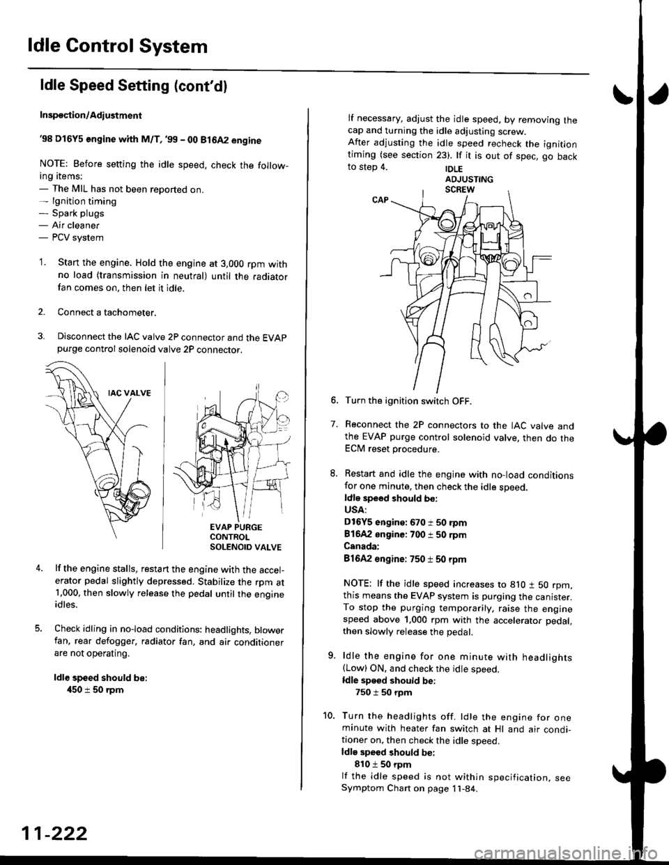
Disconnect the IAC valve 2P connector and the EVAPpurge controlsolenoid valve 2P connector.
EVAP PURGECONTROLSOLENOID VALVE
lf the engine stalls, restart the engine with the accel-erator pedal slightly depressed. Stabilize the rpm at1.000, then slowly release the pedal until the engineidles.
Check idling in no-load conditions: headlights, blowerfan, rear defogger, radiator fan, and air conditionerare not operating.
ldl€ speed should be:
450 i 50 rpm
11-222
lf necessary, adjust the idle speed, by removrng lnecap and turning the idle adjusting screw.After adjusting the idle speed recheck the ignitlontiming (see section 23). lf it is out of spec, go backto step 4. |DLE
6. Turn the ignition switch OFF.
7. Reconnect the 2P connectors to the IAC valve andthe EVAP purge control solenoid valve, then do theECM reset procedure.
8. Restart and idle the engine with no-load conditionsfor one minute, then check the idle sDeed.ldle speed should bo:
USA:
D16Y5 engine: 670 i 50 rpm
81642 engine: 700 i 50 rpm
Canada:
81642 engine: 750 t 50 rpm
NOTE: lf the idle speed increases to 8lO t 50 rpm,this means the EVAP system is purging the canister.To stop the purging temporarily, raise the enginespeed above 1,000 rpm with the accelerator pedal,
then slowly release the pedal.
9. ldle the engine for one minute with headlights(Low) ON. and check the idle speed.
ldle speed should be:
750 i 50 rpm
10. Turn the headlights off. ldle the engine for oneminute with heater fan switch at Hl and air condi-tioner on, then check the idle soeed.ldls speed should be:
810 t 50 rpm
lf the idle speed is not within specification, seeSymptom Chart on page 11-84.
Page 492 of 2189
\
I
'98 - 0O D16Y5 ongine with CvT
Adjust the idle speed using a Honda PGM Tester if pos-
sible. lf not, use the following procedure:
NOTE:
. Leave the IAC valve connected.
. Before s€tting the idle speed, check the following
rtems:- The MIL has not been reported on.
- lgnition timing
- Spark Plugs- Air clean€r
- PCV svstem
'1. Connect a tachometer.
2. Stan the engine. Hold the engine at 3,000 rpm w'th
no load (transmission in E or E] position) until the
radiator Jan comes on, then let it idle.
3. Check the idle speed under no-load conditions:
head lights, blower fan, rear defogger, radiator fan,
and air conditioner are not operatlng.
ldlo spaod ehould bo: 700 t 50 rpm
. lf the idle speed is within the specification, the
procedure is comPlete.
. lf the idle sDeed is out of specitication, 9o to step 4'
4. tf the idle speed is 810 1 50 rpm, this means the
EVAP system is purging the canister. To stop the
purging temporarily, raise the engine speed above
l,OO0 rgm with the accelsrator pedal. Slowly release
the pedal. and rscheck the idl€ speed.
. tf the idle speed is within the specificstion, the
Drocedure is comPlete.
. lf the idle sp€ed is out of spocification, go to step 5.
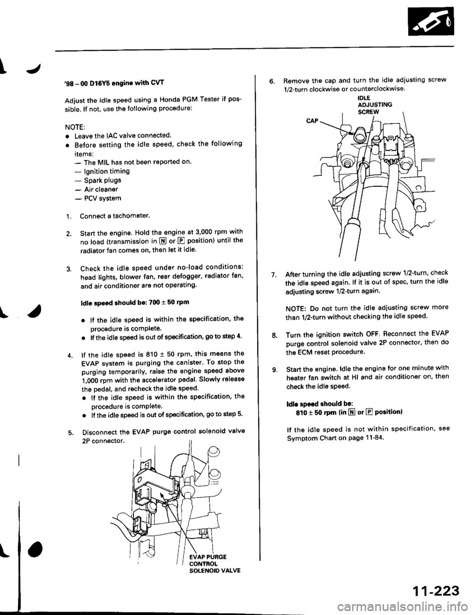
5. Disconnect th€ EVAP purgs control solenoid valve
2P connector.
EVAP PURGECONTROL
6. Remove the cap and turn the idle adiusting screw
1/2-turn clockwise or counterclockwlse
IDLE
7.After turning the idle adjusting screw 1/2-turn, check
the idl€ speed again. lf it is out of spec, turn the idle
adjusting screw 1/2-turn again.
NOTE: Do not turn the idle adjusting screw more
than 1/2-turn without checking the idle speed.
Turn the ignition switch OFF. Reconnect the EVAP
purge control solenoid valve 2P connector' then do
the ECM reset Procedure.
Start the engine. ldle the engine for one minute with
heater fan switch at Hl and air conditioner on, then
check the idle speed.
ldle spaed should be:
810 t 50 rpm (in El or E Posiiion)
lf the idle speed is not within specification, see
Svmptom Chart on Page 11-84.
9.
SOLENOID VALVE
11-223
Page 496 of 2189
I
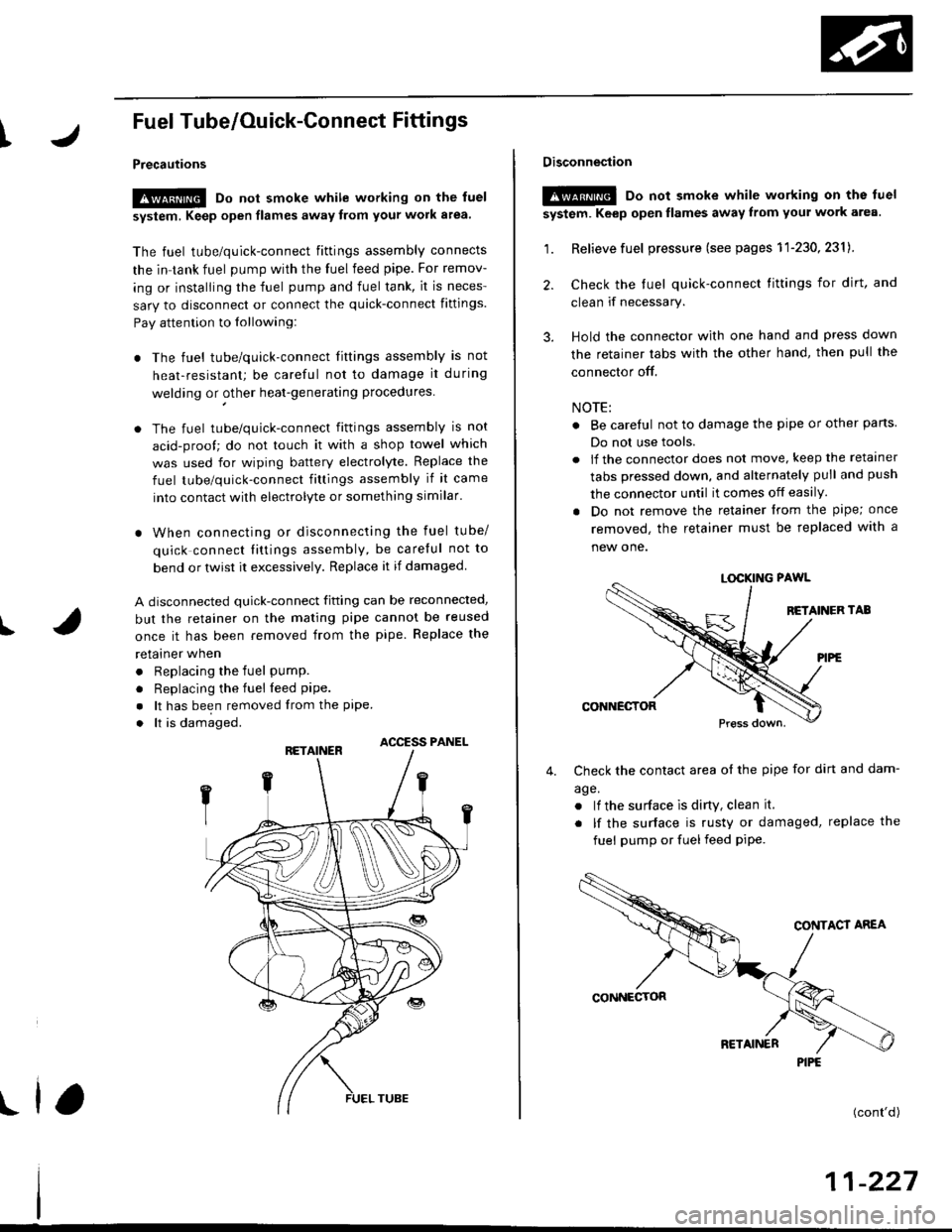
Fuel Tube/Ouick-Gonnect Fittings
Precautions
!@ Do not smoke while working on the fuel
system, Keep open flames away from your work a.ea'
The fuel tube/quick-connect fittings assembly connects
the in tank fuel pump with the fuel feed pipe. For remov-
ing or installing the fuel pump and fuel tank, it is neces-
sary to disconnect or connect the quick-connect fittings.
Pay attention to lollowing:
. The fuel tube/quick-connect fittings assembly is not
heat-resistant; be careful not to damage it during
welding or other heat-generating procedures
. The fuel tube/quick-connect fittings assembly is not
acid-proof; do not touch it with a shop towel which
was used for wiping battery electrolyte. Replace the
fuel tube/quick-connect fitlings assembly if it came
into contact with electrolyte or something similar.
. When connecting or disconnecting the fuel tube/
quick connect liltings assembly, be careful not to
bend or twist it excessively. Replace it if damaged
A disconnected quick-connect fitting can be reconnecled,
but the retainer on the mating pipe cannot be reused
once it has been removed from the pipe. Replace the
retatner wnen
. Replacing the fuel pump.
. Replacing the fuel leed pipe.
. lt has been removed lrom the PiPe.. lt is damaged.
ACCESS PANEL
I
Disconnestion
!@ Do not smoke while working on the luel
system. Keep open llames away lrom youl work area.
1. Relieve fuel pressure (see pages 11'230,2311.
2. Check the tuel quick-connect tittings for dirt, and
clean if necessary.
3. Hold the connector with one hand and press down
the retainer tabs with the other hand, then pull the
connector off.
NOTE:
o Be carelul not to damage the pipe or other pans
Do not use tools.
. lf the connector does not move, keep the retainer
tabs pressed down, and alternately pull and push
the connector until it comes off easily.
. Do not remove the retainer from the pape; once
removed, the retainer must be replaced with a
new one.
LOCKING PAWL
BETAINER TAB
CONNECTOR
Check the contact area o{ the pipe for dirt and dam-
age.
. lf the surface ls dirty, clean it.
. lf the surface is rusty or damaged, replace the
fuel pump or fuel feed piPe.
4.
(cont'd)
11-227
PIPE
Page 497 of 2189
Fuel Supply System
Fuel Tube/Ouick-Connect Fittings (cont'd)
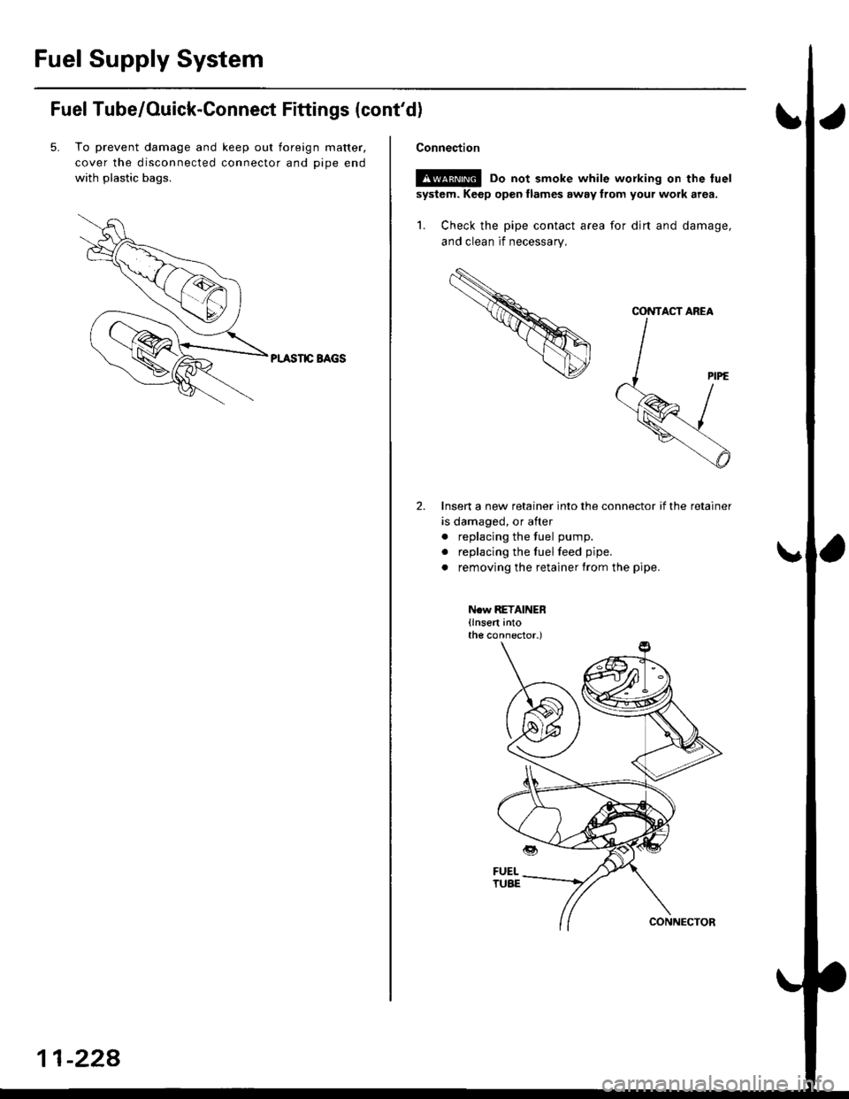
5. To prevent damage and keep out toreign matter,
cover the disconnected connector and oioe end
with plastic bags.
PI.ASIIC BAGS
11-228
Connection
!s@ Do not smoke while working on the fuel
system. Keep open llames away from your work area.
1. Check the pipe contact area for djrt and damage,
and clean if necessary,
Insert a new retainer into the connector if the retainer
is damaged, or after
. replacing the fuel pump.
. replacing the fuelfeed pipe.
. removing the retainer from the pipe.
N.w RETAINER(lnsert intothe connector.)
CONTACT AREA
Page 498 of 2189
t
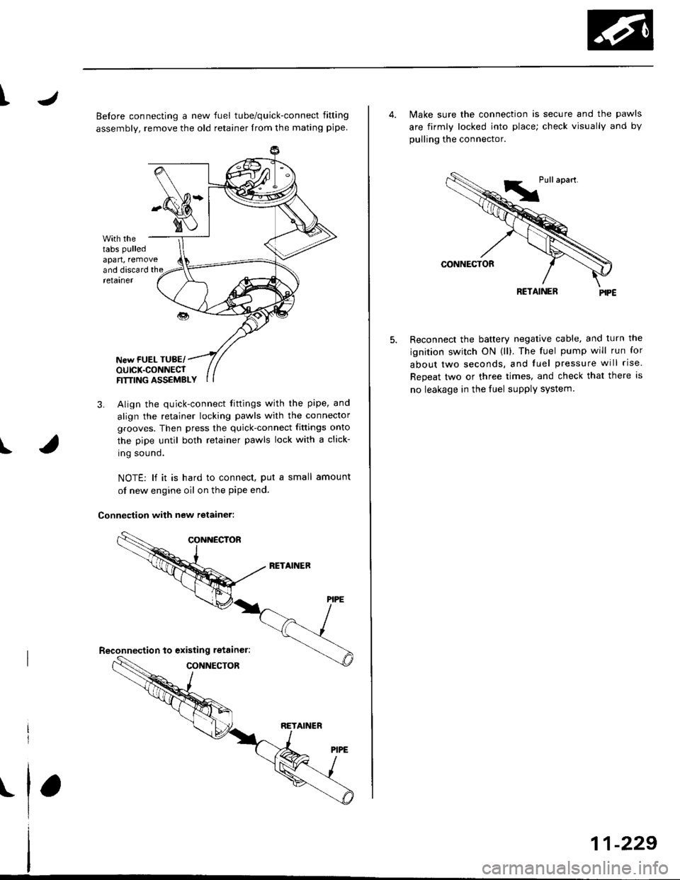
Belore connecting a new fuel tube/quick-connect fining
assembly, remove the old retainer from the mating pipe
with thetabs pulled
apan, removeand discard the
I
retarner
New FUEL TUBE/OUICK.CONNECTFITTING ASSEMELY
3. Align the quick-connect fiftings with the pipe, and
align the retainer locking pawls with the connector
grooves. Then press the quick-connect fittings onto
the pipe until both retainer pawls lock with a click-
ing sound.
NOTE: lf it is hard to connect, put a small amount
of new engine oil on the pipe end.
Connection with new retainer:
4. Make sure the connection is secure and the pawls
are firmly locked into place; check visually and by
pulling the connector.
RCTAINER
Reconnect the battery negative cable, and turn the
ignition switch ON (ll). The fuel pump will run for
about two seconds, and fuel pressure will rise.
Repeat two or three times, and check that there is
no leakage in the fuel supplv system
11-229
Page 501 of 2189
Fuel Supply System
Fuel Injectors
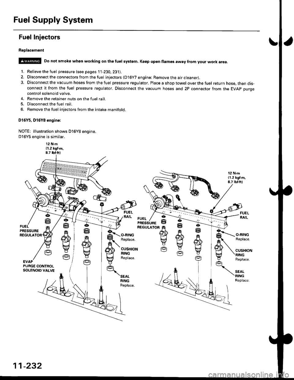
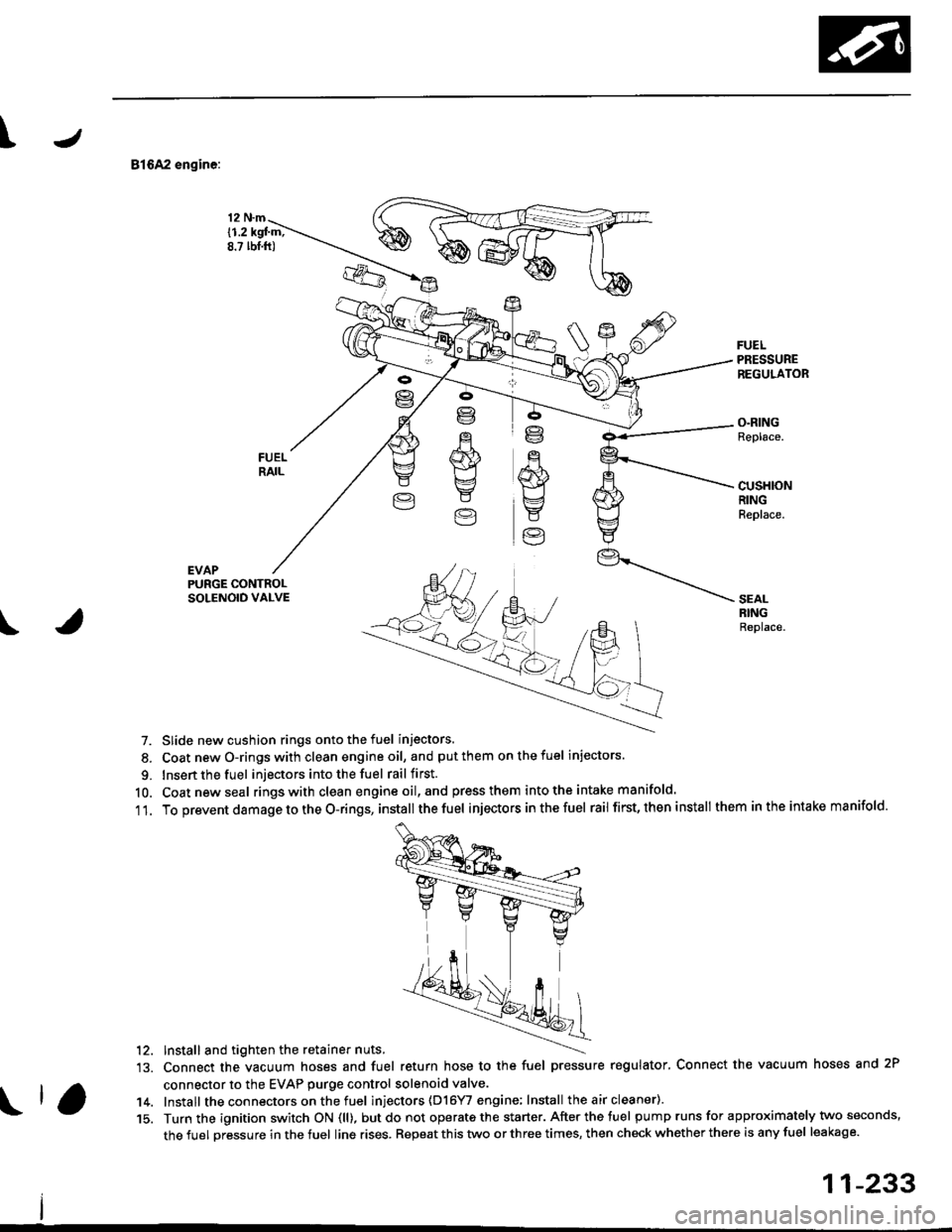
Replacement
@ Do not smoke when working on the tuel systgm, Keep gp6n flames away from your work area
'f. Relieve the fuel pressure (see pages 11-230,231J.
2. Disconnect the connectors from thefuel injectors (D16Y7 engine: Remove the air cleaner).
3. Disconnect the vacuum hoses from thefuel pressure regulator. Placeashoptowel overthefuel return hose, then dis-connect it from the fuel pressure regulator. Disconnect the vacuum hoses and 2P connector from the EVAp purgecontrol solenoid valve.
4. Remove the retainer nuts on the fuel rail.
5. Disconnect the fuel rail.
6. Removethefuel injectors from the intake manifold.
D16Y5, D16Y8 engine:
NOTE: lllustration shows D16Y8 engine.
D16Y5 engine is similar.
12 N.m11.2 kgl.m,8.7 rbt.ft)
12 N.m11.2 lgl.m,8.7 rbt.ftl
.q
wE4
Y
Ve
ffi}Yg
E
O.RINGReplace.
CUSHIONRINGReplace.
O.RINGReplace.
cusl{toNRINGReplace.
SEALRINGReplace.
ffi
E
EV
R
w
t
YEVAPPURGE CONTNOLSOLENOID VALVE
FUEL
11-232
Page 502 of 2189
\J
81642 engine:
EVAP
12 N.m
{1.2 kgl m;8.? lbt.ft)
FUELPRESSUREREGULATOR
O.RINGReplace.
cusHloNRINGReplace.
PURGE CONTROLSOLENOID VALVE
\
SEALRINGReplace.
7. Slide new cushion rings onto the fuel injectors.
8. Coat newO-ringswith clean engineoil, and putthem onthefuel injectors.
9. Insert the fuel injectors into the fuel rail first.
10. Coatnewseal rings with clean engine oil,and press them intothe intake manifold.
11. To prevent damage to the O-rings, installthe fuel injectors inthefuel rail first, then install them inthe intake manifold.
'12. Install and tighten the retainer nuts.
13. Connect the vacuum hoses and fuel return hose to the fuel pressure regulator, Connect the vacuum hoses and 2P
connector to the EVAP purge control solenoid valve.
14. Install the connectors on the fuel inl'ectors (D16YI engine; Install the air cleaner).
15. Turn the ignition switch ON (ll), butdo not operate the starter. After the tuel pump runs for approximately two seconds,
the fuel pressure in the fuel line rises. Repeat this two or three times, then check whether there is any fuel leakage.
11-233
Page 505 of 2189
Fuel Supply System
Fuel Pump
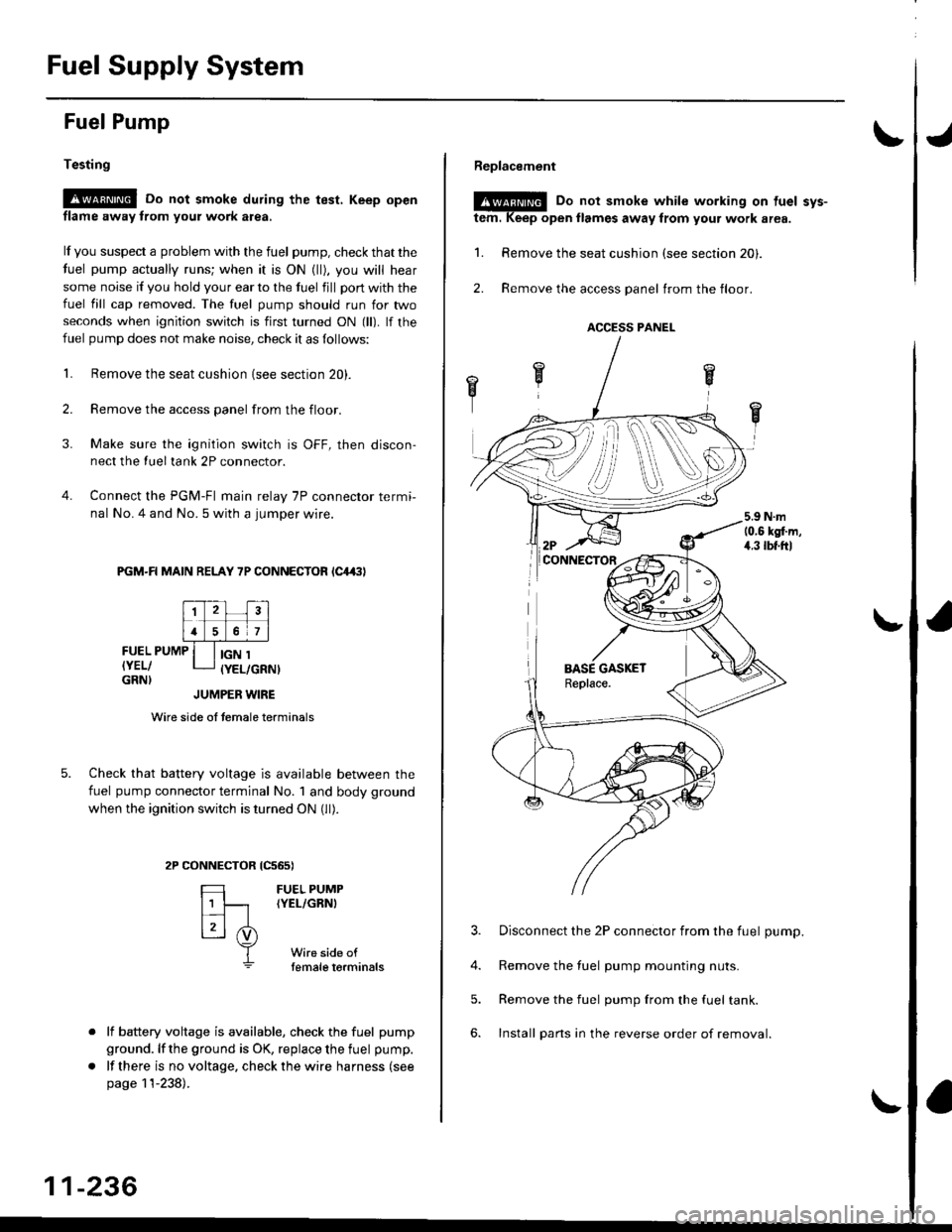
Testing
!@ Do not smoke during the test, Keep open
flame away from your work atea,
lf you suspect a problem with the fuel pump, check that the
fuel pump actually runs; when it is ON (ll), you will hear
some noise if you hold your ear to the fuel fill port with the
fuel fill cap removed. The fuel pump should run for two
seconds when ignition switch is first turned ON (ll). lf the
fuel pump does not make noise, check it as follows:
L Remove the seat cushion {see section 20).
2. Remove the access panel from the floor.
3. Make sure the ignition switch is OFF, then discon-
nect the Iueltank 2P connector.
4. Connect the PGM-FI main relay 7P connector termi-
nal No. 4 and No. 5 with a jumper wire.
PGM-R MAIN RELAY 7P CONNECTOR lC4,(|l
FUEL PUMP
IYEL/GRN}
IGN 1(YEL/GRNI
tcs6s)
FUEL PUMP(YEL/GRNI
Wire side oftemale torminals
JUMPER WIRE
Wire side of temale terminals
Check that battery voltage is available between the
fuel pump connector terminal No. 1 and body ground
when the ignition switch is turned ON (ll).
CONNECTOR
=
[t
L3l .i)
T
lf battery voltage is available, check the fuel pump
ground. lf the ground is OK, replace the fuel pump.
lf there is no voltage, check the wire harness (see
page 11-238).
11-236
Replacement
@E Do not smoke while working on tuel svs-
tem. Keep open llames away from your work area.
1. Remove the seat cushion (see section 20).
2. Remove the access panel trom the floor.
3. Disconnect the 2P connector from the fuel pump.
4. Remove the fuel pump mounting nuts.
5. Remove the fuel pump from the fuel tank.
6. Install pans in the reverse order of removal.
ACCESS PANEL
i