engine wire HONDA CIVIC 1996 6.G Workshop Manual
[x] Cancel search | Manufacturer: HONDA, Model Year: 1996, Model line: CIVIC, Model: HONDA CIVIC 1996 6.GPages: 2189, PDF Size: 69.39 MB
Page 1586 of 2189
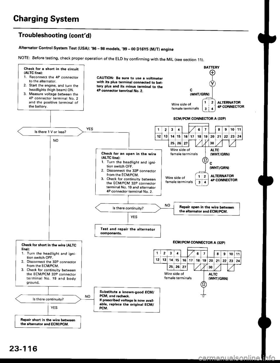
Charging System
Troubleshooting (cont'd)
Alternator Control System Test (USA): ,96 - 98 modets, ,99 _ 00 Dl6y5 (M/Tl engine
NorE: Before testing. check proper operation of the ELD by confirming with the MrL {see section r 1).
BATTERY
CAUTION: Be 3ure to use a voltmot€.with its plus terminal connected to b.t-tery plus and its minus terminal to the{P connectoi tgmrinal No. 2.c
{WHT/GRNt
Wire side oIfemale terminals
ALTERNATOR.P CONNECTOB
Check for a 3hort in the circuitIALTC linel:1. Reconnect the 4P connectorto the alternator,2. Stan the engine, and turn theheadlights {high beam) ON.3. Measure voltage between the4P connector terminal No. 2and the positive terminal ofthe battery.
ls there 1V or less?
Check for rn opon in tha wire(ALTC linol:1. Turn the headlight and igni-tion switch OFF.2. Disconnect the 32P connectortrom the ECM/PCN4.3. Check tor continuity betweenthe ECM/PCM 32P connectorterminal No. 19 and alternator4P connector terminal No. 2.
Bspair open in thg wire lrstweenthe rhern.tor .nd ECM/PCM.
Check for short in the wire (ALTClinel:1. Turn the headlight and ignition switch OFF.2. Disconnect the 32P connectortrom the ECM/PCM.3. Check tor continuity betweenthe ECM/PCM 32P connectorterminal No. 19 and bodyground.
Subslitute a known-good ECM/PCM, .nd .och6ck.It p.escribod vohago i! now avail-able, replace the original ECM/PCM.
Ropair 3hort in the wiro betweonthe ahe.nator and ECM/PCM.
ECM/PCM CONNECTOR A I32PI
'Ia18I1011
121314151718t9
7
202'l2221
262730
Wire side offemale terminalsALTC(WHT/GRNI
c{WHT/GRNI
ALTERNATORWire side oIfemale terminals
([l
T
12
1
ECM/PCM CONNECTOB A (32PI
I23478910t1
1213 14151617182021222321
262730
Wire side of I AITCfemate terminats
A
(WHT/GRN|
23-116
Page 1587 of 2189
-
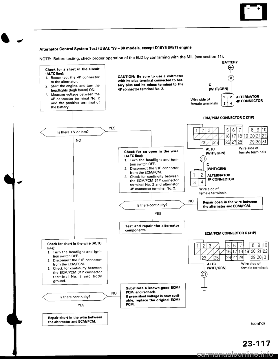
Alternator Control System Test {USA}: '99 - 0O models, except Dl6Y5 {M/T} engine
NOTE: Before testing, check proper operation ofthe ELD by confirming with the MIL (see section 11)'
BATTERY
CAUTION: Be sura lo use a voltmeter
with its plus te.minal conneqted io bat-
tery plus and it3 minus tgrminal to ths
4P connoctot tomrinal No. 2.
Wire side of
female terminals
c(WHT/GRNI
wire side offemale terminals
ALTERNATOR.P CONNECTOR
ECM/PCM CONNECTOR C 13lPI
ECM/PCM CONNECTOR C (31PI
(cont'd)
23-117
Check lor a sho.t in the circuit
{ALTC line):1, Beconnect the 4P connector
to the alternator.
2. Start the engine, and turn the
headlights (high beam) ON.
3. Measure voltage between the
4P connector terminal No. 2
and the Positive terminal of
the battery.
ls there 1 V or less?
Chcck for rn opon in the wire(ALTC lin6l:1. Turn the headlight and igni-
tion switch OFF
2. Disconnect the 31P connector
trom the ECM/PCM.
3. Check for continuity betlveen
the ECM/PCM 31P connectorterminal No. 2 and alternator
4P connector terminal No. 2
Repair opcn in the wire botweon
the alternstoi.nd ECM/PCM.ls there continuity?
Check tor short in the wire IALTC
line):1. Turn the headlight and igni-
tion switch OFF2. Disconnect the 31P connector
from the ECM/PCM.
3. Check for continuity between
the ECM/PCM 31P connector
terminal No. 2 and body
ground.
Substitute a known'good ECM/
PCM, and recheck.It prscribed voltagg is now avail'
abl€, replace tho original ECM/
PCM.
Raoair short in the wite between
the alle.nator and ECM/PCM,
1235618I10
/11611lo191 zo2122
23252621?82930JI
ALTC Wire side of(WHT/GRN) female terminals
o
Page 1610 of 2189
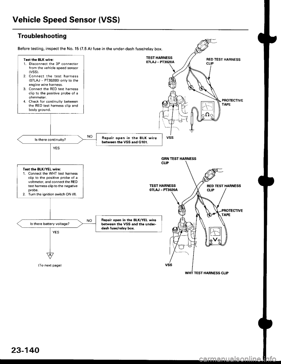
Vehicle Speed Sensor (VSSI
Troubleshooting
Before testing, inspect the No. 15 (7.5 A) fuse in the under-dash fuse/relay box.
TEST HARNESSOTLAJ _ PT3O2OAREO TEST HARNESSCLIP
PROTECTIVETAPE
TEST HARNESSOTLA' . PT3O2OA
(To next page)
Test the BLK wire:1. Disconnect the 3P connectorfrom the vehicle speed sensor(vss).
2. Connect the test harness(07LAJ PT30200) only to theengine wire harness,3. Connect the RED test harnessclip to the positive probe of a
4. Check for continuity betweenthe RED test harness clip andbody ground.
Repair opon in the BLK wireb€twe€n the VSS and G101.ls there continuity?
Te3t the BLK/YEL wire:1. Connect the WHT test harnessclip to the positive probe of avoltmeter, and connectthe REDtest harness clip to the negativeprobe.2. Turn the ignition switch ON {ll).
Repair open in iho BLK/YEL wirebetween the VSS and the under-d6sh tuse/relav box.
vss
GRN TEST HARNESS
RED TEST HARNESS
WHT TEST HARNESS CLIP
23-140
Page 1753 of 2189
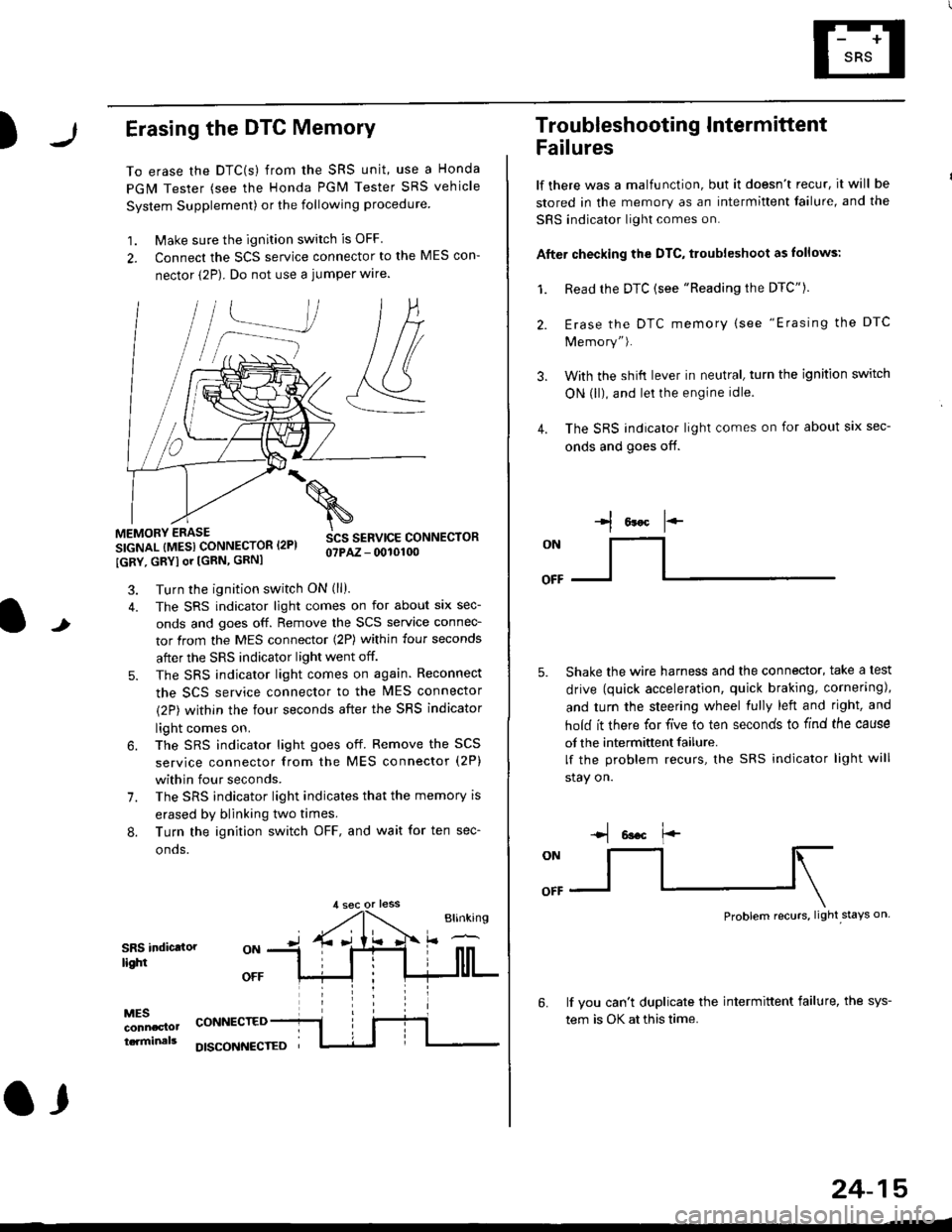
)Erasing the DTC Memory
To erase the DTC(s) from the SRS unit, use a Honda
PGM Tester (see the Honda PGM Tester SRS vehicle
System Supplement) or the following procedure
1. Make sure the ignition switch is OFF
2. Connect the SCS service connector to the MES con-
nector (2P). Do not use a jumper wlre.
]P,
&
.!--J
MEMORY ERASE
SIGNAL (MESI CONNECTOR I2PI
IGRY, GRYI or [GRN, GRNI
SCS SERVICE CONNECTORo?PAZ - 0010100
t
7.
Turn the ignition switch ON (ll).
The SRS indicator light comes on for about six sec-
onds and goes off. Remove the SCS service connec-
tor from the MES connector (2P) within four seconds
after the SRS indicator light went off.
The SRS indicator light comes on again. Reconnect
the SCS service connector to the lvlES connector
(2P) within the four seconds after the SRS indicator
light comes on.
The SRS indicator light goes off. Remove the SCS
service connector from the MES connector (2P)
within four seconds.
The SRS indicator light indicates that the memory is
erased by blinking two times.
Turn the ignition switch OFF, and wait for ten sec-
onos.
8.
SRS indictlorlighi
MESconncclottcaminals
CONNECTED
O,
DISCONI{ECTED
24-15
Troubleshooting Intermittent
Failures
lf there was a malfunction, but it doesn't recur, it will be
stored in the memory as an intermittent failure, and the
SRS indicator light comes on.
Afte. checking the DTC, troubleshoot as lollows:
1. Read rhe DTC {see "Reading the DTC"}.
Erase the DTC memory (see "Erasing the DTC
Memory").
With the shifi lever in neutral, turn the ignition switch
ON (ll), and lei the engine idle.
The SRS indicator light comes on for about six sec-
onds and goes off.
l*F
ON
tl-- -l
Shake the wire harness and the connector, take a test
drive (quick acceleration, quick braking, cornering),
and turn the steering wheel fully left and right, and
hold it there for five lo ten seconds to find the cause
of the intermittent failure.
lf the problem recurs, the SRS indicator light will
stay on.
-q 6a.c f'-
:q
Problem recurs, light stays on
3.
4.
6.lf vou can't duplicate the intermittent failure, the sys-
tem is OK at this time.
Page 1824 of 2189
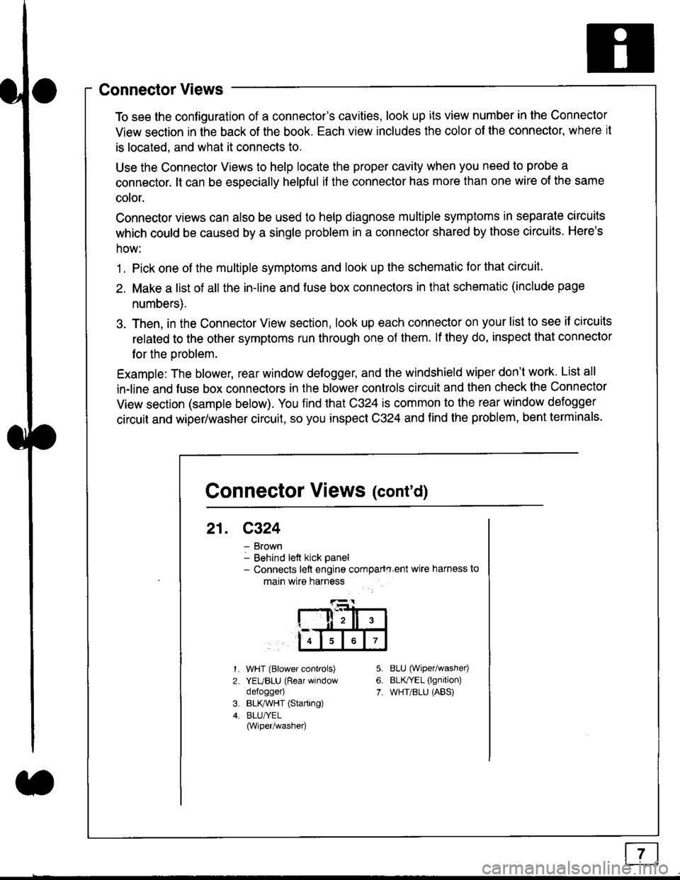
Connector Views
To see the configuration of a connector's cavities, look up its view number in the Connector
View section in the back of the book. Each view includes the color of the connector, where it
is located, and what it connects to.
Use the Connector Views to help locate the proper cavity when you need to probe a
connector. lt can be especially helpful if the connector has more than one wire of the same
cotor.
Connector views can also be used to help diagnose multiple symptoms in separate circuits
which could be caused by a single problem in a connector shared by those circuits. Here's
how:
1. Pick one of the multiple symptoms and look up the schematic for that circuit.
2. Make a list of all the in-line and fuse box connectors in that schematic (include page
numbers).
3. Then, in the Connector View section, look up each connector on your list to see il circuits
related to the other symptoms run through one of them. lf they do, inspect that connector
for the oroblem.
Example: The blower, rear window defogger, and the windshield wiper don't work. List all
in-line and fuse box connectors in the blower controls circuit and then check the Connector
View section (sample below). You find that C324 is common to the rear window defogger
circuit and wiper/washer circuit, so you inspect C324 and find the problem, bent terminals.
5.
6.
7.
1.
2.
WHT (Blower controls)
YEUBLU (Rear window
defogger)
BLK,ryVHT (Starting)
BLU/YEL(Wiper/washe0
8LU (Wiper/washed
BLfiEL (lgnition)
WHT/BLU (ABS)
Connector Views (cont'd)
21. C324
Brown
Behind left kick panel- Connects left engine compartry'ent wire harness to
main wire harness
ll,ll,
567
Page 1829 of 2189
In the "OHMS" range, the DVOM will measure
resistance between two points along a circuit.
Low resistance means good continuity.
Diodes and solid-state devices in a circuit can
make a DVOM give a false reading. To check
a reading, reverse the leads, and take a
second reading. lf the readings differ, the
component is affecting lhe measurement.
Jumper Wire
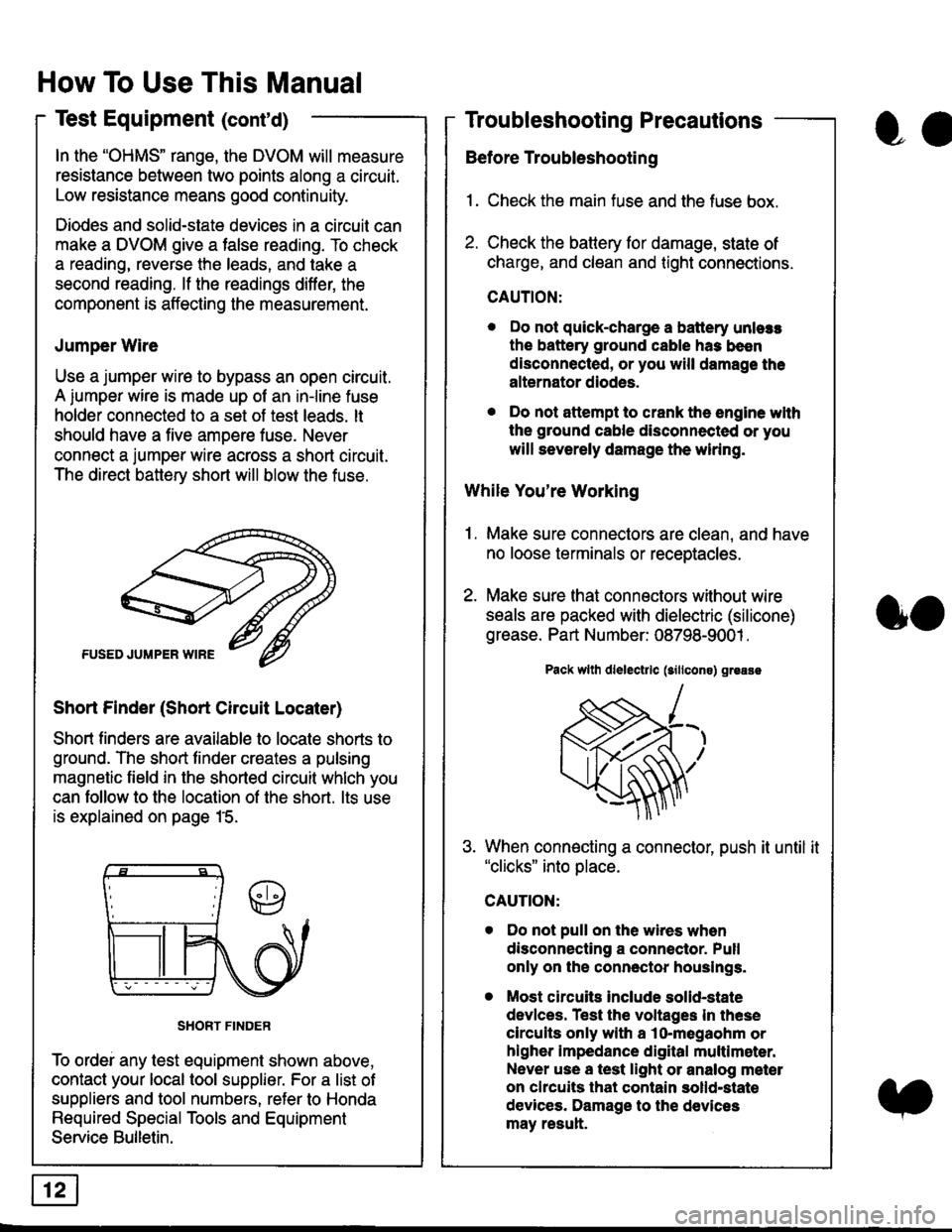
Use a jumper wire to bypass an open circuit.
A iumper wire is made up ot an in-line fuse
holder connected to a set of test leads. lt
should have a five amoere fuse. Never
connect a jumper wire across a short circuit.
The direct battery short will blow the fuse.
Short Finder (Short Circuit Locater)
Short finders are available to locale shorts to
ground. The short tinder creates a pulsing
magnetic field in the shorted circuit whlch you
can follow to the location of the short. lts use
is explained on page 15.
SHORT FINDER
To ordei any test equipment shown above,
contact your local tool supplier. For a list of
suppliers and tool numbers, refer to Honda
Required Special Tools and Equipment
Service Bulletin.
How To Use This Manual
Test Equipment (cont'd)
oa
Troubleshooting Precautions
Before Troubleshooting
1. Check the main fuse and the fuse box.
2. Check the battery for damage, state of
charge, and clean and tight connections.
CAUTION:
. Do not quick-charge a battery unlers
the battery ground cable has been
disconnected, or you will damage the
alternator diodes.
. Do not attempt to crank the engine wlth
the ground cable disconnected or you
will severely damage the wiring.
While You're Working
1. Make sure connectors are clean, and have
no loose terminals or receptacles.
2. Make sure lhat connectors without wire
seals are packed with dielectric (silicone)
grease. Part Number: 08798-9001 .
Pack wllh dlelectrlc (sillcons) greass
When connecting a connector, push it until it"clicks" into place.
Do not pull on the wires when
disconnecting a connector. Pull
only on the connector houslngs.
Most circuits Include solid-state
devlces. Test the voltages In these
circuits only with a lo-megaohm or
higher impedance digital multlm6ter.
Never use a test light or analog meter
on chcuits that contain solld-state
devices. Damage to the devices
may result.
oo
Page 1838 of 2189
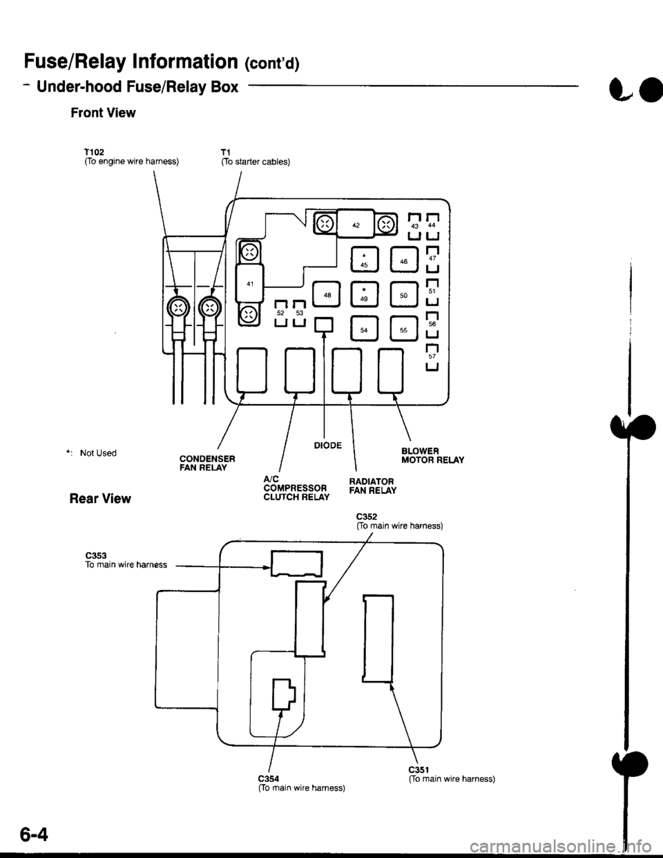
Fuse/Relay Information lcont'd)
- Under-hood Fuse/Relay Box
Front View
T'102(To engine wire harness)
LO
T1Oo starter cables)
*: Not Used
Rear View
c353To main wire harness
DE
tr
tr
tr
t-l
IJ
n
tJ
t-l51
IJ
n
IJ
n5T
IJ
[[o main wire harness)
6-4
ffo main wire harness)fto main wire harness)
Page 1840 of 2189

Ground-to-Components I ndex
f.,lONOTE: All ground wires are BLK unless otherwise noted.
GroundPageComponents or Circuit Grounded
Battery (BLKYEL)
Steering pump bracket
t+-rg ITransmission housing
l
G101
(-1)
G101
(-2)
14-2
and
14-3
ano
14-1
Powertrain or engine control module (PG1 and pG2 are BLK: LG1 and LG2 are
BRN/BLK), EGR control solenoid valve (CW, EGR valve and lift sensor (Dt6yS enginewith M,/T), Engine coolant temperature switch, pGM-Fl main relay, power steeringpressure switch (USA), Primary HO2S (D16Y5 engine with l\/,/T), Vehicle speed sensor,VTEC pressure switch (D16Y5/D16Y8 engines), CKF sensor (BRN/BLK), Transmission
control module (CYf) (Pc1 is BLK: LG1 is BRN/BLK)
Shielding betvveen the PCM or ECM and these components (all have BRN/BLK wires):
CKF sensor, TDC/CKP/CYP sensor. Primary and secondary heated oxygen sensors.
Knock sensor (CWDl6YB engine), Mainshaft speed sensor (AiT except CVT),
I Countershaft speed sensor (A/T except CVf)
Shielding between the TCM and these components (CVT) (all have BRN/BLK wires):
Drive pulley speed sensor, Driven pulley speed sensor, Secondary gear shaft
speed sensor
Powertrain or engine control module (PG1 and pG2 are BLK; LG1 and LGz are
BRN/BLK), EGR control solenoid valve (D16Y5 engine), EGR valve (Dt685), Engine
coolant temperature switch, Fuel pressure regulator shut-off solenoid valve (D1685),
PGM-FI main relay, Power steering pressure switch (USA), Vehicle speed sensor, VTECpressure switch (All except D16Y7 engine), CKF sensor (A
except 81642) (BRN/BLK)
Shielding between the PCM or ECM and these components (all have BRN/BLK wires):
CKF sensor, TDC/CKP/CYP sensor, Primary and secondary heated oxygen sensors,
Knock sensor (All except D16Y7 engine), i/ainshaft speed sensor (Arf except CW),
Countershaft speed sensor (A,/T except CVf), Drive pulley speed sensor (CW), Drivenpulley speed sensor (CVT), Secondary gear shaft speed sensor (CVf)
I Badiator fan motor, Right front parking/turn signat tight, Right headtight
G20214-4I Cruise control actuator, Left front parking/turn signal lights, Left headlight, Rear window
I washer motor, Windshield washer motor, Washer fluid level switch (,99-'00 Canada)
G401| +-o
and
14-7
Accessory power socket, Brake fluid level switch, Clutch interlock switch (M/T), Clutchswitch (lillT with cruise/D16Y5 engine with MfD, Combination wiper switch (Z wires),
Cruise control main switch, Cruise control unit, Dash lights brightness controller, Data
link connector, Daytime running lights control unit (Canada), Gauge assembly, Horn('96-'97 models), Integrated control unit, Interlock control unit (ArI), Keyless door lock
control unit ('99-'00 models with keyless), Moonroof close and open relays, Moonroof
switch, Park pin switch (A/r), Power window relay, Rear window defogger relay, Rear
window defogger switch ('96-'98 models), Steering lock, Stereo radio tuner (,96-,98
USA: LX, EX, and HX), Turn signal/hazard relay, Windshield wiper motor.....plus
everything grounded through G402
6-6
Page 1857 of 2189
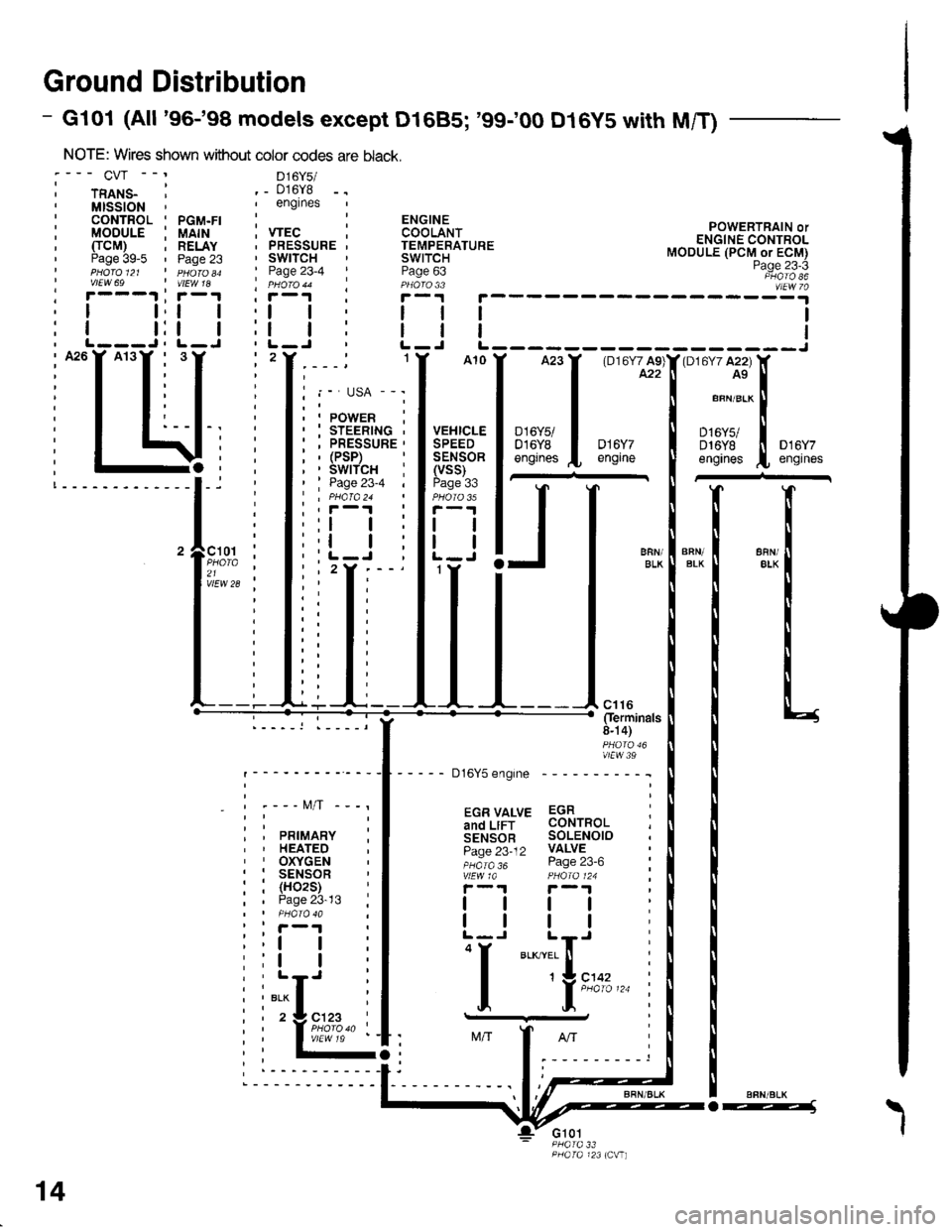
Ground Distribution
- Gl01 (All '96-'98 models except D1685; '99100 D16y5 with M/T)
NOTE: Wires shown without color codes
:--- CVr --' D16y5/
i rnlts_ ' ._ 016y8,MISSION',englnes
: CONTROL ' PGM.FI :: MODULE i UAIH ; VTEC, TTCM) ; RELAY . PRESSURE' Paae 39-5 ' Paoe 23 ' SWITCHI pHdro et ' n 6roao ' Page 23-4I vtEw 69 | vtEw 1a ' pHoro 44' r---.t ' r-1 I i-r
POWERTRAIN orENGINE CONTROLMODULE (PCM or ECM)Page 23-3PHATO 86vlEw 7a; r---1 ;r-1 , r, I t,t | ,l
: I t:t | :l, L---J, L-J ' L-, A26Y A13Y , 3,2
i T T: I I
I I, I t,,-I T T: T i
: I t:--I-. :
i I \li:; -4, ;!-------------l-i '
'lF;% :21 ,vlEw 28 ;
_ - t\4/T -
PRIMARYHEATEDOXYGENSENSOR(H02S)Page 23-13
ll
tl
"i[",..
14
o---1\
I
Page 1859 of 2189
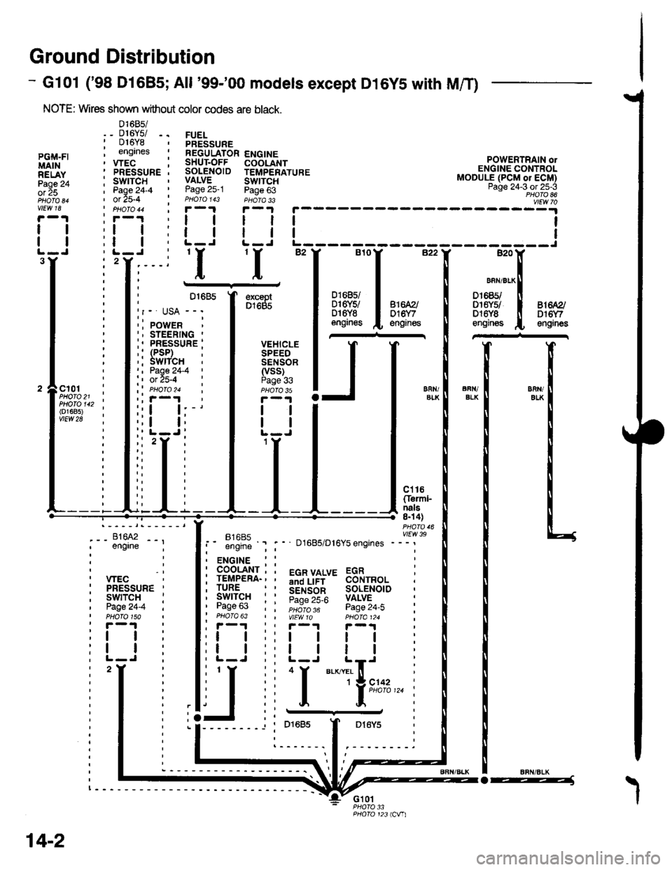
Ground Distribution
- Gl01 ('98 Dl685;All '99-'00 models except D16YS with M/T)
NOTE: Wires shown without color codes are black.
01685/_ D16Y5/ -.016Y8engrnes
.__-;,#'-_,--', engrne ;
, wEc: PRESSURE '
, swtTcH :I Page24-4 iI PHOTO 150: r -'l
:t | :
:l | :,L-J.
FUELPRESSUREREGULATOR ENGINESHUT.OFF COOLANTSOLENOID TEMPERATUREVALVE SWTTCHPage 25-1 Page 63PHOIO 143 PHOTA 33r-1F-.|
llll
lltlL-J L-J
POWERTRAIN olENGINE CONTROLMODULE (PCM or ECM)Page 24-3 ot 25-3PHOTO 86
----:y4
tl
tl
PGi,|.FIMAINRELAYPage 24ol 25
vlEw 18
tl
tl
3Y'I'I
excaptD1685
VEHICLESPEEDSENSOR(vss)Page 336FN/ELKERll/EIKcl01PHOTO 21PHOTO 142(o1685)vtEw 28
ct16Cferml-nals8n 4)
FltaFt( vttw 39t- .''iiti ' " D1685/D16Y5 engrnes ---'
t2
. ENGINE : :
i 933'?il-; i 5"T,Yf,*' 33i,"o, i
i lgfft" i I S.ir1".l^ soL€NorD :' Pase 63 : : ;;;;; - pase 24.i :' PHOTO 63 | | VtEWlO pHOIa124 ;, r-1 | , F-.t r-.r
:l | ;:l | ! | :;t | :,t | | | ;
j,f
ii T.__.,|,,,,,.
j
--
----- --l i otoas I Dr6y5 :
:------.1.--------.
14-2
o-----J