Connector a HONDA CIVIC 1996 6.G Owner's Manual
[x] Cancel search | Manufacturer: HONDA, Model Year: 1996, Model line: CIVIC, Model: HONDA CIVIC 1996 6.GPages: 2189, PDF Size: 69.39 MB
Page 254 of 2189
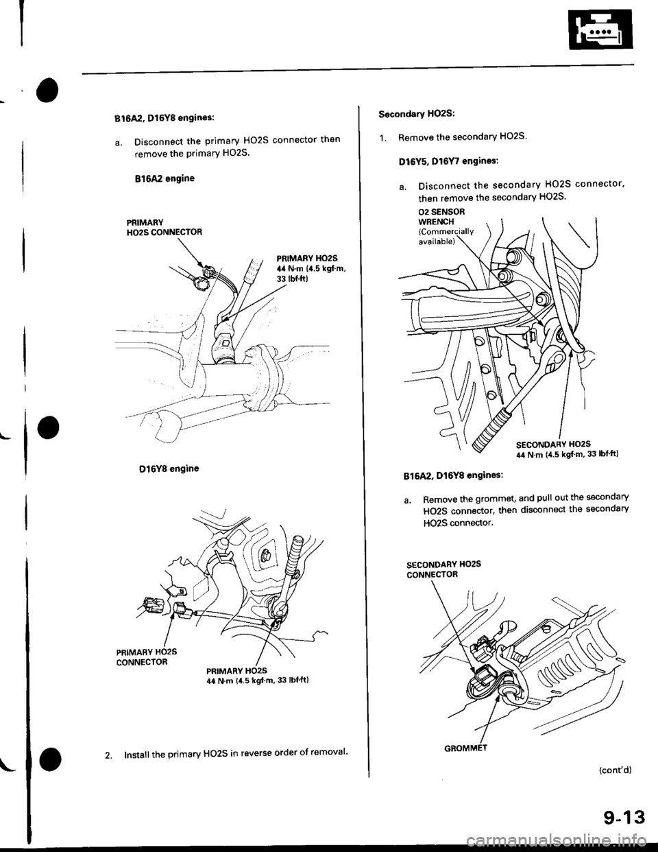
Bt6A2, Dl6Y8 engines:
a. Disconnect the primary HO2S connector then
remove the primary HO2S.
816A2 engine
D16Y8 engine
PRIMARYH02S CONNECTOR
PRIMARY HO2S44 N.m {4.5 kgt'm.33 lbf'ft)
L
2. Install the primary HO2S in reverse order of removal'
Secondsry H02S:
1. Remove the secondary HO2S
Dl6Y5, Dt6Y7 engines:
a. Disconnect the secondary HO2S connector.
then remove the secondary HO2S'
02 SENSOR
816A2, Dt6Y8 ongin6s:
a. Remove the grommet, and pull out the secondary
HO2S connector, then disconnect the secondary
HO25 connector'
SECONOARY H()2S
CONNECTOR
{cont'd)
9-13
Page 261 of 2189
Radiator
Replacement
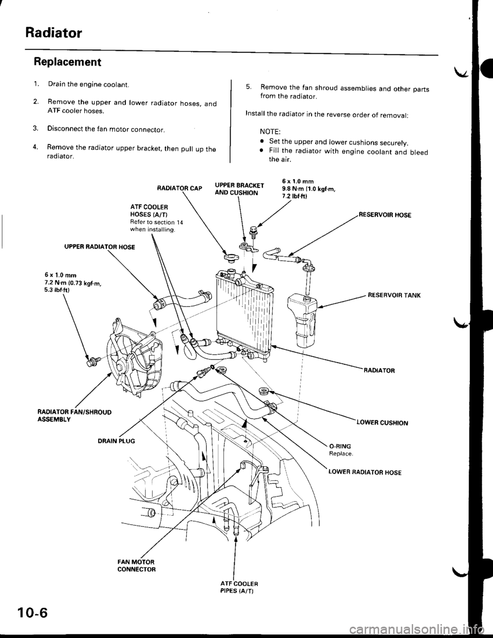
Drain the engine coolant.
Remove the upper and lower radiator hoses, andATF cooler hoses.
Disconnect the fan motor connector.
Remove the radiator upper bracket, then pull up theraotator,
RADIA
ATF COOLERHOSES (A/T)Refer to sectionwhen installing.
UPPER RAOIATOR HOSE
6x1.0mm7.2 N.m (0.73 kgf.m.5.3 tbf.ft)
1.
2.
3.
5. Remove the fan shroud assemblies and other partsfrom the radiator.
Install the radiator in the reverse order of removal:
NOTE:
. Set the upper and lower cushions securely.. Fill the radiator with engine coolant and bleedthe air.
6x1.0mmCAPY|lT,PS:|" i.i ru- ii b rgr.-,AND CUSHION7.2 tbr.ftl
14
(
I
RESEBVOIR TANK
RADIATOR
LOWER CUSHION
RAOIATOR FAN/SHROUDASSEMBLY
DRAIN PLUGO-RINGReplace.
LOWER RAOIATOR HOSE
ATF COOLERPIPES {A/T)
,iiiiii
10-6
Page 270 of 2189

!
Fuel and Emrsslons
SoecialToofs .....,...."..,. 11-2
Component Locations
lndex ....................., ......... 11-3
Svstem Description
Vacuum Connections ................,,..,.. ......... 11-12
Electrical Connections ...............,.,.,... ....... 11-29
System Connectors ........,.,.,.......................... 1 1-51
Troubleshooting
Troubleshooting Procedures ................. .. 11-81
Engine Control Module/PowertrainControl Module TerminalAfiangement ....,.,..... 11-88
Diagnostic Trouble Code Chart .................,., 11.97
How to Read Flowcharts .,.......................... . 11-103
PGM-Fl System
System Description ...... 11-10,1
Troubleshooting Flowcharts
Engine Control Module/PowertrainContlol Module ........ 11-107
Manitold Absolute Pressure Sensor .....'. . ... 11-115
fntake Air Temperatuie Sensor ..... . . ., . 11'121
Engine Coolant Temperatuae Sensol ........., 11-128
Throttle Position Sensor ...................,........... 11-132
Primary Heated Orygen Sensor (Sensor 1l ... 11-139
Secondary Heated Oxygen Sensor(Sensor 21.................................................... 1 1-153
Heated Oxygen Sensor Heater ...................,. 11-157
Fuel Supply System ...... 11-164
Random Mislire ......., ..11-166
Misfire Detected in One Cylindsr ................. 11-167
Knock Sensor .,.,............ 11-170
CKP/TDC/CYP Sensor ................................... 11'172
Vehicle Speed Sensor ...........,......,...,.,........... 1t-176
Barometric Pressure Sensor ...............,......... I 1-178
Electrical Load Detector,.,,............................ 1 1-179
CKF Sensor .................... 11-183
ECM/PCM Internal Circuit ............................. I 1-188
A/T Signal {TMA/TMBI .................................. I 1-189
ldle Control System
System Doscriplion ............ 11-190
Troubleshooting Flowcharts
ldle Control System ...... 11-192
ldle Air Control Va1ve .................................... I 1-19i1
Starter Switch Signal .................................... 1 1'202
Air Conditioning Signal ................................. 11'201
Ahernator FR Signal .................................... . 1 1-208
BrakeSwitch Signal ..................................... f 1"210
Power Sleering Prossure Switch Signal ......11-212
A/T Gear Position Signal ............................... 11-216
Clutch Swiich Signal ................................-.... 11-214
ldte Speed Setting . .............11-220
Fuel Supply System
Fuel Lines .,...................,.,.,.,11-221
Fuef Tube/Ouick-Connect Fittings ..........,.,........ 11 -227
System Description ....'.... 11-230
Fuel Pressure .......,.,,........... 11-230
Fuef fniectors ......................11-232
Fu€f Pressure Regulator .....,.......................'...,. 11-231
Fuef Fifter ............................11-235
Fuel Pump .............'.......'.... 11-236
PGM-FI Main Relay .............11'237
Fuel Tank ................ ....,...'.'.' 11'211
Intake Air System
System Description ....-.-.....11-243
Air Cfeaner ...........,......."". .11-211
Throttle Cable .....................11-211
Throttfe Body ........ ..'... . . .,.11-211
Fuel Iniestion Air Control System ,.,.,....-........... 11-250
Emission Control System
System Description .-..........11-252
Taifpip€ Emission ...............11-252
Three Way Catafytic Convert€r ............,.,,.,.,.,.... 11 -252
Exhaust Gas Racirculaiion System ...,.,,,,.,.,.,.,,. 11'254
Positive Crankcas€ Ventilation System .... . . .. 11-266
Evaoorative Emission Controls ..................,,..,.,. 11 -267
Page 271 of 2189
Special Tools
a\-Special Tools
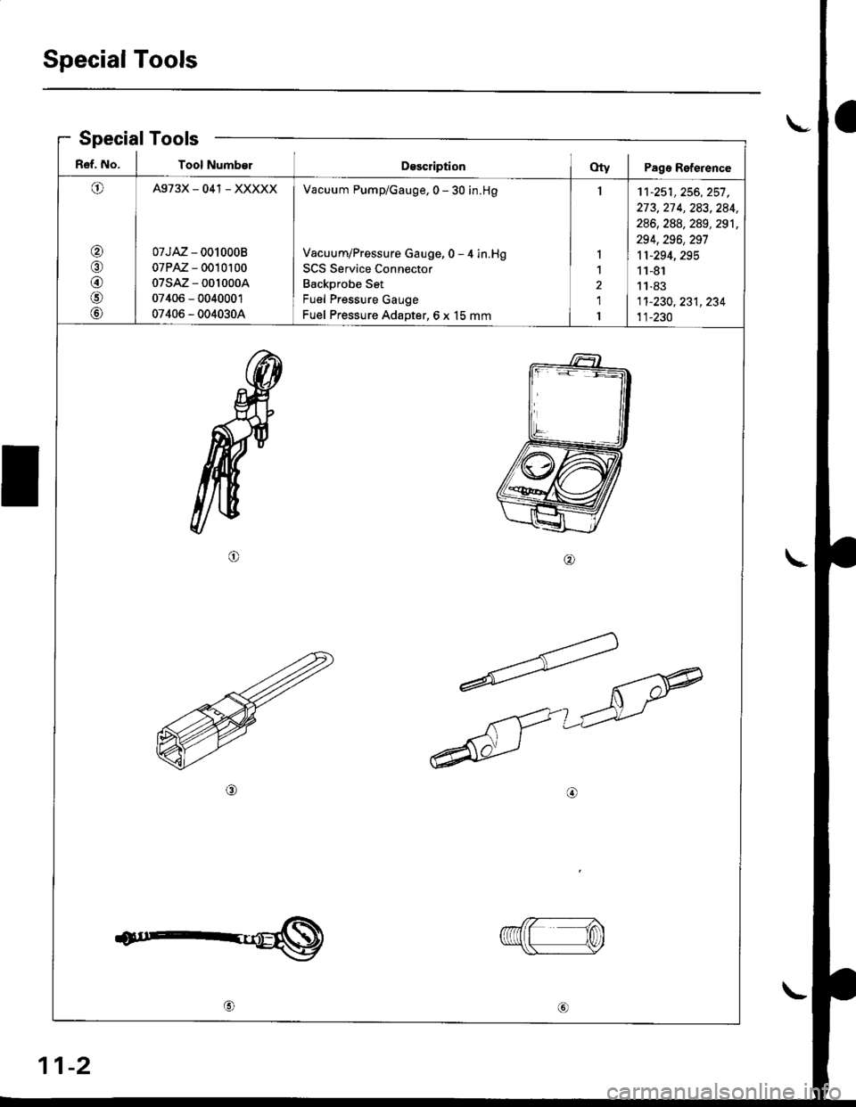
R€f. No. I Tool NumberDsscriptionOty I Pagr Reference
O
@/n
@
@
@
A973X_041 _ XXXXX
07JAZ - 0010008
07PAZ - 0010100
07sAz - 001000A
07406 - 0040001
07406 - 0040304
Vacuum Pump/Gauge, 0 - 30 in.H9
Vacuum/Pressure Gauge, 0 - 4 in.Hg
SCS Service Connector
Backprobe Set
Fuel Pressure Gauge
Fuel Pressure Adapter,6 x 15 mm
I
I
1
2
1
I
11-251,256, 257 ,273,27 4, 283,284,
286, 288, 289, 291,
294,296,297
11-294,295
11-81
11-83
1'�t-230, 231, 234
11-230
ta
1n\Y
11-2
Page 276 of 2189
I
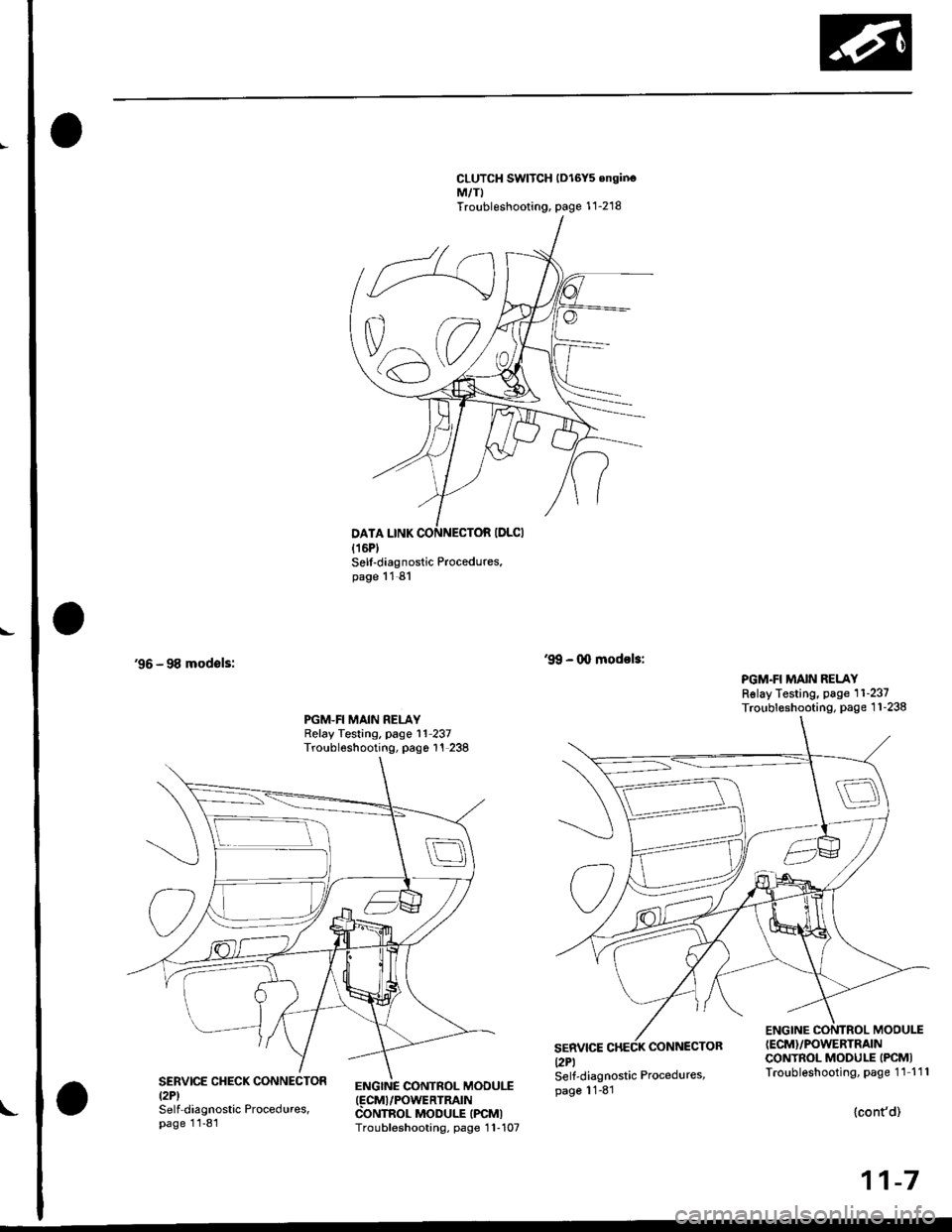
CLUTCH SWITCH lDl6Y5 onginoM,/TITroubleshooting, page 1 1-218
'96 - 98 modsls:
Sell-diagnostic Procedures.page 11 81
ENGINC CONTROL MOOUI.T(FCMI/POWERTRATN
CONTROL MODULE IPCMITroubleshooting, page 1 1-107
'9!, - 0o modol3:
PGM.FI MAIN RELAYRslay Testing, page 11-237Troubleshooting, page 1 1-238PGM.FI MAIN RELAYRelay Testing, page l1 237Troubleshooting, pago 1'! 238
SERVICEl2Pl
CONNECTOR
ENGINE CONTROL MODU1T(ECM}/POWERTRAIN
CONTROL MODULE IPCMITroubleshooting, page 11 111SERVICE CHECK CONNECTORtzPlSelf-diagnostic Procedures,page 11-81
Self-diagnostic Procedures,page 11-81
{cont'd)
11-7
Page 320 of 2189
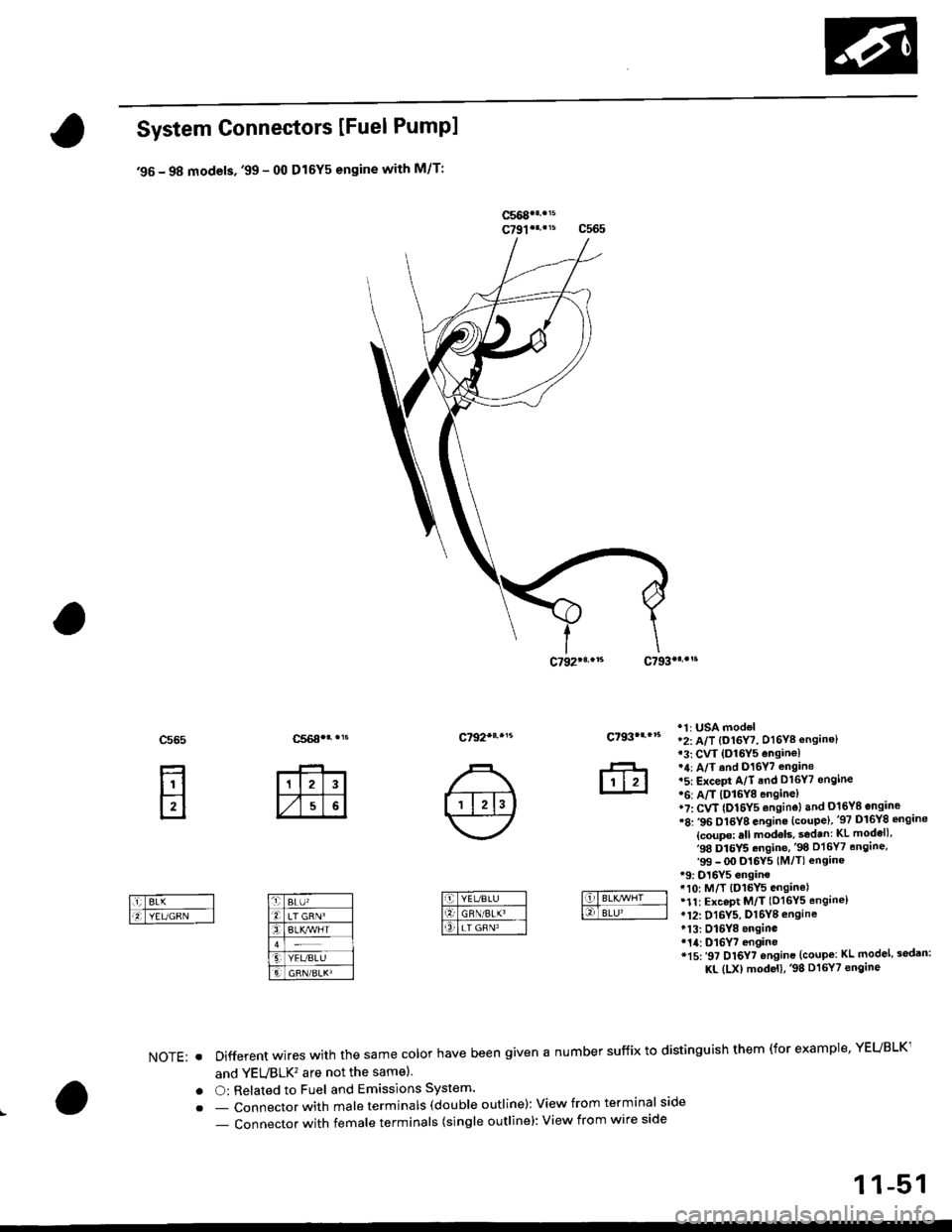
System Connectors [Fuel Pumpl
'95 - 98 models, '99 - 00 Dl6Y5 engine with M/T:
ffi
c565
E
c792*r,.'5c793|.,.s
*1r USA mod€l'2: A/T {O16Y7, D16Y8 ensine}13: CVT {O16Y5 ensin€l*4: A/T ind D16Y7 .ngane*5: ExceFt A/T end D16Y7 engine'6: A/T lDl6Y8 enginel*7: CvT (Dl6Y5 enginoland 016Yg engine'8: ,96 Dl6YB engine {coupe),'97 Dl6Y8 sngine
{coupe: sll models, s€d.nr KL modell,'98 Dl5Y5.ngine,'98 D16Y7 engine,'99 - OO Dl6Y5 (M/Tl enginer9: D16Y5 onginet10: M/T {D15Y5 ensinelr1t: ExceDt M/T (D16Y5 engine)tl2: D16Y5, Dl6Yg engine*13: Dl6Y8 enginer14: D16Y7 engine*15:'97 Dl6Y7 ensine {coupe: KL model, sodan:
KL (LX) modeu,'98 Dt6Y7 engine
NOTE: . Different wires with the same color have been given a number suffix to distinguish them (for example' YEUBLK1
and YEVBLK'� are not the samel.
. O: Related to Fuel and Emissions System'
. - Connector with male terminals (dou ble outline): View f rom term inal side
- Connector with female terminals (single outline): View from wire side
c7931...15
ffi
1 1-51
Page 321 of 2189
![HONDA CIVIC 1996 6.G Owners Manual System Description
System Connectors IEngine Compartment]
96 - 98 Dl6Y5, Dl6Y8 engin€, 99 - O0 Dt6y5 engine wirh M/f:
I
:
ir
I
11-52
\ HONDA CIVIC 1996 6.G Owners Manual System Description
System Connectors IEngine Compartment]
96 - 98 Dl6Y5, Dl6Y8 engin€, 99 - O0 Dt6y5 engine wirh M/f:
I
:
ir
I
11-52
\](/img/13/6068/w960_6068-320.png)
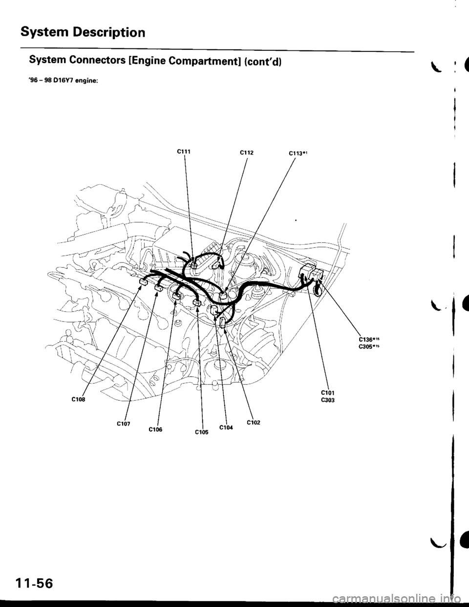
System Description
System Connectors IEngine Compartment]
'96 - '98 Dl6Y5, Dl6Y8 engin€, '99 - O0 Dt6y5 engine wirh M/f:
I
:
ir
I
11-52
\
Page 322 of 2189
![HONDA CIVIC 1996 6.G Owners Manual Cl0,r{C.nadal
rfr]
l6mrrrnru IElilrwA----llTltHtBtu__l
:lo.
llrl
lrl.l
c109..
rfrtr
16lonl -l
l@LYEUBLK Ibfgl-rcgtu---l
c102
rTrtt
l6lwtr,eED _-l
E|BFIvBLK -l
l6lga-tnEcl--l
c105
Etr
c106
ffi
c HONDA CIVIC 1996 6.G Owners Manual Cl0,r{C.nadal
rfr]
l6mrrrnru IElilrwA----llTltHtBtu__l
:lo.
llrl
lrl.l
c109..
rfrtr
16lonl -l
l@LYEUBLK Ibfgl-rcgtu---l
c102
rTrtt
l6lwtr,eED _-l
E|BFIvBLK -l
l6lga-tnEcl--l
c105
Etr
c106
ffi
c](/img/13/6068/w960_6068-321.png)
Cl0,r{C.nadal
r'fr]
l6mrrrnru IElilrwA----llTltHtBtu__l
:lo.
l'lrl
lrl.l
c109..
r'frtr
16lonl -l
l@LYEUBLK' Ibfgl-rcgtu'---l
c102
r'Trtt
l6lwtr,eED' _-l
E|BFIvBLK -l
l6lga-tnEcl--l
c105
Etr
c106
ffi
c114
fr
c108
ffi
c107
ffi
Bffiffi
c113*1
ffiffi
,DGRN/BLK'(9LT GRN?BLU]38
NOTE: . Different wires with the same color have been given a number suffix to distinguish them (for 6xample, YEUBLK1
and YEUBLK'�are not the same).
. O: Related to Fuel and Emissions Syst€m'
. - Connector with male terminals (double outline): View from terminal side
- Connector with female terminals (single outline): View trom wire side
(cont'd)
11-53
c1a2.r
fr
Page 324 of 2189
![HONDA CIVIC 1996 6.G Owners Manual c1t7
rffi]
fTBLir-llO BLX,YEI Il6lEtu^tHr__-l
c125
ffi
16lwrrin+o tliSlcFN/BLK I16T8LK^Er-- l
-.,IBaK,r /Hr. I
c141*
___l:t_
l-lrl
I LT GRNA/VHT I
f€,]-BLK,rEf-__l
cl16c1t5cl11
c128.
ffi
161 HONDA CIVIC 1996 6.G Owners Manual c1t7
rffi]
fTBLir-llO BLX,YEI Il6lEtu^tHr__-l
c125
ffi
16lwrrin+o tliSlcFN/BLK I16T8LK^Er-- l
-.,IBaK,r /Hr. I
c141*
___l:t_
l-lrl
I LT GRNA/VHT I
f€,]-BLK,rEf-__l
cl16c1t5cl11
c128.
ffi
161](/img/13/6068/w960_6068-323.png)
c1t7
r'ffi]
f'TBLir-llO BLX,YEI Il6lEtu^tHr__-l
c125
ffi
16lwrrin+o' tliSlcFN/BLK I16T8LK^'Er-- l
-.,IBaK,r /Hr. I
c141*'
___l:t_
l-lrl
I ' LT GRNA/VHT I
f€,]-BLK,rEf-__l
cl16c1t5cl11
c128.'
ffi
1618r-uf/EL-_]
161-cfl,avHr -l
cl45rrc
Ft_
l-,T,ITd
t_-Ttli I
c127*'
fr
IFFEc'--__l
ftlwHn-'_l
-c,1*
t-El-rl1 I 2l 3l
l.l
'ul
16lvvrrr/BtK---.llglcnN/BrK, IlO YEvBru I16r lsrK' IET- --
f+plr-, -_l
c118"
ffi
trl-clrl---]latl IBLU, I
c126*'
ffi
fOTwHn-_-llOlREo. I
:.trn
.EL
[tT,l.l
v
I i wHl/8tK IlETc RNi BLF--l
ET-YtrrrruBiu-__-l
q]54't
r,f,"|
I i IBLK4/VHT IlOlsLK I
IO LGRN/RED I
c112
fr
c120
tdl cnN/YEt--l
NOTE: . Different wires with the same color have been given a number suffix to distinguish them (for example, YEUBLK'
and YEUBLIC are not the same).
. O: Belated to Fuel and Emissions System'
. - Connector with male terminals (double outline): View from terminal side
- Connector with female terminals (single outlins): View from wire side {cont'd}
c121*'
ffi
c123
ffi
c1a0rt
fr
l6lgrf,---_-lIOIREB I
c13!,.f
E
c122
iYEUGFNoBLU5REO!8L(,
YEL'98tu
510BLK/YEL
c351
1 1-55
Page 325 of 2189
System Description
System Connectors lEngine Compartmentl {cont,dl
36 - 98 D15Y7 €ngine:
\
'l'
1 1-56
\,