idle sensor HONDA CIVIC 1996 6.G Owner's Manual
[x] Cancel search | Manufacturer: HONDA, Model Year: 1996, Model line: CIVIC, Model: HONDA CIVIC 1996 6.GPages: 2189, PDF Size: 69.39 MB
Page 397 of 2189
PGM-FI System
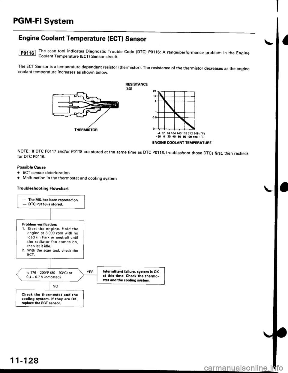
Engine Coolant Temperature (ECTI Sensor
The scan tool indicates Diagnostic Trouble code (DTC) P0116; A range/performance problem in the EngrneCoolant Temperature (ECT) Sensor circuit.
The ECT Sensor is a temperature dependant resistor (thermistor). The resistance of the thermistor decreases as the enginecoolant temperature increases as shown oetow.
RESISTANCE(ko)
NOTE: lf DTC P0117 and/or P01'18 are stored at the same time as DTCfor DTC P0116.
Possible Cause
. ECT sensor deterioration. Malfunction in the thermostat and cooling system
Troubleshooting Flowchart
-a 32 68 r0a la0l?6 2t2 2481'rr-20 o 20 ao o D r@ Il, r'c)
ENGINE COOLANT IEMPERATURE
P0116, troubleshoot those DTCS first. then recheck
11-128
THERMISTOR
- The MIL has bogn reported on.- DTC P0116 is stored.
Problem verification:1. Start the engine. Hotd theengine at 3,000 rpm with noload (in Park or neutral) untilthe radiator fan comes on,then let it idle.2. With the scan tool, check the
Intermiftent lailure. system is OKai thi. time. Ch.ck the thc.mo-stat 6nd thc cooling system.
is 176 200'F {80 - 93'C)or0.0-0.TVindicated?
Check the thermostat and thecooling system. ll they als OK,raplace the ECT sensor.
Page 409 of 2189
PGM-FI System
(From page 11-139)
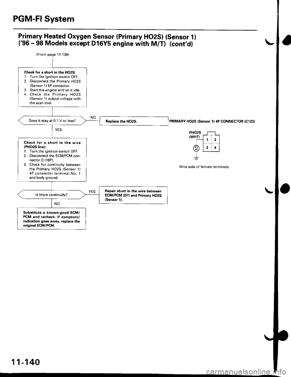
Check for a shon in the HO2S:1. Turn the ignition switch OFF.2. Disconnect the Primary HO2S(Sensor 1) 4P connector.3. Start the engine and let it idle.4. Check the Primary HO2S(Sensor 1)output voltage withthe scan tool,
Does it stay at 0.1 V or less?
Check for a short in lhe wire(PHO2S linel:1. Turn the ignition switch OFF.2. Disconnect the ECM/PCM con-nector D ('l6P).
3. Check for continuity betweenthe Primary HO2S lsensor 1)4P connector terminal No. 1and body ground.
Repair short in lhe wire b6tw6enECM/rcM (D7) and Primary llO2S{Sensor 1}.
Substitute a known-good ECM/PCM and recheck. ll symptom/indication goes awry, replaco theoriginal ECM/PCM.
Primary Heated Oxygen Sensor (Primary HO2S) (sensor 1l
('96 - 98 Models except Dl6Y5 engine with M/T) (cont'dl
PRIMARY HO2S lsonsor 1l ,tP CONNECTOR lC123l
Wire side of female terminals
11-140
Page 411 of 2189
PGM-FI System
Primary Heated Oxygen Sensor (Primary HO2SI (Sensor 1)
('99 - 00 Models except Dl6Y5 engine with M/T) (cont'd)
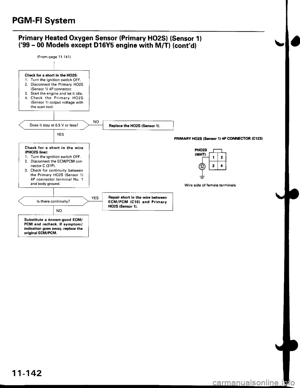
PRIMARY HO2S {S€oror 1} 4P CONNECTOR lc123l
PHO2S f----l,wHl_l:-f;-l
0ffi
_L
Wire side of female terminals
(From page 11 141)
Chock fo. a shori in the HO2S:1. Turn the ignition switch OFF.2. Disconnect the Primary HO2S(Sensor 1i 4P connector.3. Stan the engine and let it idle.4. Check the Primary HO2S(Sensor 1) output voltage withthe scan tool.
Does it stay at 0.5 V or less?Roplaco the HO2S (Sensor 1).
Check tor a short in the wire{PHO2S linel:1. Turn the ignition switch OFF.2. Disconnect the EcltI/PcM con-nector C {31P).3. Check for continuity betweenthe Primary HO2S lsensor 1)4P connector terminal No. 1and body ground.
ReDair shorl in the wi.e betweenECM/PCM (Cl61 and PrimaryHO2S (Sercor 11.
Substitute a known-good ECM/PCM and recheck. lf symptom/indication goes away, replace theoriginal ECM/PCM.
11-142
Page 417 of 2189
PGM-FI System
Primary Heated Oxygen Sensor (Primary HO2SI (sensor l)
(Dl6Y5 engine with M/T) (cont'd)
(From page 1l-147)(From page 11 147)
(To page 11 149)
{GRN/BLK}
(GRN/8I-K}
(To page 11-149)
11-148
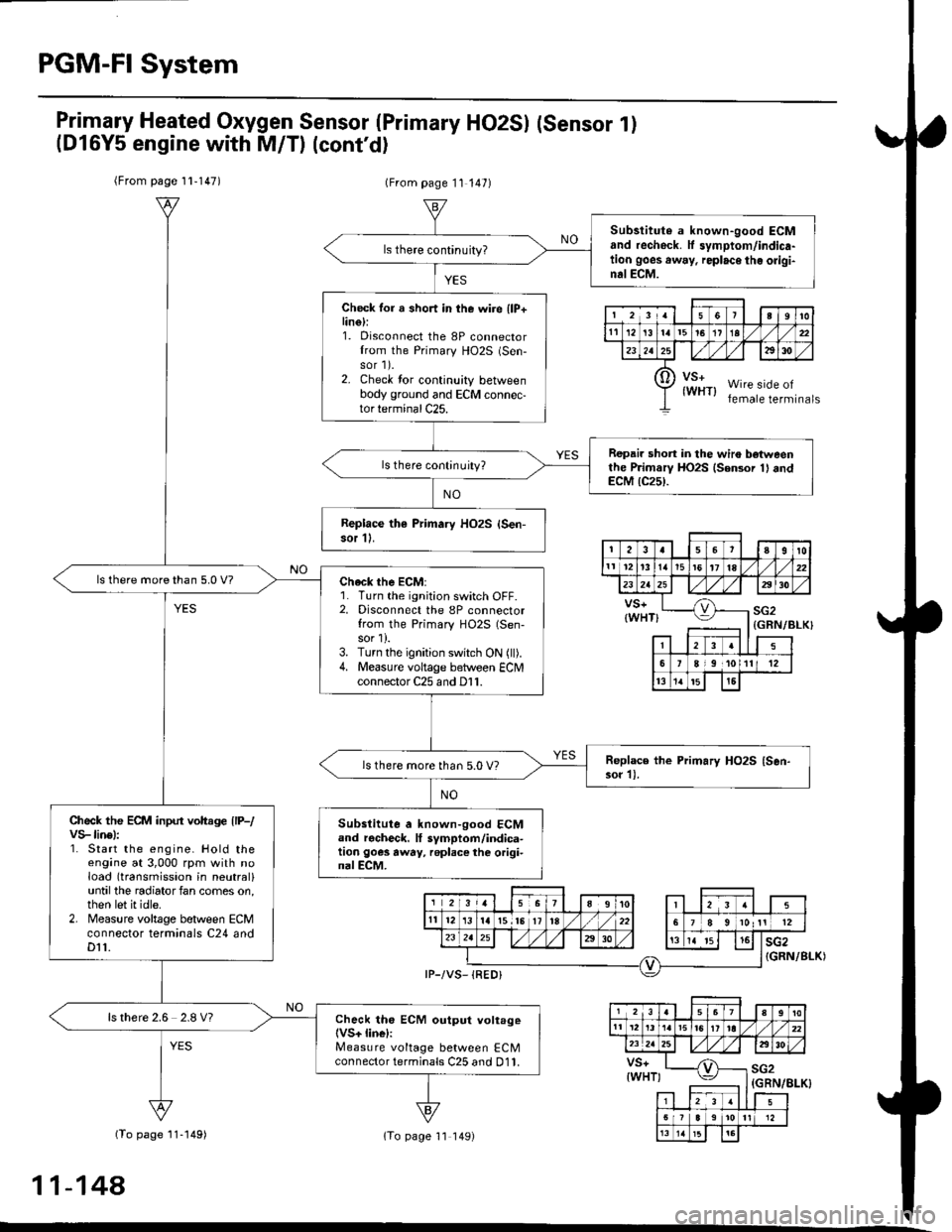
Substitute a known-good ECMand rechock. tf symptom/indicr-tion goes away, replace the origi-nalECM.
Check for a short in the wire llP+lin6):1. Disconnect the 8P connectorIrom the Primary HO2S (Sen-
sor 1).2. Check tor continuity betweenbody ground and ECM connec-tor terminal C25.
Repair short in the wiro botweenthe Primarv HO2S {Sensor 1} andECM {C25}.
Replace th€ Primary HOzS {Sen-sor 11.
| 2 3ra1a9to
tl 12t516111a
p ffi;r, w''.""i0"or.I lemate lerml
ls there more than 5.0 V?check the EcM:1. Turn the ignition switch OFF.2. Disconnect the 8P connectorfrom the Primary HO2S (Sen-
sor 1).3. Turn the ignition switch ON (ll).4. Measure voltage between ECN4connector C25 and D11.
ls there more than 5.0 V?
Check the ECM input voltage llP-/vS-linel:1. Start the engine. Hold theengine at 3,000 rpm with noload (transmission in neutral)untilthe radiator fan comes on,then let it idle.2. Measure voltage between ECMconnector terminals C24 andDt1.
Subslitute a known-good ECMand rgcheck. It symptom/indica-tion goes away, repl.ce the origi-nal ECM.
ls there 2.6 2.8 V?Check th6 ECM output voltage(VS+ linel:Measure voltage between ECMconnector terminals C25 and D11.
7a9t0It 12t3t6'11ta
VS+{WHT}sG2
235
,9 ,101l12
l3'tat515
1 2i35a9t0't2'ttt5ttrl22
VS+{WHT)sG2
23
6lt9ll1315
Page 431 of 2189
PGM-FI System
I
a
a
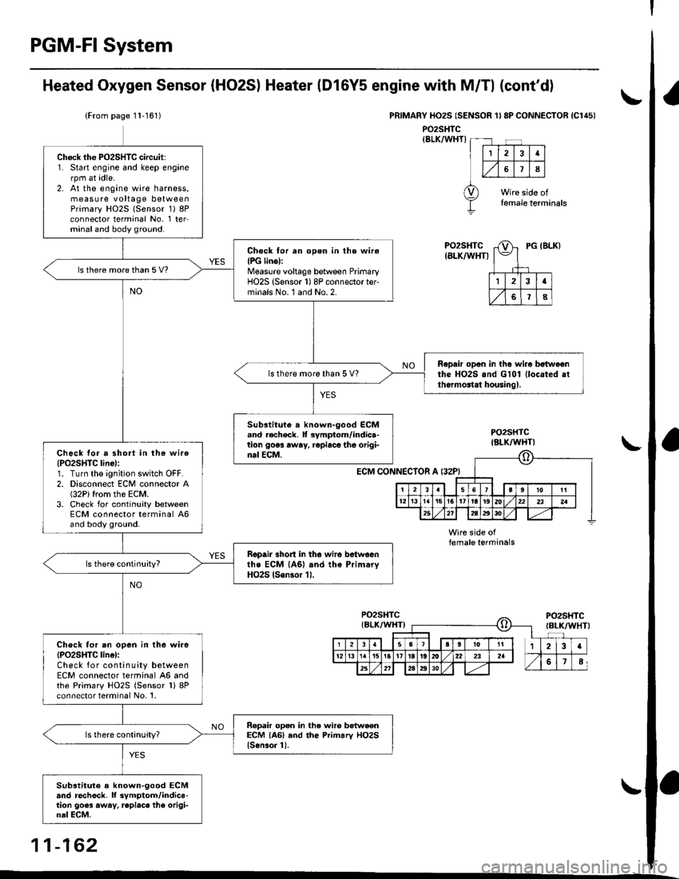
Ch6ck the PO2SHTC circuit:1. Start engine and keep enginerpm at idle.2. At the engine wire harness,measure voltage betweenPrimary HO2S (Sensor 1) 8Pconnector terminal No. 1 terminal and body ground.
Check for an open in the wire(PG linellMeasurc voltage between PrimaryHO2S (Sensor 1) 8P connector ter-minals No. l and No.2.
ls there morethan 5 V?
Repair opon in the wi.o bEtwoonthe HO2S.nd G101 (located atth.rmonat housingl.
ls there more than 5 V?
Substitule a known-good ECM.nd .echeck. lt 3ymptom/indica-tion 906! rwry, roplace the origi-nal ECM,Check lor a short in the wire
{PO2SHTC line):1. Turn the ignition switch OFF.2. Disconnect ECM connector A(32P)trom the ECM.3. Check for continuity betweenECM connector terminal 46and body ground.
Ropair 3hort in tho wire betwoenthe ECM {46} and the Prim.ryHO2S lson3or 11.
Check for an open in the wire(PO2SHTC linel:Check for continuity betweenECM connector terminal 46 andthe Primary HO2S (Sensor 1)8Pconnector terminal No. 1.
Repair opsn in the wir6 botweenECM {A6} .nd the Primary HO2Slsonror 1).
Substituto a known-9ood ECMand rech6ck. lf symptom/indica-tion goes away, replace the origi-nal ECM.
Heated Oxygen Sensor (HO2S) Heater (Dl6Y5 engine with M/Tl (cont'd)
(From page 11-161)PRIMARY HO2S (SENSOR 1} 8P CONNECTOR {Cl45I
PO2SHTC{BtK/WHT)
PO2SHTCIALK/WHTI
ECM CONNECTOR
female terminals
11-162
\.
!
\
A {32P}
o
6I9l roIt
12t3l5t61't8t9a221 232a
252'2aEito,1| ---
Page 439 of 2189
PGM-FI System
Knock Sensor (KSl ('96 - 98 D16Y5 engine with CW and'96 - 98 D16Y8
engine)
Forr-l I,3,.""""
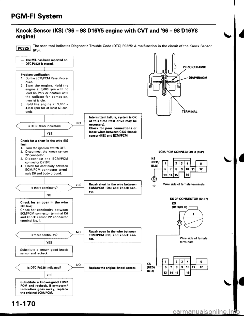
tool indicates Diagnostic Trouble Code (DTC) P0325: A malfunction in the circuit of the Knock sensor
DIAPHRAGM
ECM/PCM CONNECTOR D {16PI
KS 2P CONNECTOR (Cl371
KS(RED/BLUI
KSIRED/BLU)
The MIL has bgen roportsd on.DTC PO:t25 is stored.
Problom veiilication:1. Do the ECM/PCM Reset Proce-oure,2. Start the engine. Hold theengine at 3,000 rpm with noload (in Park or neutral) untilthe radiator tan comes on,then let it idle.3. Hold the engine at 3,000 -
4,000 rpm tor at least 60 sec-onds.
Intermittenl fsilu16, 3y3l6m b OKat thi3 timg lteat drivo mav banoc63saryl.Chock tor poor conneclioni orloose wire3 b€twccn C137 {knocklen3or (KS)l and ECM/PCM.
ls DTC P0325 indicated?
Check for a short in tho wire {KSlinel:1. Turn the ignition switch OFF.2. Disconnect the knock sensor2P connector,3. Discon n ect the ECM/PCMconnector O (16P).
4. Check for continuity betweenECM/PCM connector termi-nals D6 and body ground.
Reo.ir 3hort in the wire betweenECM/PCM {DG) .nd knock 3.n-
Chock for an open in the wire(KS linel:Check for continuity betweenECM/PCM connector torminal D6and knock sensor 2P connectorterminal No. l.
Ropair open in the wire bgtweonECM/PCM lD6l and knock sen-3('t.ls there continuity?
Substitute a known-good knocksensor and recheck.
Rsplace th. o.igin.l knock s€nsor.
Substitute a known-good ECM/PCM end recheck. lf 3ymptom/indication goes rway, replacerhe original ECM/PCM.
Wire side of female terminals
1\
I
tert
,_-
eslnini
,--tl
le oI temrlsal€
121
189't01t12
13l4t5t6
11-170
Page 440 of 2189
Knock sensor (Ks) r99 - 00 D16Y5 engine with cw, '99 - 00 D16Y8 engine and
816A2 engine
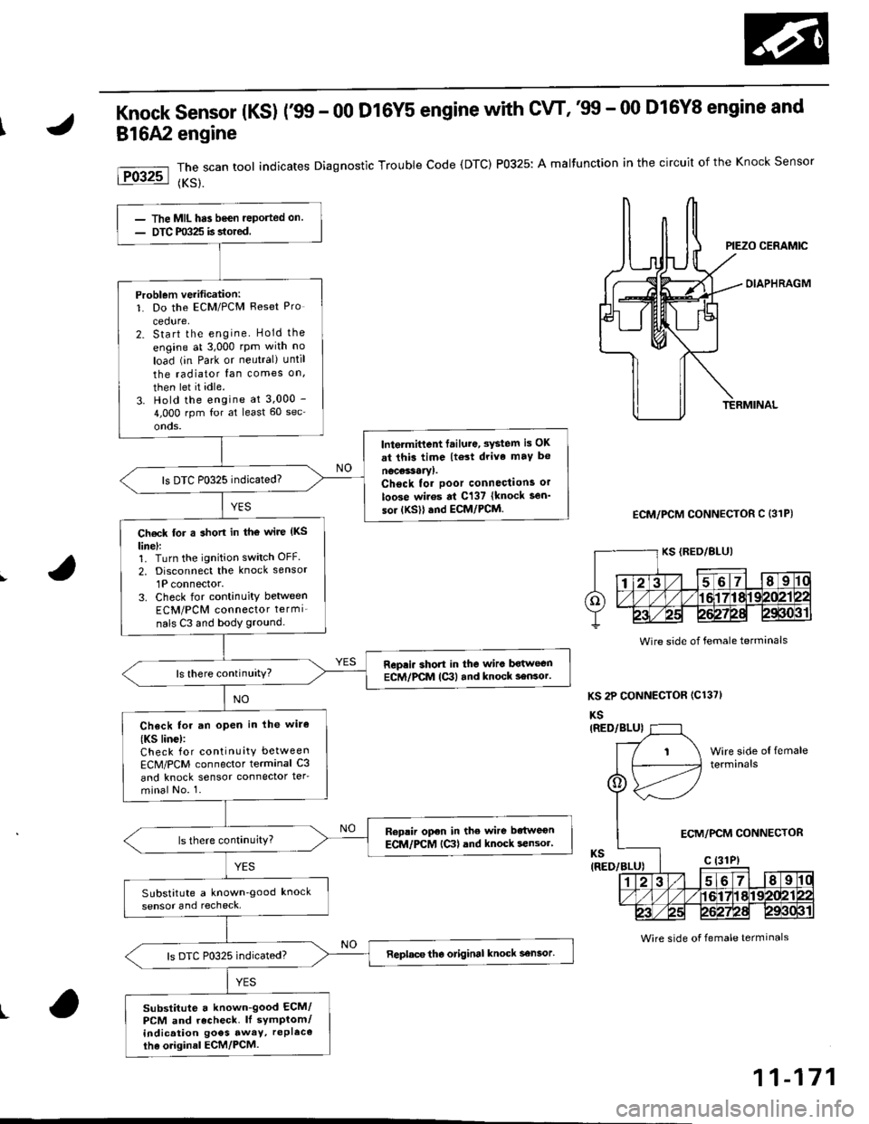
The scan tool indicates Diagnostic Trouble Code (DTC) P0325: A malfunction in the circuit of the Knock Sensor
{KS}.
OIAPHRAGM
ECM/PCM CONNECTOR C (31P)
KS 2P CONNECTOR (C1371
KS
Wire side of female terminals
t
The MIL has been reported on.
DTC m325 is stored
Problem verification:1. Do the ECM/PCM Reset Pro
cedure,2. Start the engine Hold the
engine at 3,000 rpm with no
load (in Park or neutral) until
the radiator fan comes on,
then let it idle.
3. Hold the engine at 3.000 -
4,000 rpm for at least 60 sec'
onds.
lntermittent failure, system is OK
at thi3 time lt€3t drive maY b€
nocessaryl.Chsck tor poor connections or
loose wiros at C137 {knock sen'
sor {KSll and ECM/PCM.
ls DTC P0325 indicated?
Ch€ck for a short in tho wire (KS
linel:1. Turn the ignition switch OFF.
2, Disconnect the knock sensor
1P connector.3. Check for continuity between
ECM/PCM connector termi_
nals C3 and body ground.
Repri. short in the wiro bqtwecnECM/PCM lc3l and knock 3ensor.ls there continuity?
Check for an open in lhe wire
{KS linc):Check for continuity between
ECM/PCM connector terminal C3
and knock sensor connector ter-
minal No. 1.
Replir open in the wire bdtweon
ECM/PCM {Ctl and knock sensor'
SubstitLrte a known'good knock
sensor and recheck,
Replace tho otiginal knock sensor.
substitute a known-good ECM/PCM and recheck. ll symptom/indication goes awaY, rePl6co
tha o.iginal ECM/PCM.
Wire side of female terminals
ECM/PCM CONNECTOR
11-171
Page 447 of 2189
PGM-FI System
Barometric Pressure (BAROI Sensor
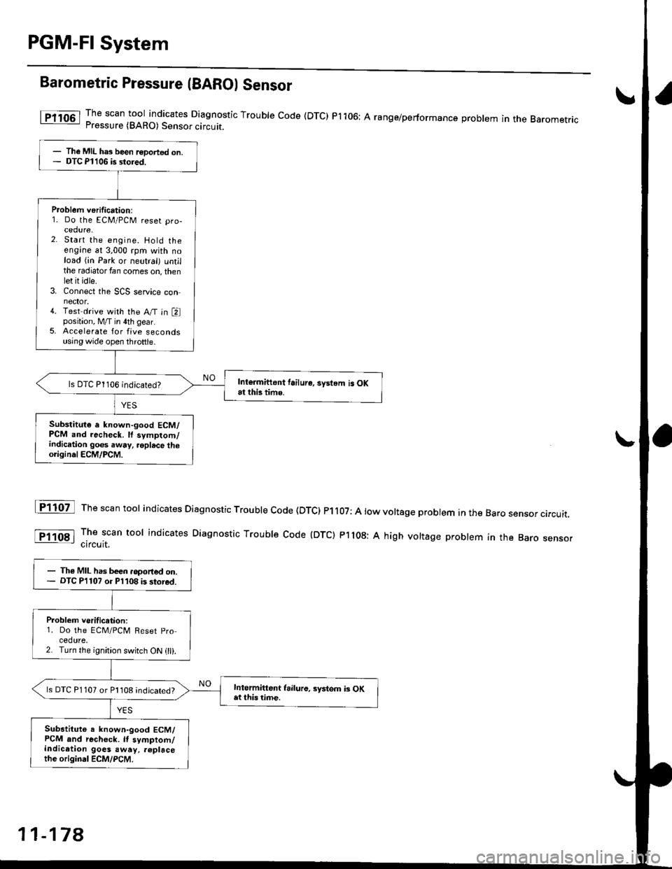
The scan tool indicates Diagnostic Trouble code (DTC) Pi106: A range/performance problem in the BaromerrrcPressure (BARO) Sensor circuit.
The scan tool indicates Diagnostic Trouble code (DTc) P1107: A low voltage probtem in the Baro sensor circurr.
The scan tool indicates Diagnostic Troubre code {DTC) p1108: A high vortage probrem in the Baro sensorcircuit.
fF1lot
tPlloal
The MIL ha3 been r€Dortsd on.DTC Pl106 is stored.
Problem verification:1. Do the ECM/PCM reset pro-cedure,2. Start the engine. Hold theengine at 3,000 rpm with noload (in Park or neutral) untilthe radiator fan comes on, thenlet it idle.3. Connect the SCS service connector.4. Test drive with the A/T in Eposition, M/T in 4th gear.5. Accelerate for five secondsusing wide open throttle.
Intormittont tailure, system is OKat this time.ls DTC P1106 indicated?
Substitut€ e known-good ECM/PCM and recheck. ll symptom/indication goes .way, .oplsce theo.iginal ECM/PCM.
The MIL has been .oported on.DTC P'l107 o. Pl108 is stored.
P.oblem veritication:1. Do the ECM/PClvl Reset pro
cedure,2. Turn the ignition switch ON (ll).
Intormittent frilure, syitem i3 OKat this time.ls DTC P1 107 or Pl108 indicated?
Substitute a known-good ECM/PCM and rechock. It symptom/indication goes away, .6placethe original ECM/PCM.
11-178
Page 451 of 2189
PGM-FI System
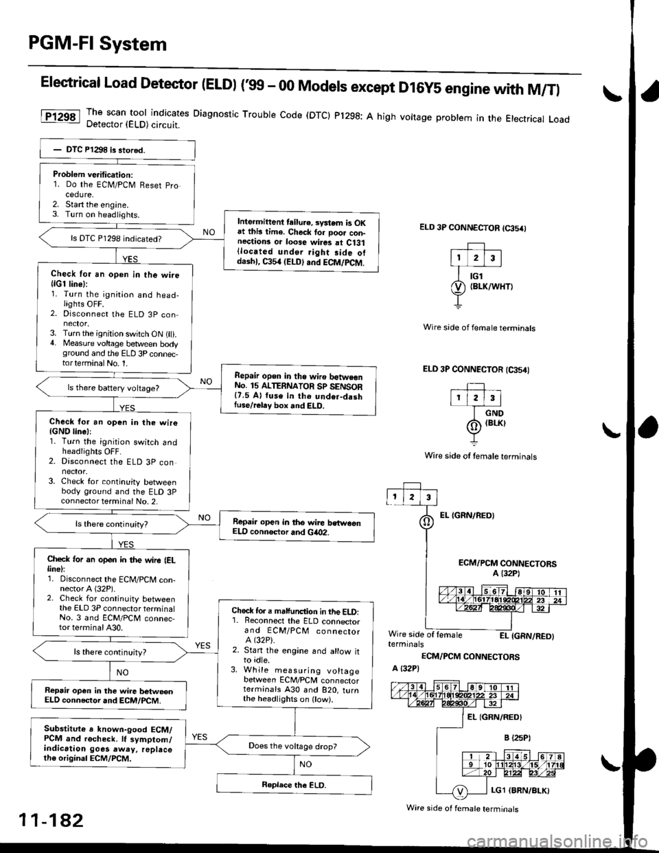
Elestrical Load Detector (ELDI ('99 - 00 Models except D16y5 engine with M/Tl
The scan tool indicates Diagnostic Trouble code (DTCI Pl298: A high vottage problem in the Etectrical LoadDetector (ELD) circuit.
ELD 3P CONNECTOR (65/0
EL {GRN/REOI
Wire side of fernale terminals
ELD 3P CONNECTOR (CA54I
TIr l2l3l
I crvo
(o) (BrKr
Y
Wire side of lemale terminals
ECM/PCM CONNECTORSA (32P1
Wire side of lemaleEI- IGRN/RED)terminals
ECM/PCM CONNECTORS
A {32P)
Problem ve.itication:1. Do the ECN4/PCM Reset pro
cedure.2. Start the engine.3- Turn on headiights.Inte.mittent teilu.e, svstem is OKat this lime. Chock for Door con-nections or loose wires at Ci31{located under Jight side otdaihl, C354 (ELD) and ECM/PCM.
ls DTC P1298 indicated?
Check for an open in the wire{lG1 line}:1. Turn the ignition and head-lights OFF.2. Disconnect the ELD 3P con
3. Turn the ignition switch ON (ll).4. Measure voltage between bodyground and the ELD 3P connec-torterminalNo. 1.
Repair opon in tho wiro batwe€nNo. 15 ALTERNATOR Sp SENSOR{7.5 A} fuse in th6 undor-dashIuse/reley box and ELD.
ls there battery voltage?
Check for an open in the wiro{GND linel:1. Turn the ignition switch andheadlights OFF.2. Disconnect the ELD 3P connector.3. Check for continuity betweenbody ground and the ELD 3Pconnector terminal No. 2,
Repair open in the wire bstwoenELD connsctor and Gia02.
Check ,or an open in the wire IELlinel:1. Disconnect the ECM/PCM con-nector A (32P).2. Check for continuity betweenthe ELD 3P connector terminalNo. 3 and ECM/PCM connec-tor terminal A30.
Chock fo. a malfunction in the ELD:'1. Reconnect the ELD connectorand ECM/PCM connectorA (32P).
2. Stan the engine and allow itto idle.3. While measuring voltagebetween ECM/PCM connectorterminals A30 and B2O, turnthe headlighrs on ow).
ls there continuity?
Repsir op€n in the wire betweenELD connector and ECM/PCM.
Substitute a known-good ECM/PCM and recheck. lf symptom/indication goes away. replacelh6 original ECM/PCM.
Does the vokage drop?
Wire side of f€male terminals
11-182
Page 459 of 2189
ldle Control System
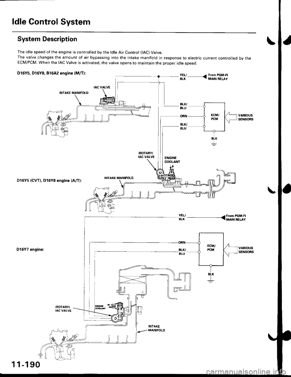
System Description
The idle speed ot the engine is controlled by the ldle Air Control (lAC) Valve.The valve changes the amount of air bypassing into the intake manifold in response to electric current controlled bv theECM/PCM. When the IAC Valve is activated, the valve opens lo maintain the proper idle speed.
D16Y5, D16Y8, Br6A2 engine (M/T):
(ROTARYItac vat-vEEI{GINEcooLAI{T
VARIOUSsEI{SORS
VARIOUSSENSORS
INTAKE MANIFOTDDl6Ys {CVTl, D16Y8 engine lA/T):
D16Y7 engine:
{ROTABY)
;iy--, - ---
11-190