inhibitor HONDA CIVIC 1996 6.G Owner's Manual
[x] Cancel search | Manufacturer: HONDA, Model Year: 1996, Model line: CIVIC, Model: HONDA CIVIC 1996 6.GPages: 2189, PDF Size: 69.39 MB
Page 915 of 2189
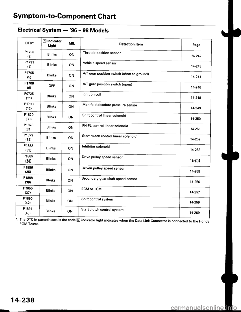
Symptom-to-Component Chart
Electrical System -'96 - 98 Models
*: The DTC in parentheses is the code @ indicator light indicates when the Data Link Connector is connected to the HondaPGM Tester.
DTC*O Indicator
LightMILDetection ltemPage
P1790
(3)BlinksONThrottle position sensor14-242
P179'l
(4)BlinksONVehicle speed sensor14-243
P1705
(5)BlinksONAy'T gear position switch (short to groundl't 4-244
P1706
(6)OFFONA/T gear position switch {open)14-246
P0725
(11)BlinksONlgnition coil14-248
P1793
112lBlinksONManifold absolute pressure sensor14-249
P 1870(30)BlinksONShift control linear solenoid14-250
P'1873
(311BlinksONPH-PL control linear solenoid14-25'l
P1879(32)BlinksONStart clutch control linear sotenoid14-252
P1882BlinksONInhibitor solenoid14-253
P1885
(34)BlinksONDrive pulley speed sensor1l-Zb4
P1886(35)BlinksONDriven pulley speed sensor14-255
P1888
(36)BlinksONSecondary gear shaft speed sensor14-256
T to55
(37)BlinksONECM or TCM14-257
P1890
l42lBlinksONShift control system14-259
P1891
(43)BlinksONStart clutch control svstem14-260
14-23a
Page 917 of 2189
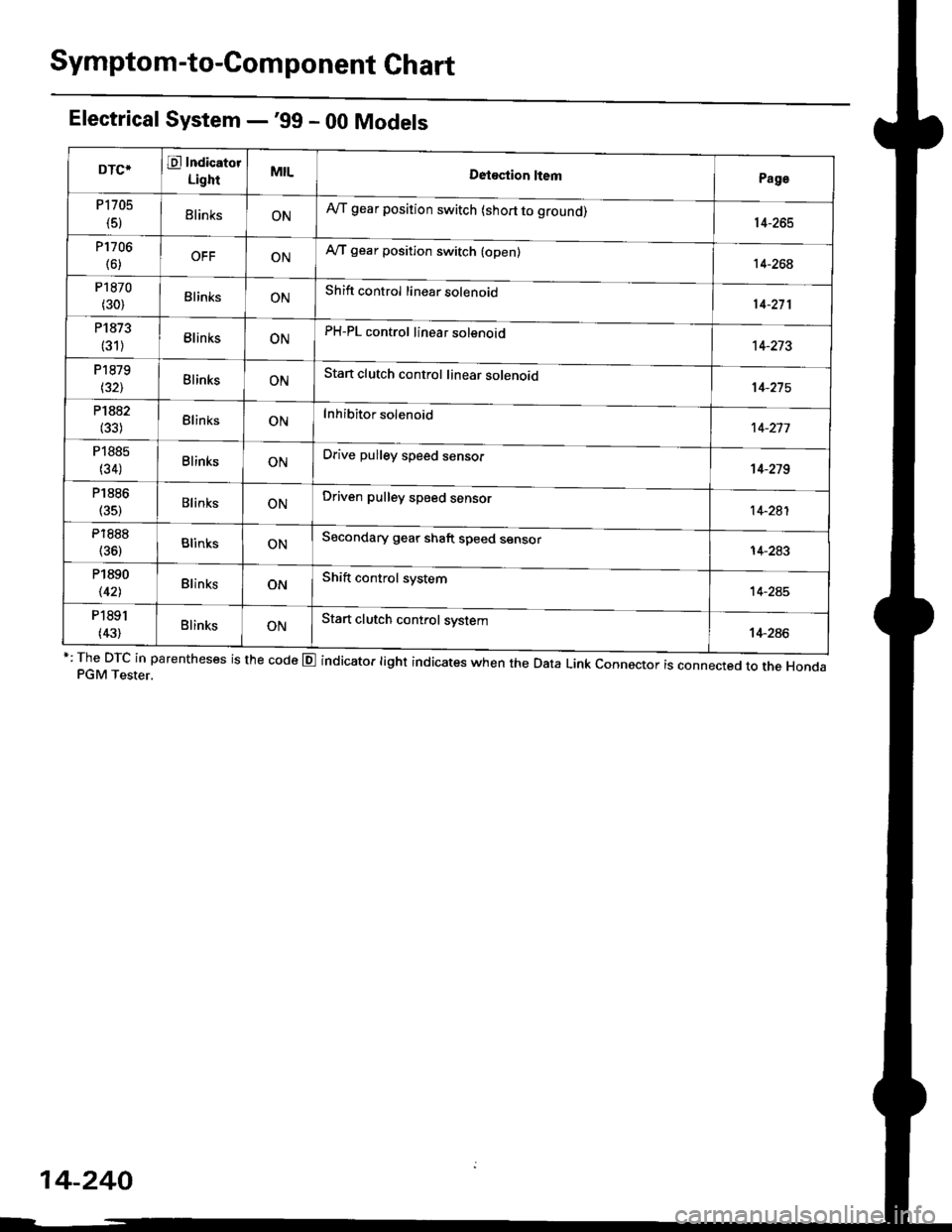
Symptom-to-Com ponent Chart
Electrical System -'99 - 00 Models
r: The DTc in parentheses is the code E indicator light indicates when the Data Link connector is connected to the HondaPGM Tester.
DTCTE Indicatot
LighrMILDetostion ltemPage
P1705
(5)ElinksONA,/T gear position switch (short to grouno,14-265
P1706
(6)OFFONA"/T gear position switch (open)14-26€
P1870
(30)BlinksONShift control linear solenoid14-271
P1873
(31)BlinksONPH-PL control linear solenoid14-213
P1879
t32lBlinksONStan clutch control linear solenoid
Inhibitor solenoid
14-215
P1882(33)BlinksON't 4-277
P1885
(34)BlinksONDrive pulley speed sensol't 4-279
P1886
(35)BlinksONDriven pulley speed sensor14-281
P1888
(36)BlinksONSecondary gear shaft speed sensor
Shift control system
14-283
P1890
\421BlinksON14-245
P1891
(43)BlinksONStart clutch control system14-286
14-240
Page 930 of 2189
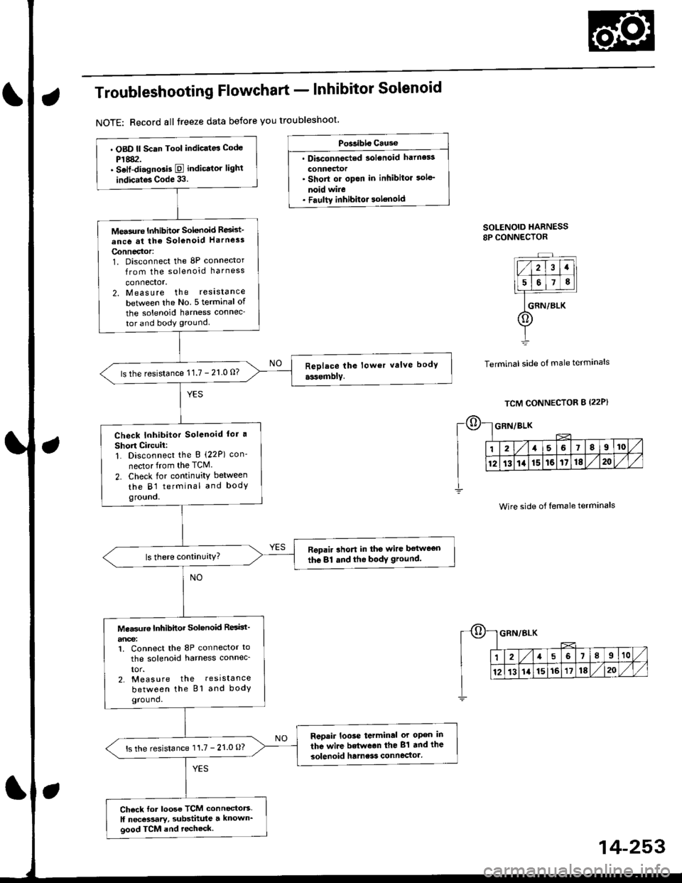
Troubleshooting Flowchart - Inhibitor Solenoid
NOTE: Record all treeze data betore you troubleshoot
Po$ibls Cause
. Dbconnected solenoid hatness
connedor' Short or opon in inhibitor sole'
noid wire. Faultv inhibitor solenoid
SOLENOID HARNESS8P CONNECTOR
Terminal side of male terminals
. OBD ll Scan Tool indic.td Code
P1882.. Selt-di.gnGis E indicator lighl
indic.tos Code 33.
Mea3ure Inhibhor Solenoid Resid-
ance at the sol€noid Harness
Connector:1. Disconnect the 8P connector
from the solenoid harness
connector.2. Measure the reslstance
betlveen the No 5 terminal of
the solenoid harness connec-
tor and body ground.
ls the resistance 11.7 - 21 0 0?
Check Inhibitor Solenoid lor a
Short Circuii:1. Disconnect the B (22P) con-
nector from the TCM.
2. Check for continuity between
the B1 terminal and bodygro!no.
Repair rhort in the wire ltetwegn
the 81 dnd the bodY ground.
Mea$rr€ Inhibitor Solenoid ResBt'
anoe:1. Connect the 8P connector to
the solenoid harness connec_
IOr.2. Measure the resistance
between the Bl and bodyground.
Reoair loose terminal or open in
the wire betwean the 81 and the
solenoid hame3s connector'ls the resistance 11.7 - 21.0 O?
Ch6ck for loose TCM connectors.
ll necessary, substhule a known_good TCM and techeck.
Wire side of female terminals
14-253
Page 954 of 2189
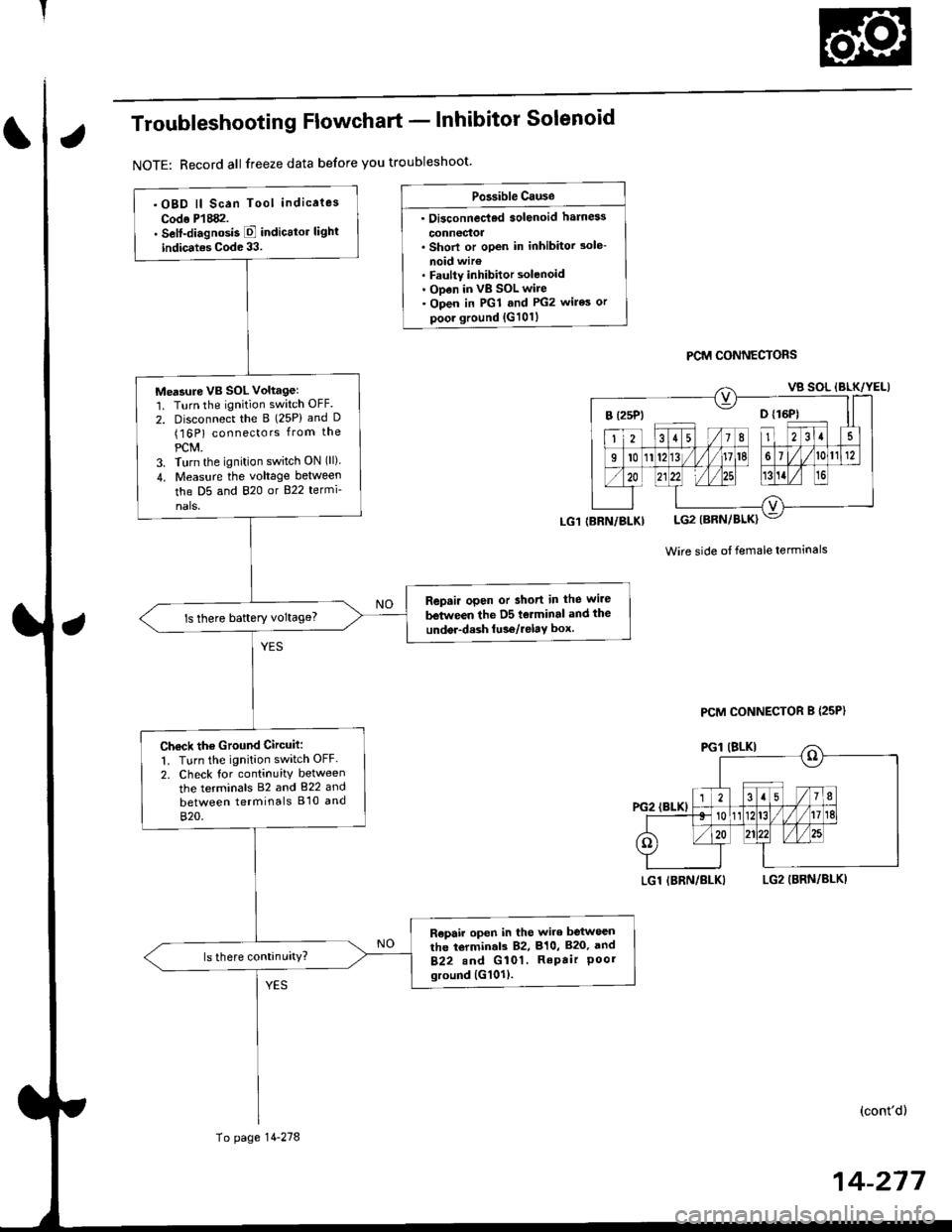
Troubleshooting Flowchart - lnhibitor Solenoid
NOTE: Record all freeze data before you troubleshoot'
Po3sible Cause
. Oi3connec'ted solenoid harn6s
connectoa. Shorl or open in inhibitor 3ole-
noid wir€. Faulty inhibitor solenoid. ODen in vB SOL wire. Open in PGl and PG2 wires or
poor ground {G101}
PCM CONNECTORS
Wire side ot female terminals
LGl IBRN/BLKILG2 (BRN/BLKI
(cont'd)
14-217
.OBD ll Scan Tool indicaies
Codo P'l882.. Self-diagnosis E indicttor light
indic.tes Code 33.
Me'sure VB SOL voltagel'1. Turn the ignition switch OFF.
2. Disconnect the B (25P) and D(16P) connectors from the
PCM.3. Turn the ignition switch ON (ll)
4. Measu.e the voltage between
the D5 and 820 or B22 termi-
nals.
Repair open or short in the wire
between the D5 tolminal and the
undor-dash lu36/relay box.ls there baftery voltage?
Ch€ck the Ground Circuit:
1. Turn the ignition switch OFF.
2. Check tor continuity between
the terminals 82 and 822 and
between terminals B'10 and
820.
R€pair open in the wire between
the torminal3 82, 810, B20, and
B22.nd G 101. RePair Poorground {G101).
(BRN/BLKI
To page 14-278
PCM CONNECTOR B {25P}
Page 955 of 2189
Electrical Troubleshooting ('99 - 00 Models)
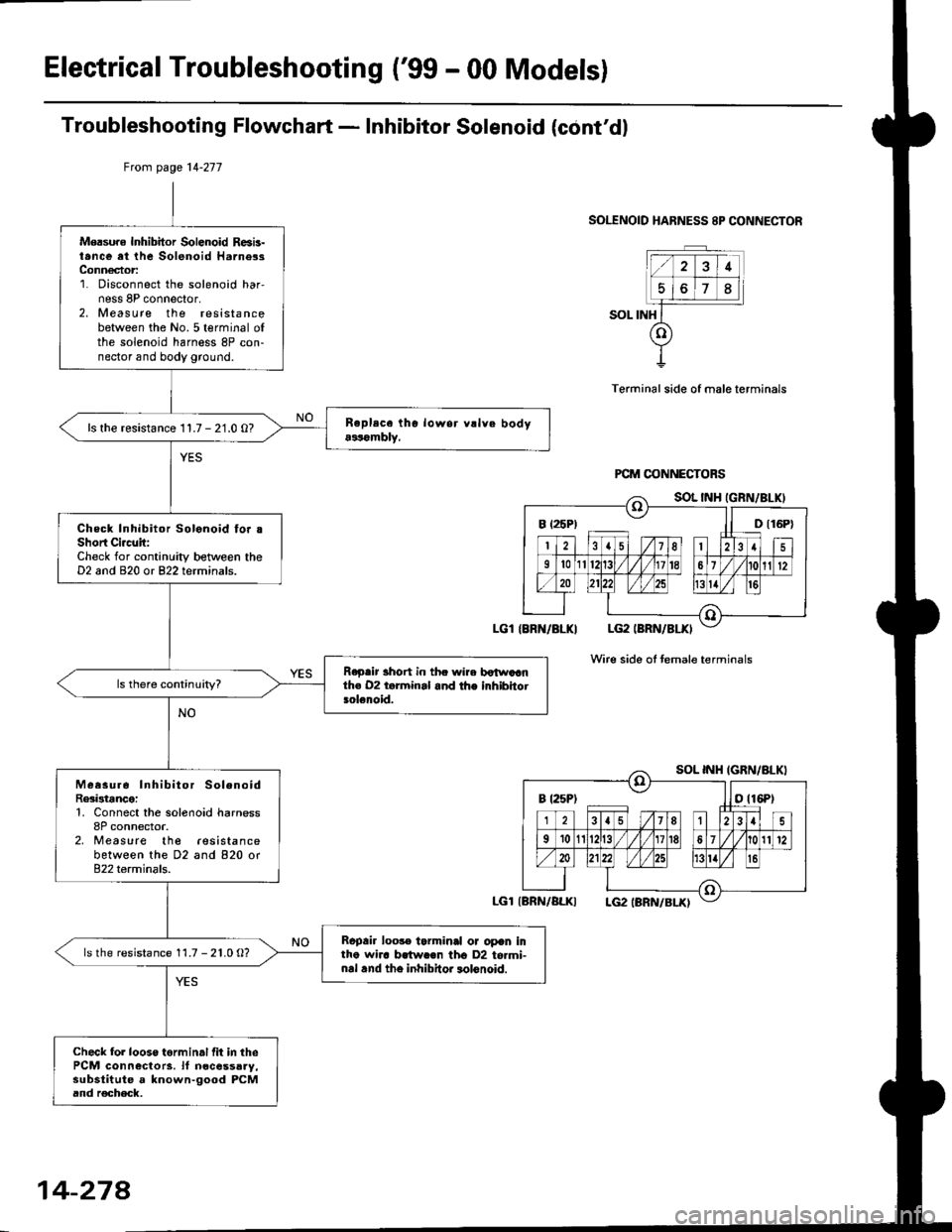
Troubleshooting Flowchart - Inhibitor Solenoid (cont'dl
SOLENOID HARNESS 8P CONNECTOR
SOL INH
Terminal side of male terminals
Wire side oI temale terminals
Mersure Inhibitor Solenoid R6b-t.nce at the Solenoid Harne3sConn€ctor:1. Disconnect the solenoid har,ness 8P connector,2. Measure the resistancebetween the No.5 terminal ofthe solenoid harness 8P con-nector and body ground.
ls the resistance 11.7 - 21.0 O?
Check Inhibitor Solonoid fo. .Short Ci.c!it:Check for continuity between theD2 and 820 or 822 terminals.
R.p.ir 3hort in thc wire botwaanth€ 02 t.rminal and the inhibhotsolenoid.
Measur6 Inhibitor SolenoidRe3istance:1, Connect the solenoid harness8P connector.2, Measure the lesistancebetween the D2 and 820 or822 terminals.
Rcpair loo3. tarminal or opan intho wha brtw.€n tho D2 to.mi-nal .nd tho inhibitor lolonoid.
ls the resistance 11.7 - 21.0 O?
Check fol looso torminal fit in thePCM connectors. lf n€cessaay,substitute a known-good PCMand r€check.
Ftom page 14-277
LGl IBRN/BLKI
LGl{BRN/ALKI
B t25P) ll D t16P)
B t25Pt otl6Pt
14-274
Page 968 of 2189
Linear Solenoids/lnhibitor Solenoid
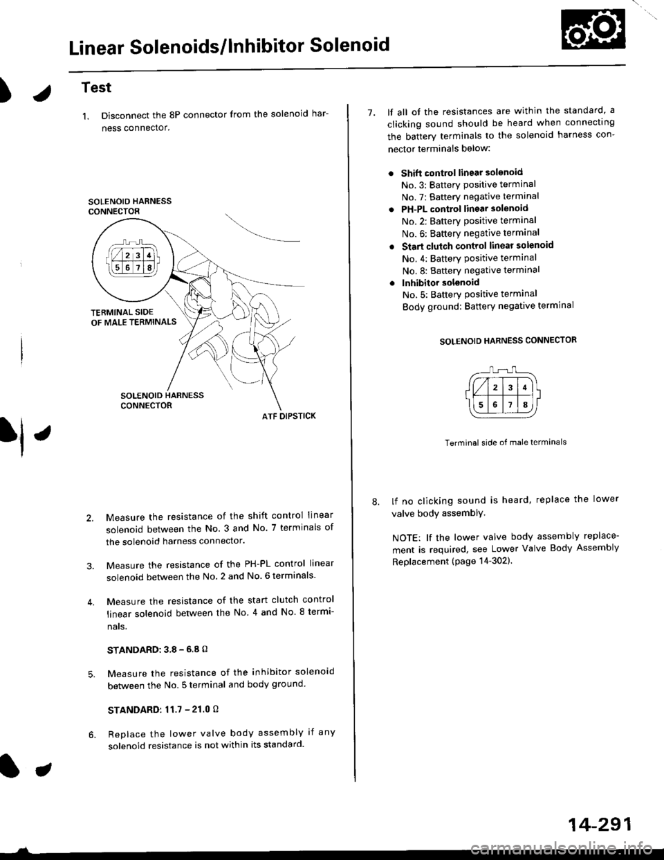
)Test
1. Disconnect the 8P connector from the solenoid har-
ness connector.
SOLENOID HARNESSCONNECTOR
ATF OIPSTICK
Measure the resistance of the shift control linear
solenoid between the No. 3 and No. 7 terminals of
the solenoid harness connector.
Measure the resistance of the PH-PL control linear
solenoid between the No. 2 and No. 6 terminals
Measure the resistance of the start clutch control
linear solenoid between the No 4 and No. 8 termi-
nats,
STANDARD:38-6.8O
Measure the resistance of the inhibitor solenoid
between the No. 5 terminal and body ground
STANDARD:11.7 - 21.0 O
Replace the lower valve body assembly if any
solenoid resistance is not within its standard.
7. lf all ot the resistances are within the standard, a
clicking sound should be heard when connectrng
the batterv terminals to the solenoid harness con-
nector terminals below:
Shift control linear solsnoid
No.3: Batterv Positive terminal
No. 7: Battery negative terminal
PH-PL control linear solenoid
No.2: Batterv oositive terminal
No. 6: Baftery negative terminal
Start clutch control linear solenoid
No. 4: Battery Positive terminal
No.8: Battery negative terminal
lnhibitor solsnoid
No,5: Batterv Positive terminal
Body ground: Battery negative termrnal
SOLENOID HARNESS CONNECTOR
Terminal side of male terminals
lf no clicking sound is heard, replace the lower
valve body assemblY,
NOTE: lf the lower valve body assembly replace-
ment is required, see Lower Valve Body Assembly
Replacement (page 14-302).
14-291
Page 972 of 2189
t.
rl,
fl,
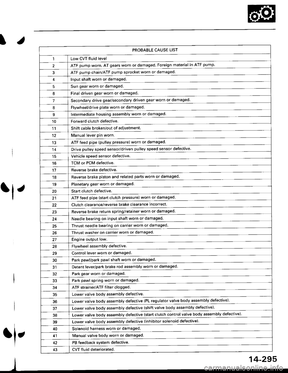
PROBABLE CAUSE LIST
Low CVT fluid level
ATF pump worn. AT gears worn or damaged. Foreign material in ATF pump.
ATF pump chain/ATF pump sprocket worn or damaged.
Input shaft worn or damaged.
Sun gear worn or damaged.
Final driven oear worn or damaqed,
Secondary drive gear/secondary driven gear worn or damaged-
5
6
1
8Flywheel/drive plate worn or damaged.
Intermediate housing assembly worn or damaged.9
'10Forward clutch defective.
Shift cable broken/out of adiustment.
M"nu"t t"uffi
ATF feed pipe (pulley pressure) worn or damaged.
Vchiclc speed sensor defective.
TCM or PCM defective.
Reverse brake detective.
1'�r
't2
13
14
16
'11
'18
1qPlanetary gear worn or damaged.
Sta rt clutch defective.
ATF feed pipe (start clutch pressure) worn or damaged
20
t't
Clutch clearance/reverse brake clearance incorrect.
23Reverse brake return spring/retainer worn or damaged
24Needle bearing on input shaft worn or damaged.
25Thrust needle bearing on carrier worn or damaged.
Thrust washer on carrier worn or damaged.
Enoine outout low.------------------------
Flvwhcel assemblv defective.
Control lever worn or damaged.
Park pawl/park pawl shaft worn or damaged
Detent lever/park brake rod assembly worn or damaged
27
29
30
32Park gear worn or damaged.
Park pawl spring worn or damaged.
ATF strainer/ATF filter clogged.
Lower valve body assembly defective.
Lower valve bodv assemblv defective (PL regulator valve body assembly defective)'
33
34
50
Lower valve bodv assembly defective (shift valve body assembly defective).
Lower valve bodv assemblv defective (start clutch control valve body assembly defective)'
39Lower valve bodv assemblv defective {inhibitor solenoid defective}
40Solenoid harness worn or damaged.
Manual valve body worn or damaged.
PB feedback system defective.
CVT fluid deteriorated.
41
43
14-295
Page 997 of 2189
Manual Valve Body
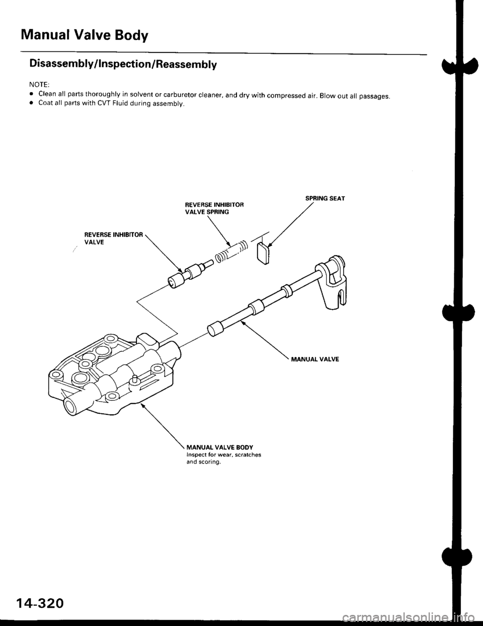
Disassembly/lnspection/Reassembly
NOTE:
. Clean all parts thoroughly in solvent or carburetor cleaner, and dry with compressed air. Elow out all passages.. Coat all parts with CVT Fluid during assembly.
SPRING SEATREVERSE INHIBITORVALVE SPRING
REVERSE INHIBITORVALVE
MANUAL VALVE
MANUAL VALVE BODYInspect for wear, scratchesand sconng,
14-320