PCM HONDA CIVIC 1996 6.G Service Manual
[x] Cancel search | Manufacturer: HONDA, Model Year: 1996, Model line: CIVIC, Model: HONDA CIVIC 1996 6.GPages: 2189, PDF Size: 69.39 MB
Page 382 of 2189
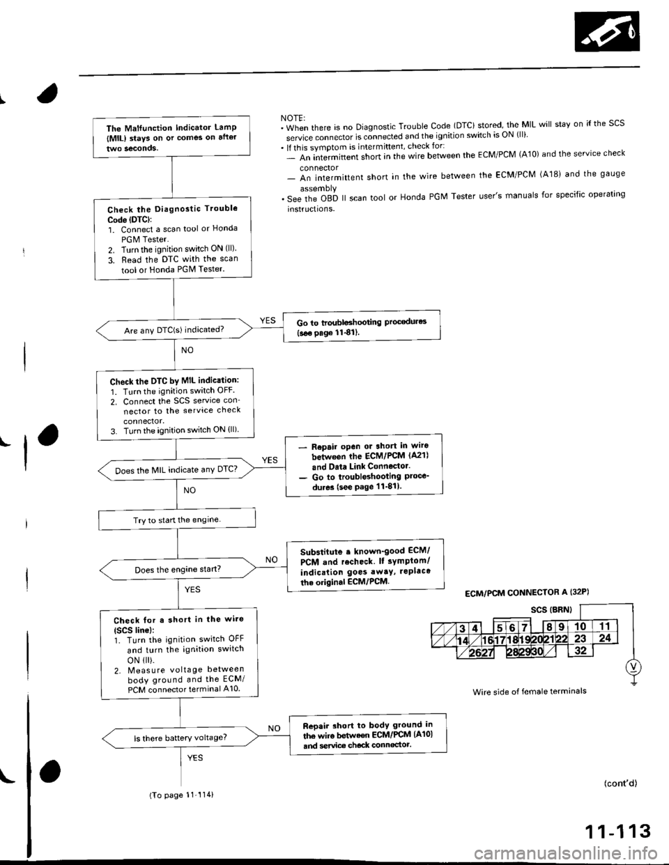
NOTE:"in-"n tf'"r" is no Diagnostic Trouble Code (DTCi stored, the MIL will stav on ;{ the scs
service connector is connected and the ignition switch is ON (ll)
. lf this symptom is intermittent, check for:- An intermittent short in the wire between the ECM/PCM (A10) and the service check
connector- An intermittent short in the wire between the ECM/PCM (A181 and the gauge
. s"" it'" Oab ll scan tool or Honda PGM Tester user's manuals for specific operating
instructions.
'l
ECM/PCM CONNECTOR A I32P)
Wire side of female terminals
The Malfunction Indicator LamP
lMlL) staYs on or comes on after
Check the Diagnostic Trouble
Code (DTC):
1. Connect a scan tool or Honcla
PGM Tester.
2. Turn the ignition switch ON (ll)
3. Read the DTC with the scan
tool or Honda PGM Tester.
Go to troubloshooting Proc€dures(see page 1141).Are any DTC(S) indicated?
check the DTC by MIL indic.tion:
1. Turn the ignition switch OFF
2. Connect the SCS service con_
nector to the service check
3. Turn the ignition switch ON (ll)
Repair open or 3hort in wiro
between ihe ECM/PCM (A21)
and Data Link Connector.
Go to troubleshooting Ploce_du.es (see page 11-811.
Does the MIL indicate anY DTC?
Try to start the engine
Substitute . known-good ECM/
PCM and recheck lt sYmptom/
indication goes awaY, rePlaca
th. original ECM,/PCM.
Check for a short in the wi.e(Scs line):1. Turn the ignition switch OFF
and turn the ignition switch
oN 1 ).2- Meas u re voltage between
body ground and the ECM/
PCM connector terminal A10
Reoair short to body ground in
the wiro bstwaen ECM/PCM (A101
and service ch€ck connoctot.ls there battery voltage?
(To page 11-'114)
(cont'd)
1 1-1 13
Page 383 of 2189
PGM-FI System
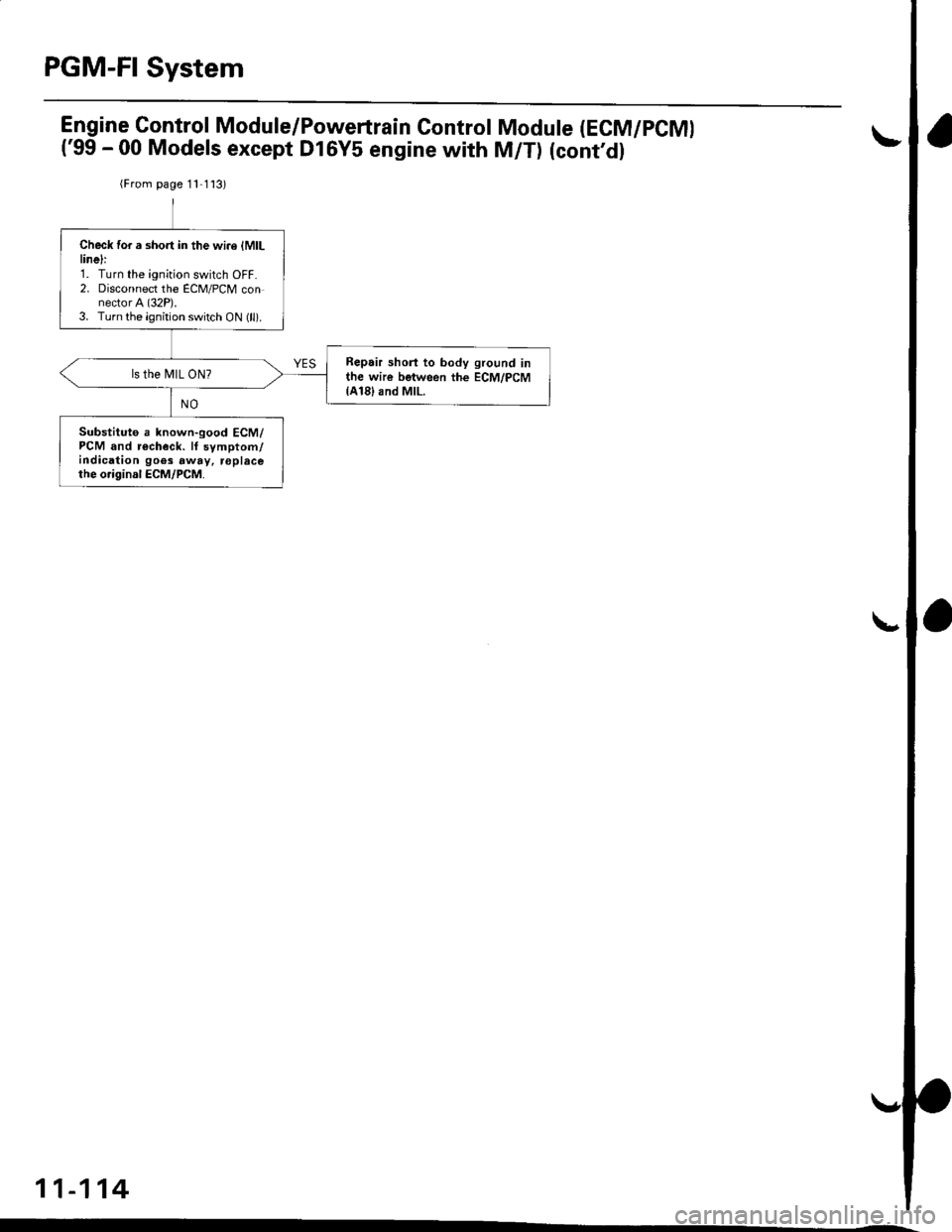
Engine Gontrol Module/Powertrain Control
('99 - 00 Models except Dl6Y5 engine with
Module (ECM/PCMI
M/T) (cont'dl
{From page 11 1 l3)
Check for a short in the wi.e lMlLlinelr1. Turn the ignition switch OFF.2. Disconnect the ECM/PCM connector A (32P).3. Turn the ignition switch ON (ll).
Repair shorl to body ground inthe wire between the ECM/PCM{A18}and MlL.
ls the MIL ON?
Substituto a known-good ECM/PCM and r€check. lf symptom/indication goes away, roplacethe o.iginal ECM/PCM.
11-114
Page 384 of 2189
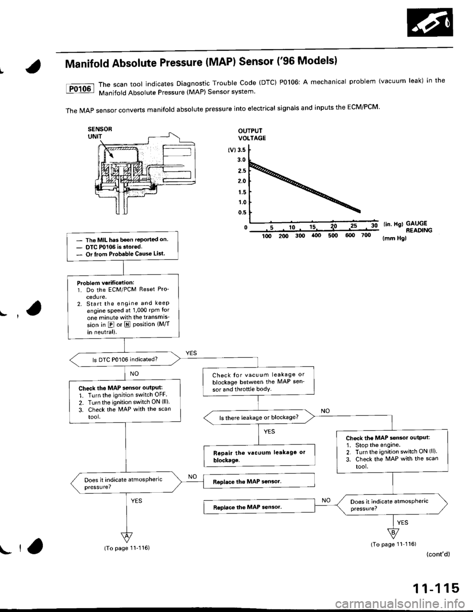
Manifold Absolute Pressure (MAP) Sensor ('96 Models)
The scan tool indicates Diagnostic Trouble Code (DTC) P0106: A mechanical problem (vacuum leak) in the
Manifold Absolute Pressure (MAP) Sensor system'
TheMAPsensorconvertsmanifoIdabsoIutepressureintoeiectricaIsigna|sandinpUtstheEcM/PcM'
OUTPUTVOLTAGE
(v13.5
3.0
2.5
2.0
1.5
1.0
0.5
0lin. Hgl GAUGE
- The MIL has been reported on- OTC P0106 is storod.- Or from Ptobable Cause Lisl.
Problom verificetion:1. Do the ECM/PCM Reset Pro-
cedure.2. Start the engine and keep
engine speed at 1,000 rpm for
one minute with the transmis'
sion in @ or I Position {Mff
in neutral).
ls DTC P0106 indicated?
Check tor vacuum leakage or
blockage between the MAP sen'
sor and throftle bodyCheck the MAP sensor outPut:
1. Turn the ignition switch OFF
2. Turn the ignition switch ON (ll).
3. Check the MAP with the scan
tool.ls there leakage or blockage?
Chock the MAP s€nsol output:
1. Stop the engane.2. Turn the ignition switch ON (ll).
3. Check the MAP with the scan
tool.
READING300(mm Hgl
(To page 11 116)
{cont'd)ll,(To page 11-116)
1 1-1 15
Page 385 of 2189
PGM-FI System
(From page 11-115i{From page 11-115)
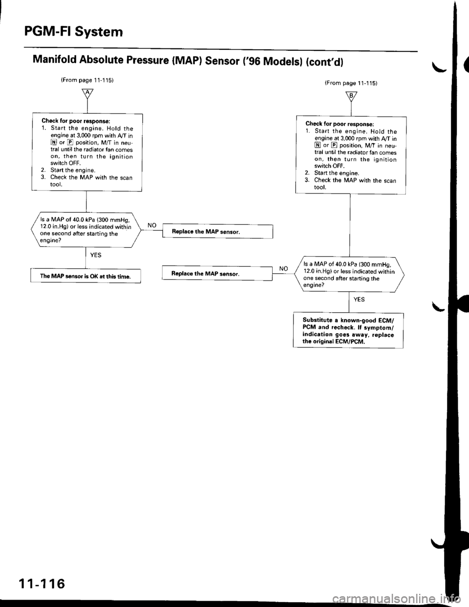
Chock to. poor response:1. Start the engine. Hold theengine at 3,000 rpm with M inE or E position, M/T in neutral untilthe radiator tan comeson, then turn the ignitionswitch OFF.2. Start the engine.3. Check the MAP with the scantool.
ls a N4AP ot 40.0 kPa {300 mmHg,12.0 in.Hg) or less indicated withinone second after staning theengine?
The MAP sensor is OK st this time.
Check lor poor response:1. Start the engine. Hold theengine at 3,000 rpm with M inE or E position, M/T in neu-tral until the radiator fan comeson, then turn the ignitionswitch OFF.2. Start the engine.3. Check the MAP with the scantool.
ls a MAP of 40.0 kPa (300 mmHg,12.0 in.Hg) or less indicated withinone second after starting theengine?
Substitute a known-good ECM/PCM and rechock. lt symptom/indication go6s .way. .6plrceth€ original ECM/PCM.
Manifold Absolute Pressure (MAP) Sensor ('96 Modelsl (cont'dl
11-116
Page 386 of 2189
Manifold Absolute Pressure {MAP} Sensor
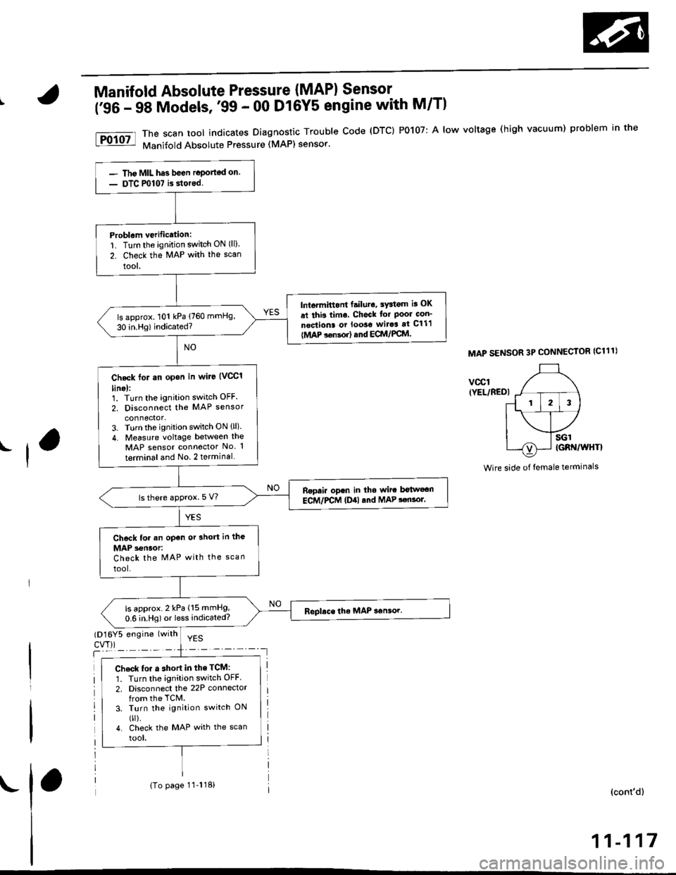
('96 - 98 Models,'99 - 00 D16Y5 engine with M/T)
I
The scan tool indicates Diagnostic Trouble Code (DTC) PO107: A low voltage (high vacuum) problem in the
Manifold Absolute Pressure (MAP) sensor.
MAP SENSOR 3P CONNECTOR (C111)
vccr(YEL/BEDI
Wire side of female terminals
(D16Y5 engine (with
cw))T
YES
(cont'd)
11-117
Tho MIL has been roport€d on.
DTC P0107 is storod.
Problam verification:1. Turn the ignition switch ON (ll).
2. Check the MAP with the scan
lool.
lntormittont failuro, sYatgm ia OK
al thb timo. Chock lor Pool con_
noqtiona or looso wirca at C111
{MAP !6nsor) ond ECM/PCM.
ls approx. 101 kPa (760 mmHg,
30 in.Hg) indicated?
Chock for an opon in wiJe (VCCI
lino):1. Turn the ignition switch OFF.
2. Disconnect the MAP sensor
3. Turn the ignition switch ON (ll).
4. Measure voltage between the
MAP sensor connector No l
terminal and No 2 terminal
Ropair open in tho wit b€twocn
ECM/PCM (Dill tnd MAP !enso].ls there approx. 5 V?
Check for .n open or ahort in the
MAP 3€naor:Check the MAP with the scan
tool.
ls approx. 2 kPa (15 mmHg,
0.6 in.Hg) or less indicated?
Chsck to. a short in the TCM:
1. Turn the ignition switch OFF.
2. Disconnect the 22P connectorfrom the TCM.3. Turn the ignition switch ON
0r).4. check the MAP with the scan
tool.
(To page 11-118)
Page 387 of 2189
PGM-FI System
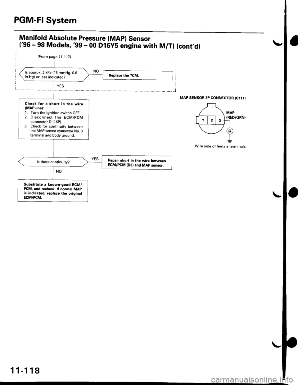
(From page 11-117)
ls approx. 2 kPa ('15 mmHg, 0.6in.Hg) or less indicated?
Check for a short in ihe wire{MAP line)l1. Turn the ignition switch OFF.2. Disco n nect the ECM/pCMconnector D (16P).
3. Check for continuity betweenthe MAP sensor connector No.3terminal and body ground.
R6pair lhort in tha wire b€twaenECM/PCM {D3l .nd MAP !6ru0r.
Substitute a known-good ECM/PCM..nd recheck. normal MAPis indiceted, .eplsce lhe originalECM/PCM,
Manifold Absolute Pressure (MAp) Sensor('96 - 98 Models,'99 - 00 D16Y5 engine with M/Tl (cont,d)
MAP SENSOR 3P CONNECTOR IC1l1I
MAP(RED/GRNI
Wire side of femate;rminats
11-118
Page 388 of 2189
|'Manifold Absolute Pressure (MAP) Sensor
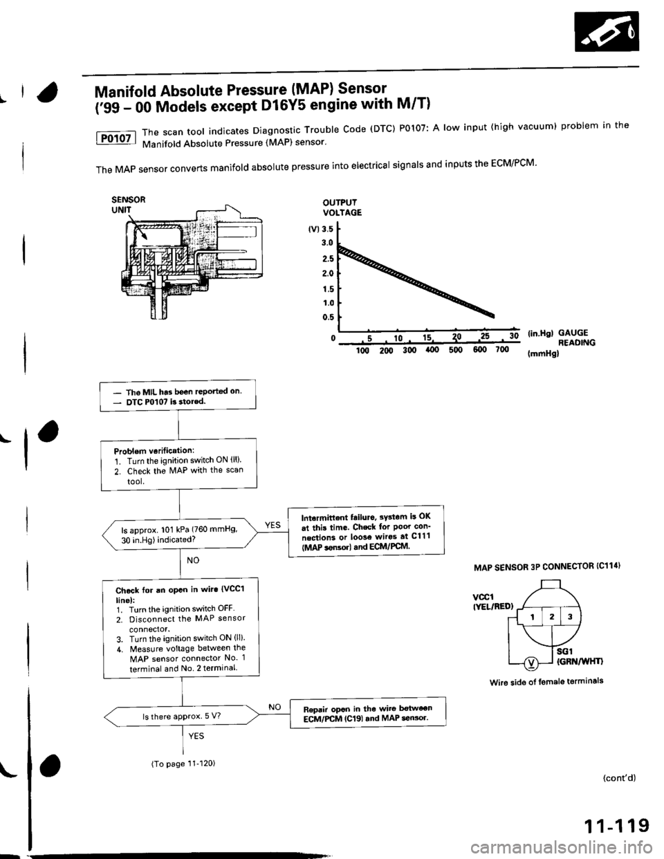
(;gg - OO Models except Dl6Y5 engine with M/T)
The scan tool indicates Diagnostrc Trouble Code (DTC) PO1O7: A low input (high vacuuml problem in the
Manifold Absolute Pressure (MAP) sensor'
The MAp sensor converts manifold absolute pressure into electrical signals and inputs the ECM/PCM'
OUTPUTVOLTAGE
lvl3.5
3.0
2.5
2.0
1.5
1.0
0.5
0(in.Hgl GAUGEREAOING(mmHgllq, 2oo 3q, (x, 5q) 6q) 700
MAP SENSOR 3P CONNECTOR IC114)
vccltYEL/RED)
Wire sido of fomalg tormin6ls
.-l
- The MIL h'3 been reported on- OTC P0107 b stor€d.
Problem verilication:
1. Turn the ignition switch ON {ll)
2. check the N4AP with the scan
tool.
lntermittent failuro, 3Ystom is OK
at this time. Ch€ck for Poor con'
nection3 or loose wiros at C111
IMAP sonsorl and ECM/PCM.
ls approx. 101 kPa (760 mmHg,
30 in.Hg)indicated?
Ch.ck for an opcn in wit. {vCC1
linel:1. Turn the ignition switch OFF
2. Disconnect the MAP sensor
connector.3. Turn the ignition switch ON (ll).
4. Measure voltage between the
MAP sensor connector No. 1
terminal and No 2 terminal
Repair opsn in the wirg botween
ECM/PCM (C19) rnd MAP seGor.ls there approx. 5 V?
(To page 11-120)
{cont'd)
1 1-1 19
Page 389 of 2189
PGM-FI System
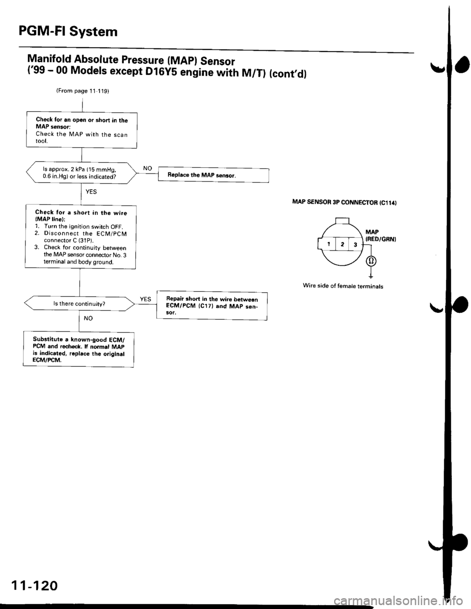
Manifold Absolute Pressure (MApl Sensor('99 - 00 Models except Dl6yS engine with M/T) (cont,dl
MAP SENSOn 3P CONNECTOB tcllilt
MAP(RED/GRNI
Wire side of female terminals
(From page 11 119)
Check for an open or shon in theMAP s€nsor:Check the MAP with the scantool.
ls approx. 2 kPa (15 mmHg,0.6 in.Hg) or less indicated?
Check tor a sho.t in lhe wire{MAP line):1. Turn the ignition switch OFF.2. Discon n ect the ECN4/pCN4connector C (31P).3. Check for continuity betweenthe MAP sensor connector No. 3terminal and body ground.
Repair short in the wire betweenECM/PCM {Cl7} and MAp s€n-sor.
Substitute a known-good ECM/PCM and rech6ck. lf no.mal MApis indicated, replace the o.iginalECM/rcM.
11-120
Page 390 of 2189
!Manifold Absolute Pressure (MAPI Sensor -
i;idlga lil;dels,'99 - 00 Dl6Y5 ensine with M/T)
ll
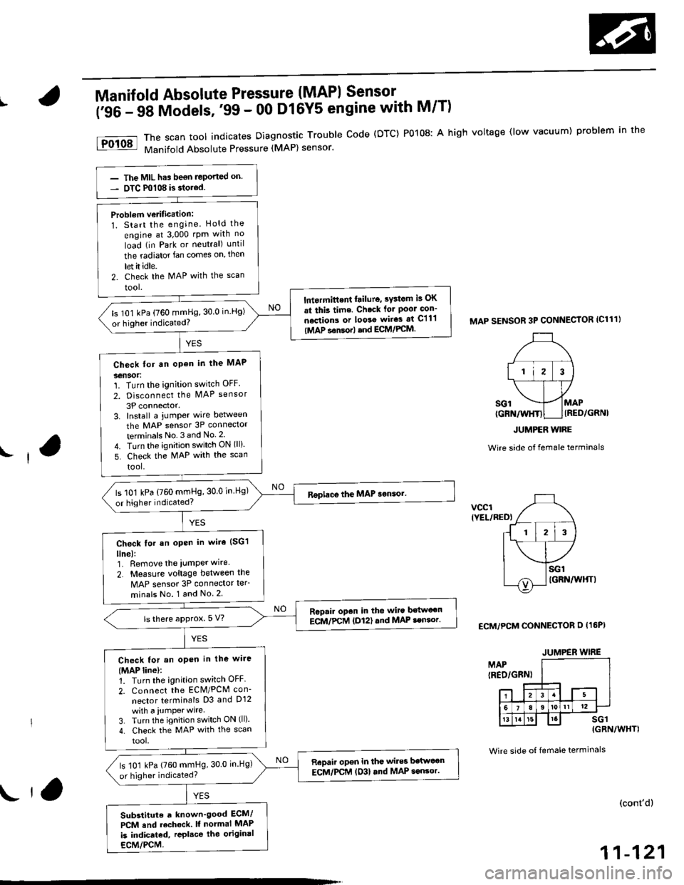
The scan tool indicates Diagnostrc Trouble code (DTC) Po108: A high voltage (low vacuum) problem in the
Manifold Absolute Pressure (MAP) sensor.
MAP SENSOR 3P CONNECTOR ICl11}
MAPIRED/GRNI
JUMPER WIRE
Wire side ol female terminals
vcclIYEL/RED)
ECM/PCM CONNECTOR D (16PI
MAP(RED/GRN)
sG1(GRN/WHT)
Wire side of female terminals
(cont'd)
11-121
The MIL has been reported on
OTC m108 is stolod.
Problem vetitication:
1. Start the engine. Hold the
engine at 3,000 rPm with no
load (in Park or neutral) until
the radiator fan comes on, then
let it idle.
2. Check the MAP with the scan
tool.
lntormittent lailure, sFtom k OK
.t thb time. Chock lor Poor con'
nections or loorg wires at Cll'l
|MAP sensorl snd ECM/PCM.
ls 101 kPa (760 mmHg,30 0 in.Hg)
or higher indicated?
Check tor an open in the MAP
36nSOt:1. Turn the ignition switch OFF
2. Disconnect the MAP sensor
3P connector.3. Install a jumper wire betlveen
the MAP sensor 3P connector
terminals No 3and No 2.
4. Turn the ignition switch ON (ll).
5. Check the MAP with the scan
tool.
ls 101 kPa (760 mmHg, 30 0 in.Hg)
or higher indicated?
Check for an open in wire (SG1
line):1. Remove the iumper wire.
2. Measure voltage between the
MAP sensor 3P connector te.
minals No. 1 and No 2
Rapai. open in the wito batwoen
ECM/PCM (D12) .nd MAP !en.or.ls there approx. 5 V?
Check for an oPon in the wiie
(MAP linel:1. Turn the ignition switch OFF.
2. Connect the ECM/PCM con-
nector terminals D3 and D12
with a iumPer wire.
3. Turn the ignition switch ON (ll).
4. Check the MAP with the scan
tool.
Repair opon in the wiles bstlt oon
ECM/PCM (D3l and MAP 3oGor.ls 101 kPa (760 mmHg, 30 0 in.Hg)
or higher indicated?
Substituto a known'good ECM/
PCM and rochock. ll normal MAP
is indicated, replace tho original
ECM/PCM.
JUMPER WIRE
lr,
Page 391 of 2189
PGM-FI System
Manifold Absolute Pressure (MAPI Sensor
11-122
('99 - 00 Models except D16YS engine with M/T) (contd)
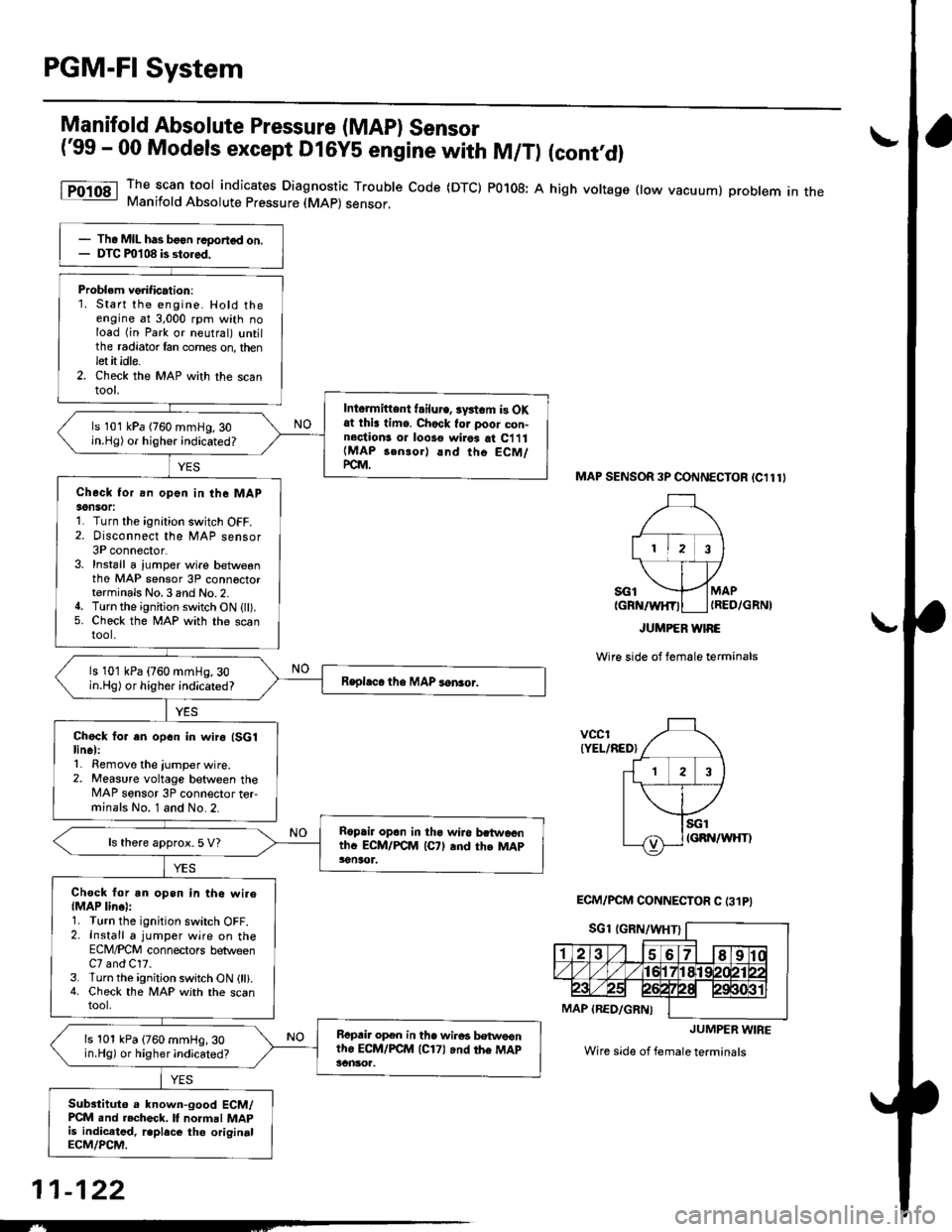
The scan tool indicates Diagnostic Trouble Code (DTC) P0108: A high voltage flow vacuum) problem in theManifold Absolute Pfessure (MAp) sensor,
MAP SENSOR 3P CONNECTOR (C111I
MAPIRED/GRNI
Wire side of female terminals
vcclIYEL/RED)
ECM/PCM CONNECTOR C (31PI
JUMPER WIRE
Wire side of female terminals
Tho MIL has boon rcDortod on.DTC ml 08 b stolod.
Problem verification:'1. Start the engine. Hold theengine at 3,000 rpm with noload (in Park or neutral) untilthe radiator fan comes on, thenlet it idle.2. Check the MAP with the scantoot,
Intormittent f.ilu.e, rystom is OXat thi! time. Chock tor poor con-n6ction3 or looso wirea at C111(MAP 3en.or) and tho ECM/PC-M.
ls 101 kPa (760 mmHg.30in.Hg) or higher indicated?
Check for an open in the MAPaon5('r:1. Turn the ignalion switch OFF.2. Disconnect the MAP sensor3P connector.3. Install a jumper wire betwesnthe MAP sensor 3P conn6ctorterminals No.3 and No.2.4. Turn the ignition switch ON {ll).5. Check the MAP with the scantool.
ls 101 kPa (760 mmHg, 30in.Hg) or higher indicated?
Check fo. an opcn in wiro (SGlline):1. Removo the jumper wire.2. Measure voltage between theMAP sonsor 3P connector terminals No. 1 and No.2.
Roprir opon in tha wiJo bctwoenthc ECM/FCM (C7l rnd the MApsonln t.
ls there approx. 5 V?
Chsck for an open in tho wi.e{MAP lino}:1. Turn the ignition switch OFF.2. Install a jumper wire on theECM/PCM connectors betweenC7 and C17.3. Turn the ignition switch ON (ll).4. Check the MAP with the scantool,
Repair op€n in the wir6a bstwoontho ECM/FCM (C171 and rh6 MApscnltoa.
ls 101 kPa (760 mmHg, 30in.Hg) or higher indicated?
Substituto a known-good ECM/PCM and rechcck, It normal MAPis indiceted. r.place tho originalECM/PCM.
JUMPER WIRE
--