1 page HONDA CIVIC 1996 6.G Workshop Manual
[x] Cancel search | Manufacturer: HONDA, Model Year: 1996, Model line: CIVIC, Model: HONDA CIVIC 1996 6.GPages: 2189, PDF Size: 69.39 MB
Page 1306 of 2189
Front Seat
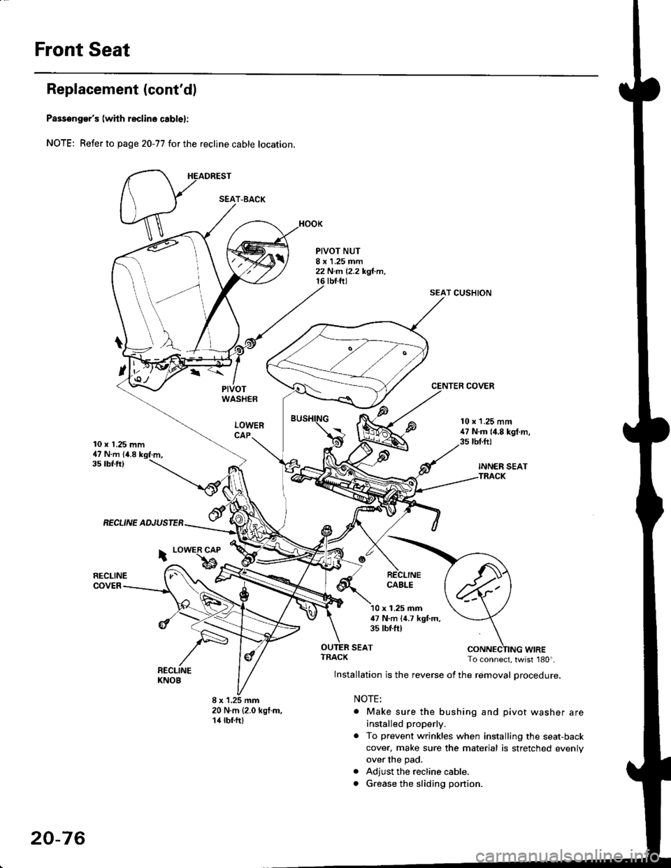
Replacement (cont'd)
Passenger's (with reclino cablel:
NOTE; Refer to page 20-77 for the recline cable location.
HEADREST
PIVOTWASHER
LOWERCAP
PIVOT NUT8 x 1.25 mm22 N.m 12,2 kgl.m,tbt.ftt
SEAT CUSHION
CENTER COVER
10 x 1,25 mm47 N.m (4.8 kgf.m,
10 x 1.25 mm47 N.m {4.8 kgf.m,3s tbt.ft)
INNER SEATTRACK
35 tbf.ftl
RECLINE ADJUSTEB
RECLINECOVER
i LowER CAP
bRECLINECABLE
x 1.25 mm47 N'm (4.7 kgf.m,35 tbtftl
SEAT
8 x 1.25 mm20 N.m {2.0 kgf.m,14 rbf.ft)
ruf, To connect, twist 180'.
lnstallation is the reverse of the removal procedure.
NOTE:
. Make sure the bushing and pivot washer are
installed properly.
. To prevent wrinkles when installing the seat-back
cover, make sure the material is stretched evenly
over the pad.
. Adjust the recline cable.
. G.ease the sliding ponion.
SEAT-BACK
20-76
Page 1308 of 2189
Front Seat
2.
1.
3.
CUSHIONCOVER
cover all the
remove the
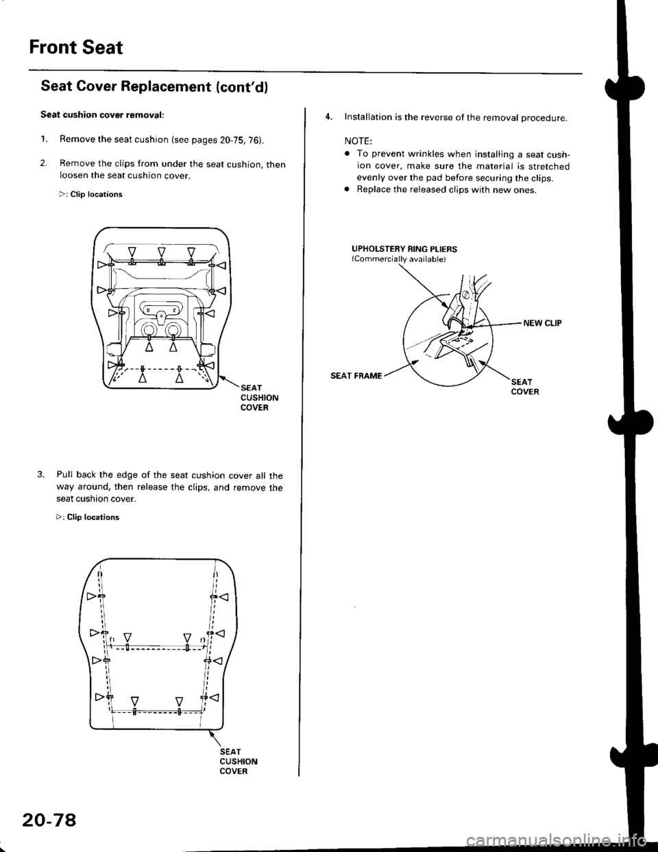
Seat Cover Replacement (cont'd)
Seat cushion cover removal:
Remove the seat cushion {see pages 20,75,76).
Remove the clips from under the seat cushion, thenloosen the seat cushion cover.
>: Clip locataons
Pull back lhe edge of the seat cushion
way around, then release the clips, and
seat cushaon cover.
>: Clip locations
SEATCUSHIONCOVER
1-. v v vl
20-7A
4. Installation is the reverse of the removal procedure.
NOTE:
. To prevent wrinkles when installing a seat cush-ion cover, make sure the material is stretched
evenly over the pad before securing the clips.. Replace the released clips with new ones.
UPHOLSTERY RING PLIERS
NEW CLIP
SEAT FRAME
Page 1309 of 2189
![HONDA CIVIC 1996 6.G Workshop Manual Rear Seat
Removal
NOTE: Take care not to scratch the seat covers and body.
4D:
>: Bolt locationsl_):Hook locations,2
b,,***-,,.1*
D>
] >mr
;iffiP-"*piii::#r-,-, @t,V . se-ri-cusxo" [-6*
v-
2u
2u
S HONDA CIVIC 1996 6.G Workshop Manual Rear Seat
Removal
NOTE: Take care not to scratch the seat covers and body.
4D:
>: Bolt locationsl_):Hook locations,2
b,,***-,,.1*
D>
] >mr
;iffiP-"*piii::#r-,-, @t,V . se-ri-cusxo" [-6*
v-
2u
2u
S](/img/13/6068/w960_6068-1308.png)
Rear Seat
Removal
NOTE: Take care not to scratch the seat covers and body.
4D:
>: Bolt locationsl_):Hook locations,2
b,,***-,,.1*
D>'
] >mr
;iffiP-"*'piii::#r-,'-, @t,V . se-ri-cusxo" [-6*
v-
2u
2u
SEAT CUSHION
SEAT-BACK
Pivot boll conslruction:
SLITS
lnstallation is the reverse of the removal procedure
PIVOT BOLT ERACKET8 x 1.25 mm22 N m (2.2 kgf m, 16lbtftl
Apply liquid thread lock
NOTE:
. Before attaching the seat-back and seat cushion, make sure there are no twists or kinks in the rear seat belts and
center belt.
. When installing the seat cushion, slip the seat belt buckles through the slits in the seat cushron'
. Make sure the seat-back locks securely.
. lf necessary, adiusr the seat-back latch (see page 20-82) and seat-back (cont'd)
c>,1
6x1.omm l1Q- e "r.o--s.a ru.- tr.o rer-. I s.i N.- ir.o lgr.,i7.2 lbf.ft) ) E 7.2 'tJrftl
:- '/
>: Clip locations, 14
"@rz, \
EEES/
_ _ot /
RIGHT SEATSIDE EOLSTER
CENTEBPIVOTBRACKET
20-79
Page 1310 of 2189
Rear Seat
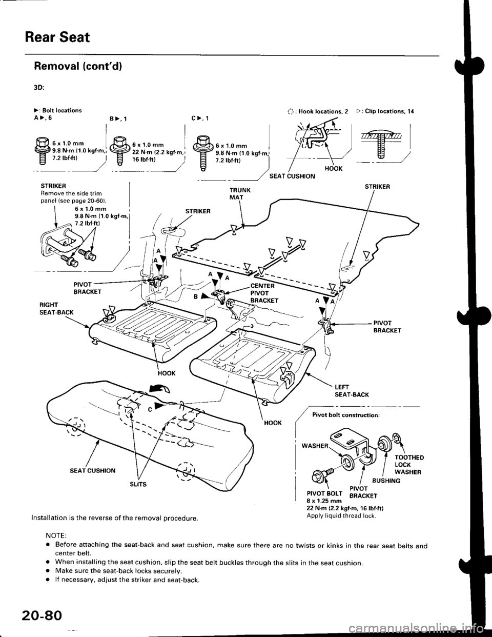
Removal (cont'dl
3D:
>: Bolt locationsA>,6
':^2
STRIKERRemove the side t.impanel (see page 20-60).
c>,1
STBIKER
,.:) : Hook locations, 2 >: Clip locations, 14
SEAT CUSHION
STRIKER
6x1.0mm9.8 N.m (1.0 kgI.m,7.2 tbf.ft)
V
RIGHTSEAT-BACK
Pivot bolt constiuction:
TOOTHEOLOCKWASHER
BUSHING
PIVOT
Installation is the reverse of the removal procedure.
NOTE:
Ptvor BoLT BRACKETI x 1.25 mm22 N.m {2.2 kgl.m. 16 lbf.ft)Apply liquid thread lock.
. Beiore anaching the seat-back and seat cushion, make sure there are no twists or kinks in the rear seat belts andcenter belt.
. When installing the seat cushion, slip the seat belt buckles through the slits in the seat cushion.. Make sure the seat-back locks securely.
. lf necessary, adjust the striker and seat-back.
20-ao
6xr.omm I9.8 N.m (1.0 ksf.h,i
@,
EE)qr ,/
6x1omm I22 N.m {2.2 kgf.m,l,"rrr,n2
PIVOTBRACKET
LEFTSEAT.BACK
tt
A
CENTERPIVOT
\---.---
6x1.0mm
BRACKET
B>, 1
e
I
tr
-l:/*- -"HOOK
Page 1311 of 2189
2Dt
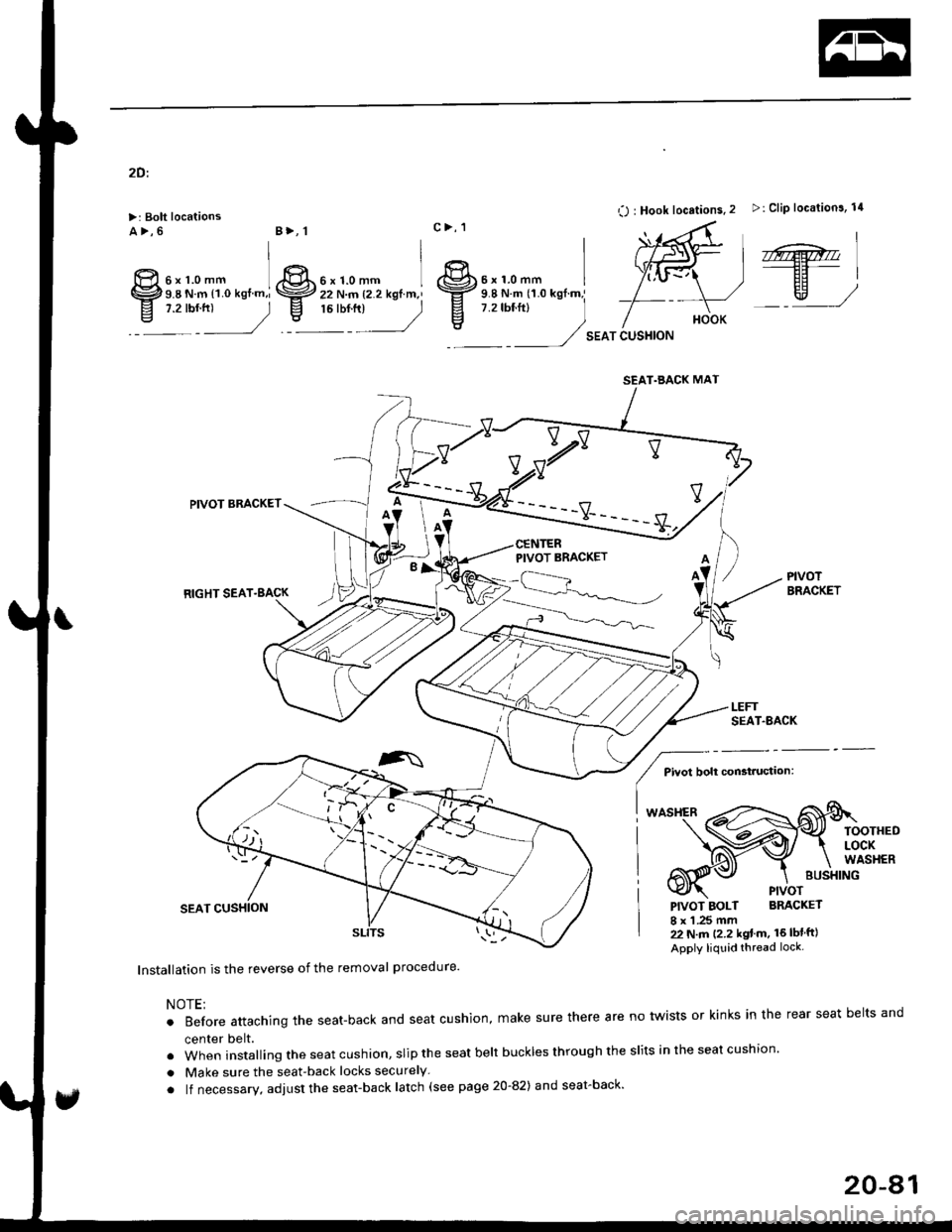
>: Bolt locationsa>,6
O : Hook locations. 2 >: Clip location3, 14
SEAT CUSHION
,r@.''----EF-|
EH)w,/
PIVOTBRACKET
BUSXING
PIVOT
PIVOT BOLT BRACKET
I x 1 .25 mm22 N.m (2.2 kgt m. 16lblft)
Apply liquid thread lock.
lnstallation is the reverse of the removal procedure'
NOTE;
.Beforeattachingtheseat-backandseatcushion,makesuretherearenotwistsorkinksintherearseatbe|tsand
center belt.
.wheninsta||ingtheseatcushion,sliptheseatbe|tbucklesthroughthes|itsintheseatcushion.
. Make sure the seat-back locks securely
. lf necessary, adjust the seat-back latch (see page 20-82) and seat-back'
6xr.omm ]9.8 N.m l1.O kgf.m,i,:r:2
B>, 1
ffi
IgIt
c>, 1
6xr.omm I 8r.'r.o-- r22 N.m {2.2 kgtm,' \ffz s.e N.m tr.o *gf.m,'
,r:r",
_) E
7.2rbf.ftl
)
vv
PIVOT BRACKET
RIGHT SEAT.BACK
PIVOT BRACKET
Pivot bolt constauctaon:
TOOTHEDLOCKWASHER
SEAT.BACK MAT
,^
20-41
Page 1312 of 2189
Rear Seat
Seat-back Latch Replacement
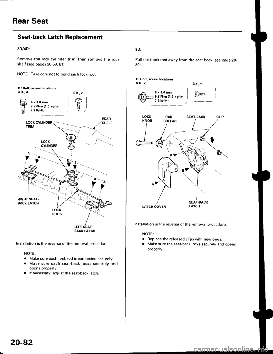
2Dl4Dl
Remove the lock cylinder trim, then remove the rear
shelf (see pages 20 59, 61).
NOTE: Take care not to bend each lock rod.
>: Boh, screw locationsA>,4
6x1.0mm9.8 N.m (1.0 kgt.m,7.2 rbf.ftl
LOCK CYLINOERTRIM
.i.-::
LOCKRODS
LEFT SEAT-EACK I-ATCH
Installation is the reverse of the removal procedure.
NOTE:
. Make sure each lock rod is connected securely.. [/ake sure each seat-back locks securely and
opens properly.
. lf necessary, adjust the seat-back latch.
B >,2
/+j
V
LOCKCYLINDER
20-8�2
3D:
Pull the trunk mat away from the seat'back (see page 20-
80).
>: Boll, screw locationsa>,2
6x1.0mm9.8 N.m (1.0 kgf.m,7.2 tbl.ft)
B>, 1
@
LATCH COVEB
Installation is the reverse ofthe removal procedure.
NOTE:
. Replace the released clips with new ones.. lvlake sure the seat-back locks securely and opensproperly.
SEAT"BACK
Page 1313 of 2189
Seat Cover Replacement
CAUTION: Put on gloves to protact your hands,
NOTE| Take care not to tear the seams or damage the seat
covers.
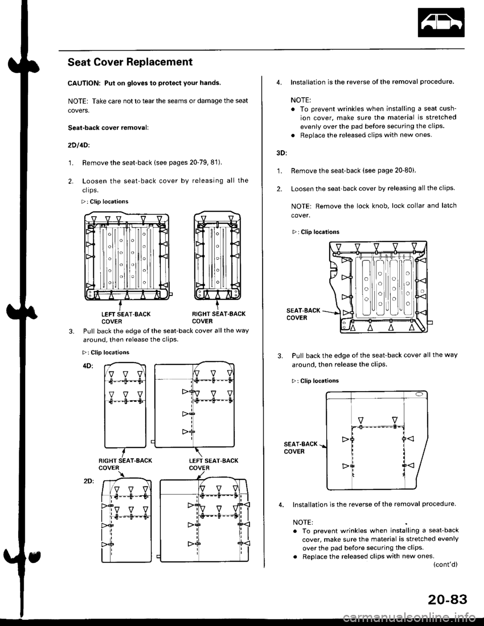
Seat-back cover removal:
2D l4Dl
1. Remove the seat-back (see pages 20-79,8'1).
2. Loosen the seat-back cover by releasing all the
clrps.
>: Clip locations
LEFT SEAT-BACKCOVERRIGHT SEAT.EACKCOVER
3.Pull back the edge of the seat-back cover all the way
around. then release the clios.
>: Clip locations
RIGHT SEAT.BACK
1.
2.
4. Installation is the reverse of the removal procedure.
NOTE:
. To prevent wrinkles when installlng a seat cush-
ion cover. make sure the material is stretched
evenly over the pad before securing the clips.
. Replace the released clips with new ones
3D:
Remove the seat-back (see page 20-80).
Loosen the seat-back cover by releasing all the clips.
NOTE: Remove the lock knob, lock collar and latch
cover.
>: Clip locations
SEAT-BACKCOVER
3. Pull back the edge of the seat-back cover all the way
around, then release the cliPs.
>: Clip locations
SEAT.BACKCOVER
Installation is the reverse of the removal procedure.
NOTE:
. To prevent wrinkles when installing a seat-back
cover, make sure the material is stretched evenly
over the pad before securing the clips.
. Replace the released clips with new ones.(cont'd)
o
o
o
o
o
o
o
o
20-a3
Page 1314 of 2189
Rear Seat
Seat Cover Replacement (cont'dl
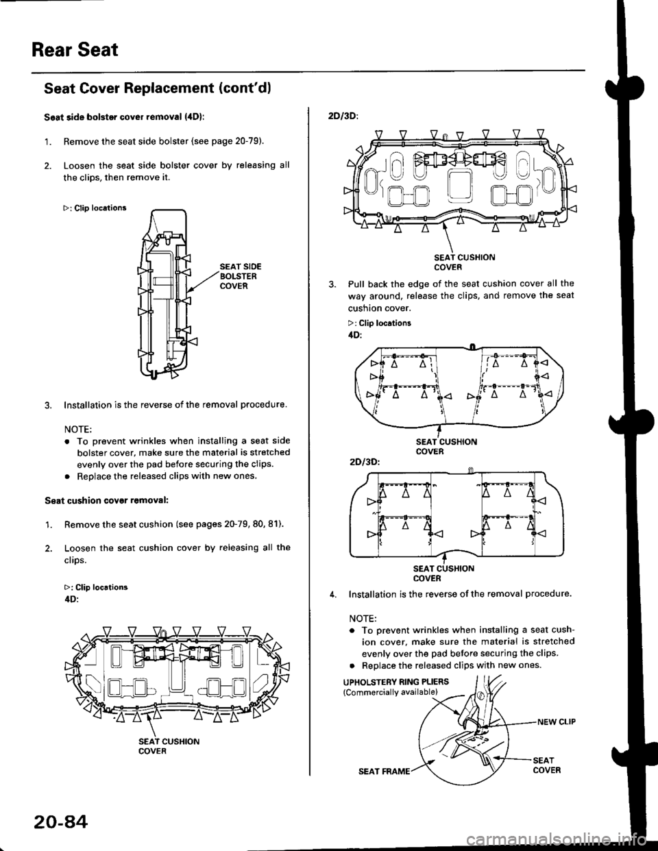
Seat side bolstor cover removal {,lDl
1. Remove the seat side bolster (see page 20-79).
2. Loosen the seat side bolster cover by releasing all
the clios, then remove it.
>: Clip locations
SEAT SIDEBOLSTERCOVER
3. Installation is the reverse of the removal procedure.
NOTE:
. To prevent wrinkles when installing a seat side
bolster cover, make sure the material is stretched
evenly over the pad before securing the clips.
. Reolace the released cliDs with new ones,
S€at cushion covgr r6moval:
1. Remove the seat cushion (see pages 20-79, 80, 81).
2. Loosen the seat cushion cover by releasing all the
clips.
>: Clip locrtion3
4D:
- -I ./al--lt___)l ) ( .)Ll!!l^t!!l 1",
COVER
20-a4
SEAT FRAME
NEW CLIP
2DI3D:.
SEAT CUSXIONCOVER
Pull back the edge of the seat cushion cover all the
way around, release the clips, and remove the seat
cusnton cover.
>: Clip location3
/tD:
4. Installation is the reverse ofthe removal procedure.
NOTE:
. To prevent wrinkles when installing a seat cush-
ion cover. make sure the material is stretched
evenly over the pad before securing the clips.
a Replace the released clips with new ones.
UPHOLSTERY RING PLIERS
{Commerciallv available)
a\
------)
t" I FEF4+#€
R-U U m
'J)
,.ofl r_r olJr
2Dl3Dl
COVER
Page 1315 of 2189
Front Seat Belt
Replacement
CAUTION: Check the front seat belts for damage, and
replace them it necessary. Be carolul not to damage
them during removal and installation.
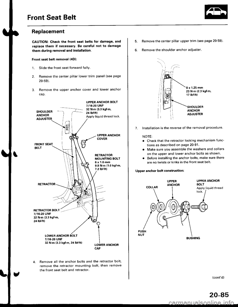
Front seat belt removal (4Dl:
1.Slide the front seat forward fully.
Remove the center pillar lower trim panel (see page
20-59).
Remove the upper anchor cover and lower anchor
cap.
SHOULDERANCHOR
UPPER ANCHOR BOLT7/16-20 UNF32 N.m (3.3 kgit m,24 lbf.ft)Apply liquid thread lock.
2.
3.
FRONT SEATBELT
RETRACTOR
RETRACTORMOUNTING BOLT6x1.0mm9.8Nm(1.0kgf.m.7.2 tbf.ftl
ER ANCHOR
Remove all the anchor bolts and the retractor bolt,
remove the retractor mounting bolt, then remove
the front seat belt and retractor.
1
I
ILOWCAP
7/1&20 UNF32 N.m (3.3 kgl.m.24 rbl.ftl
7/16-20 UNF32 N.m {3.3 kgf.m,24lbf.ft}
6.
8 x 1.25 mm23 N.m {2.3 kgt'm,17 tbf.ft)
ANCHORADJUSTER
7. Installation is the reverse of the removal procedure
NOTE:
. Check that the retractor locking mechanism func-
tions as described on page 20-91.
. Make sure you assemble the washers and collars
on the uDDer and lower anchor bolts as shown.
. Before installing the anchor bolts, make sure there
are no twists or kinks in the front seat belt.
Upper anchor boh construciion:
UPPER ANCHORBOLT
Remove the center pillar upper trim (see page 20-59)
Remove the shoulder anchor adjuster.
UPPER
COLLARApply liquid thread
(cont'd)
20-85
SUSHING
Page 1316 of 2189
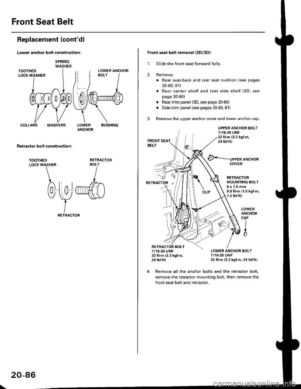
Front Seat Belt
Replacement (cont'dl
Lower anchor bolt construction:
SPRINGWASHER
COLLARSBUSHINGLOWERANCHOB
Retractor bolt construqtion :
TOOTHEDLocK W\HER
)rtnl
tv-
RETRACTORBOLT
I
llo1r",ffi)
\y
-"\s\,/
IRETBACTOF
LOWER ANCHOR
WASHEBS
\
20-86
Front seat belt removal (2Dl3Dl:
1. Sljde the front seat forward fully.
2. Removel
. Rear seat-back and rear seat cushion (see pages
20-80, 81)
. Rear center shelf and rear side shelf (3D. see
page 20'60)
. Rear trim panel (3D, see page 20-60)
. Side trim panel (see pages 20'60,61)
3. Remove the upper anchor cover and lower anchor cap.
UPPER ANCHOR BOLT7/16-20 UNF32 N.m (3.3 kgI.m,24 tbf.ftl
@<-'-.-.-.- ,PPER aNcHoR
RETRACTORMOUNTING BOLT6x1.0mm9.8 N.m (1.0 kgt m,7.2 tbtft)
LOWER ANCHOR BOLT7/16-20 UNF32 N.m (3.3 kgl m, 24lbtft)
LOWEBANCHORCAP
IIto
4. Remove all the anchor bolts and the retractor bolt,
remove the retractor mounting bolt, then remove the
front seat belt and retractor.
RETRACTOR BOLT7/16-20 UNF32 N m 13.3 kgf m,24 tbf.ftl