Connector a HONDA CIVIC 1996 6.G Workshop Manual
[x] Cancel search | Manufacturer: HONDA, Model Year: 1996, Model line: CIVIC, Model: HONDA CIVIC 1996 6.GPages: 2189, PDF Size: 69.39 MB
Page 1667 of 2189
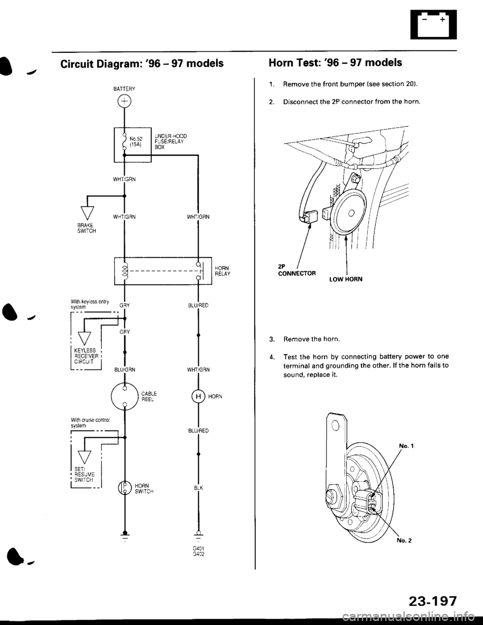
Circuit Diagram: '96 - 97 models
HORNRELAY
WHT/GRN
I(H)HoRN
Y
IBLU/REO
I
I
IBtK
I
t-l
G40lG1A2
BATTERY
l-
23-197
Horn Test: '96 - 97 models
1. Remove the front bumper (see section 20).
2. Disconnect the 2P connector from the horn.
Remove the horn.
Test the horn by connecting battery power to one
terminal and grounding the other, lf the horn fails to
sound, replace it.
3.
LOW HORN
Page 1668 of 2189
![HONDA CIVIC 1996 6.G Workshop Manual Horn
Circuit Diagram: 98 - 00 models
HCRI]tEtAa
BATTEFY
1 98 model: WHT/GRN99 - 00 modelsr BLU/RED
23494
Horn Test: 98 - 00 models
1. Remove the f.ont bumper (see section 20).
2. Disconnect the HONDA CIVIC 1996 6.G Workshop Manual Horn
Circuit Diagram: 98 - 00 models
HCRI]tEtAa
BATTEFY
1 98 model: WHT/GRN99 - 00 modelsr BLU/RED
23494
Horn Test: 98 - 00 models
1. Remove the f.ont bumper (see section 20).
2. Disconnect the](/img/13/6068/w960_6068-1667.png)
Horn
Circuit Diagram: '98 - 00 models
HCRI]tEtA'a
BATTEFY
1 '98 model: WHT/GRN'99 - 00 modelsr BLU/RED
23494
Horn Test: '98 - 00 models
'1. Remove the f.ont bumper (see section 20).
2. Disconnect the 1P connector from the horn.
TERMINAL
Test the horn by connecting
termina I and grounding the
horn fails to sound, replace it.
battery power to the
mou nting bolt. lf the
Page 1669 of 2189
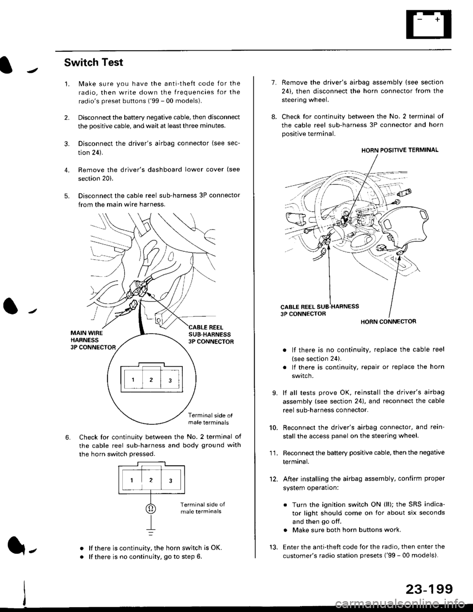
Switch Test
lMake sure you have the anti-theft code for the
radio, then write down the frequencies for the
radio's preset buttons ('99 - 00 models).
Disconnect the battery negative cable, then disconnect
the positive cable, and wait at least three minutes.
Disconnect the driver's airbag connector (see sec-
tion 24).
Remove the driver's dashboard lower cover (see
section 20).
Disconnect the cable reel sub-harness 3P connector
from the main wire harness.
2.
3.
4.
5.
1.
MAIN WIREHARNESS3P CONNECTOR
SUB-HABNESS3P CONNECTOR
REEL
6.
Terminalside olmale terminals
Check for continuity between the No. 2 terminal of
the cable reel sub-harness and body ground with
the horn switch pressed.
alf there is continuity, the horn switch is OK.
lf there is no continuity, go to step 6l-
-\
1.
8.
10.
'I 1.
9.
Remove the driver's airbag assembly (see section
24), then disconnect the horn connector from the
steering wheel.
Check for continuity between the No. 2 terminal of
the cable reel sub-harness 3P connector and horn
positive terminal.
lf there is no continuity, replace the cable reel
(see section 24).
lf there is continuity, repair or replace the horn
swtlcn,
lf all tests prove OK, reinstall the driver's airbag
assembly (see section 24), and reconnect the cable
reel sub-harness connector.
Reconnect the driver's airbag connector, and rein-
stall the access panel on the steering wheel.
Reconnect the battery positive cable, then the negative
termtnar.
After installing the airbag assembly, confirm proper
system operation:
12.
Turn the ignition switch ON (ll); the SRS indica-
tor light should come on for about six seconds
and then go off.
Make sure both horn buttons work.
13. Enter the anti-theft code for the radio, then enter the
customer's radio station presets ('99 - 00 models).
HORN CONNECTOR
23-199
Page 1675 of 2189
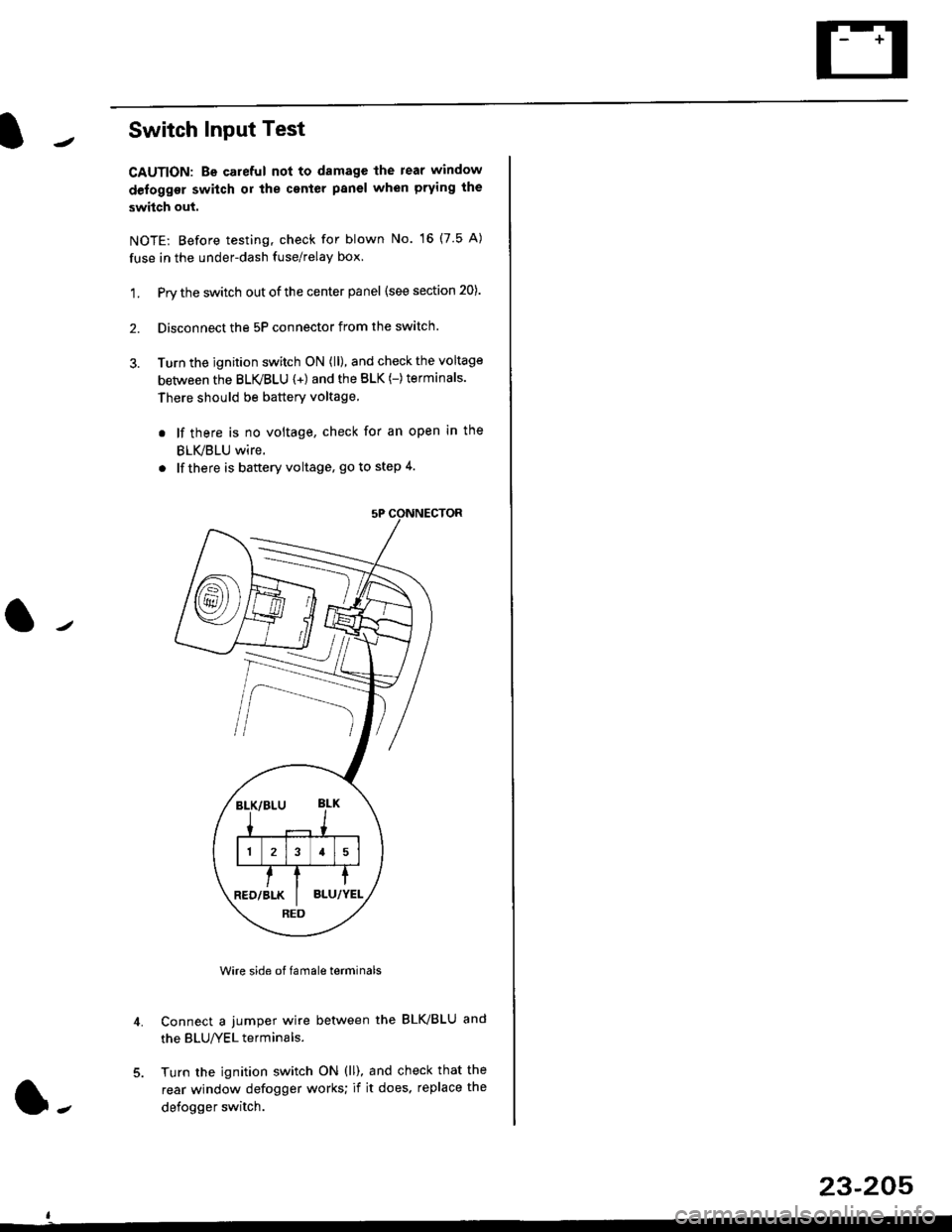
Switch Input Test
CAUTION: Be careful not to damagc the rear window
defogger switch or the center panel when prying the
switch out.
NOTE: Before testing, check for blown No. 16 (7.5 A)
fuse in the under-dash fuse/relay box,
1. Pry the switch out of the center panel (see section 20).
2. Disconnect the 5P connector from the switch.
3. Turn the jgnition switch ON (ll), and check the voltage
between the BLVBLU {+) and the BLK (-)terminals.
There should be battery voltage
. lf there is no voltage, check for an open in the
BLVBLU wire.
. lfthere is baftery voltage, go to step 4.
Wire side of famale terminals
connect a jumper wire between the BLK/BLU and
the BLU/YEL terminals.
Turn the ignition switch ON (ll), and check that the
rear window defogger works; if it does. replace the
defogger switch.
4.
RED
l-
23-205
Page 1679 of 2189
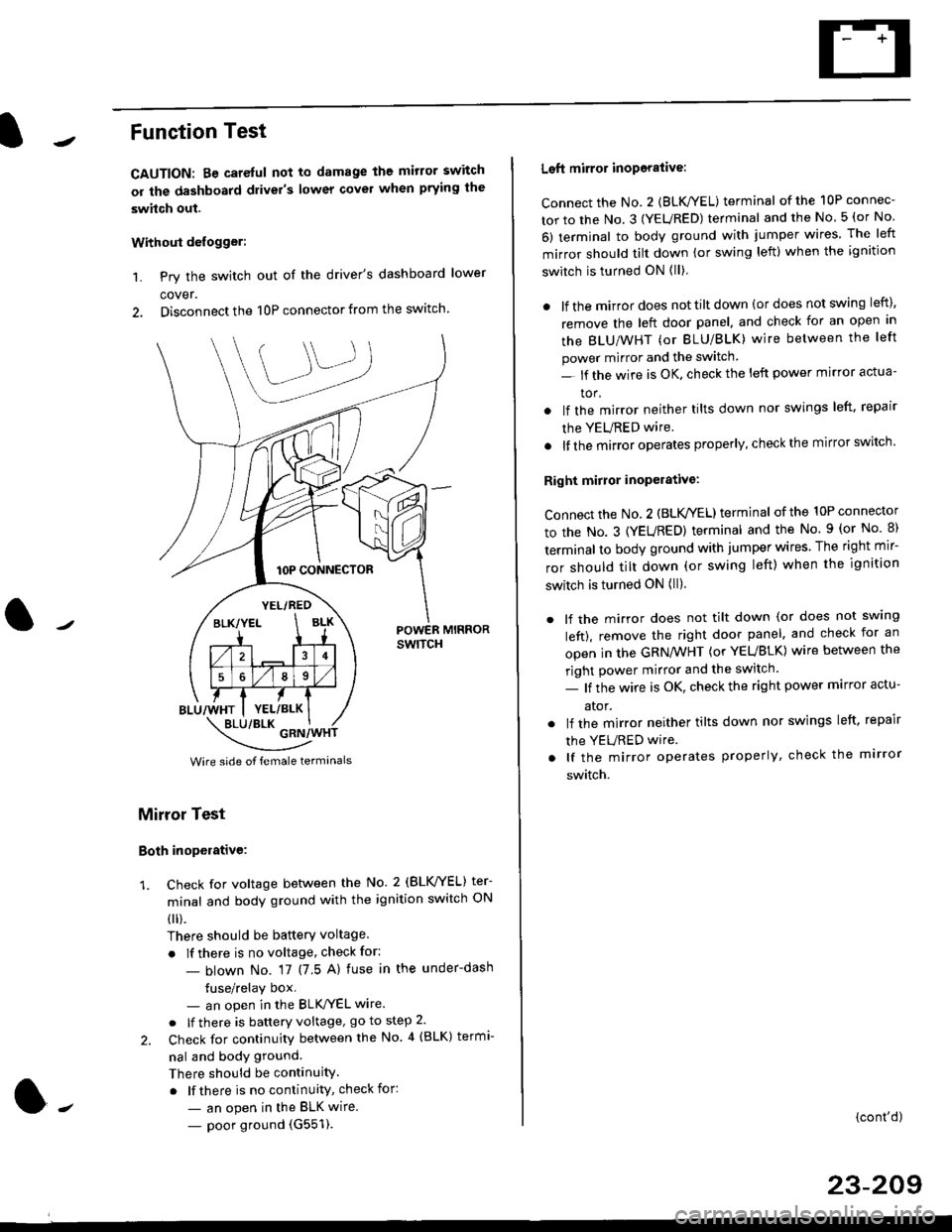
Function Test
CAUTION: Be careful not to damage the mirror switch
or the dashboard drivel's lower covel when prying the
swhch out.
Withoui defogger:
1. Pry the switch out of the driver's dashboard lower
cover.
2. Disconnect the 10P connector from the switch.
lOP CONNECTOR
BLU/WHT
YEL/RED
BLK/YELBLK
4
568
YEL/BLK
POWER MIRRORswtTcH
\:/"*jgil*-(
Wire side of female termanals
Mirror Test
Both inoperative:
1. check for voltage between the No. 2 (BLVYEL) ter
minal and body ground with the ignition switch ON
0 r).
There should be batterY voltage
. If there is no voltage, check for:
- blown No. 17 (7 5 A) fuse in the under-dash
tuse/relay box- an open in the BLK'/YEL wire.
o lf there is battery voltage, go to step 2.
2. Check for continuity between the No 4 (BLK) termi-
nal and body ground.
There should be continuity.
. lf there is no continuity, check for:
- an open in the BLK wire.
- poor ground (G551).
Left mirror inoporalive:
connect the No. 2 {BLK/YEL) terminal of the 10P connec-
tor to the No. 3 (YEURED) terminal and the No 5 (or No
6) terminal to body ground with jumper wires The left
mirror should tilt down (or swing left) when the ignition
switch is turned ON (ll)
. lf the mirror does not tilt down (or does not swing left),
remove the left door panel. and check for an open in
the BLU/WHT (or BLU/BLK) wire between the left
power mirror and the switch
- lf the wire is OK. check the left power mirror actua-
tor.
lf the mirror neither tilts down nor swings left. repair
the YEURED wire.
lf the mirror operates properly, check the mirror switch'
Right mirror inoperative:
Connect the No. 2 (BLK /EL) terminal of the 10P connector
to the No. 3 (YEURED) terminal and the No. 9 (or No 8)
terminal to body ground with jumper wires The right mir-
ror should tilt down (or swing left) when the ignition
switch is turned ON (ll).
. lf the mirror does not tilt down (or does not swlng
left), remove the right door panel. and check for an
open in the GRN/WHT (or YEUBLK) wire between the
right power mirror and the switch.
- lf the wire is OK, check the right power marror actu-
ator.
. lf the mirror neither tilts down nor swings left. repair
the YEURED wire
. lf the mirror operates properly, check the mirror
switch.
(cont'd)
23-209
Page 1680 of 2189
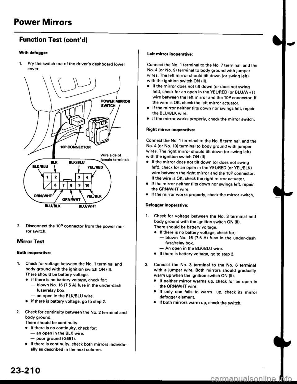
Power Mirrors
Funstion Test (cont'dl
With dcfoggcr:
1. Pry the switch out ot the driver's dashboard lowercover.
2. Disconnect the 10P coonector from the oower mir-ror switch.
Mirror Test
Bolh inoparrtiv.:
1. Check for voltage between the No. 1 terminal andbody ground with the ignition switch ON flt).There should be battery voltage.. lf there is no battery voltage, check to.:- blown No. 16 (7.5 A) fuse in the under-dash
tuse/relay box.- an open in the BLVBLU wrre.
! lf thero is banery voltage, go to step 2.
2. Check for continuity b€tween the No. 2 terminal andbody ground.
There should be continuitv.. ll there is no continuity, check tor:- an open in the BLK wire.- poor ground (G5511.
. lJthere is continuity. check both mirrors individu-ally 8s described in the next column,
23-210
Laft mirror inopcrativ!:
Connect the No. 1 terminal to the No. 7 terminal. and theNo. 4 (or Nb.9) terminalto body ground with jumper
wires. The left mirror should tilt down (or swing left)with the ignition switch ON (ll).
. lf the mirror does not tilt down (o. does not swinglett), check for an open in the YEURED (or BLUMHT)wire between the left mirror and the 10p connector. lfthe wire is OK, check the left mirror actuator.a lf the mirror neither tilts down nor swings left, repairthe BLU/BLK wire.
t lf the mirror works properly, check the mirror switch.
Right mi.ror inopcrativc:
Connect the No. 1 terminal to the No. 8 terminal, and theNo.4 (or No. 10) terminalto body ground with l'umperwi.es. The right mirror should tilt down (or swing lett)with the ignition switch ON (ll).
. lf the mirror does not tilt down {or does not swingleft), check for an open in the YEURED {or YEUBLK)
wire between the right mirror and the l0P connector.lf the wire is OK, check the right mirror actuator,. lf the mirror neither tilts down nor swings left, repairthe GRN/WHT wire.o lf the mirror works properly. check the mirro. switch,
Dafoggcr inoperEtivo:
1. Check for voltage between the No. 3 terminal andbody ground with the ignition switch ON (||).
There should be battery voltage.a lf there is no battery voltage, check for;- blown No. 16 (7.5 A) luse in the under-dash
fuse/rel8y box,- An open in the BLK,iBLU wire.. It there is battery voltage, go to step 2.
2. Connsct the No. 3 tsrminal to the No. 6 terminalwith a iumpsr wire. Both mirrors should gradually
warm up when the ignition switch ON flt).a lf neither mirror warms up, check for an open inthe ORN/WHT wire.. It only on€ lails to warm up, check its mirrordsfogger elem6nt.. lf both mirrors warm up, check ths switch.
Page 1681 of 2189
I
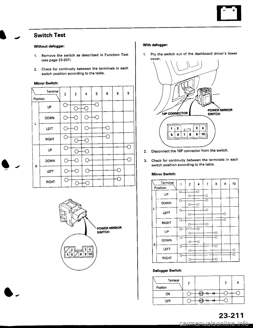
r Switch Test
Without detogg€r:
1. Remove the switch as dsscribed in Function Test
(see page 23-207).
2. Check for continuity betw€en the terminals in each
switch position according to the table.
Mirror Switch:
POWER MIRROB
swlTcH
Terminal
rL*"--_\
23456n9
L
UP-o
o-
DOWNo--oo--o
LEFTo-o--o
RIGHTo--o
o--o
UPo--o
o--o
DOWNo--oo--o
LEFIo--oo--o
RIGHT-o
o--o
l-
23-211
1. Prv the switch out of the dashboard driver's lower
With defogger:
POWER MIRRORswtTcH
Disconnect the 1OP connector from the switch'
Check for continuity between the terminals in each
switch position according to the table
Mirror Switch:
Terminal
Position \l2789't0
L
UPo-o-
-o-o
DOWNo-o--o-a
o-
o-
-o--o
RIGHTo--o
o--O
UPGo-
-o-o
DOWNo--o
G--o
LEFTo--o-oo-
RIGHT
-o
o--o
Dofogger Swhch:
Terminal
Posilion \
2
ONo-/l>\-osv
OFFo---o
Page 1682 of 2189
Power Mirrors
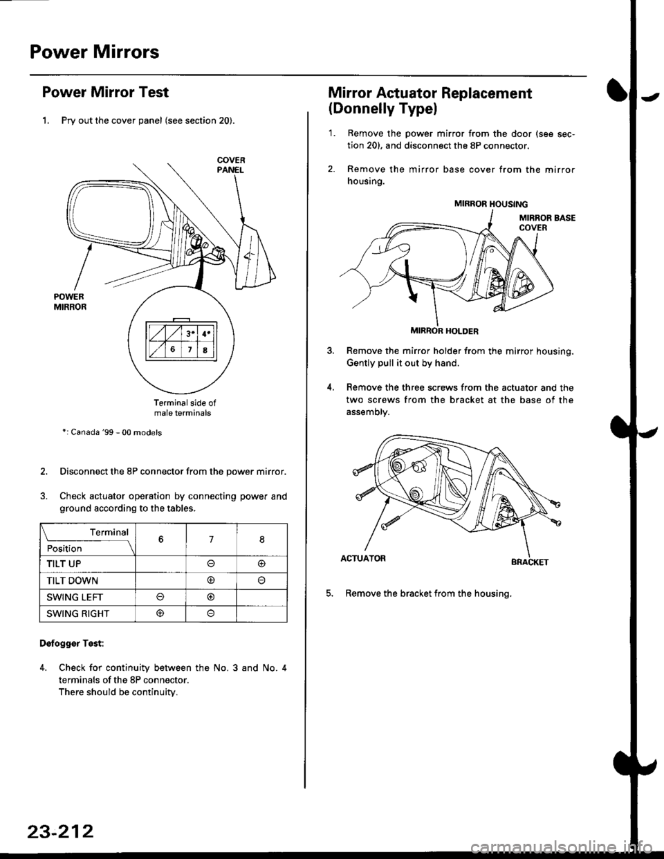
Power Mirror Test
1. Pry out the cover panel (see section 20).
Terminalside ofmale terminals
*: Canada '99 - 00 models
Disconnect the 8P connector from the power mirror.
Check actuator operation by connecting power and
ground according to the tables.
Dofogger Test:
4. Check for continuity between the No. 3 and No. 4
terminals of the 8P connector.
There should be continuity.
COVER
L___r"'ry1Position67I
TILT UPo@
TILT DOWN@
SWING LEFTo@
SWING RIGHT@
23-212
Mirror Actuator Replacement
(Donnelly Typel
'1. Remove the power mirror from the door {see sec-
tion 20). and disconnect the 8P connector.
2. Remove the mirror base cover from the mirror
housing.
MIRROR HOLDER
Remove the mirror holder from the mirror housing.
Gently pull it out by hand.
Remove the three screws from the actuator and the
two screws from the bracket at the base of the
assemory.
BRACKET
5. Remove the bracket from the housinq.
4.
MIRROR HOUSING
Page 1683 of 2189
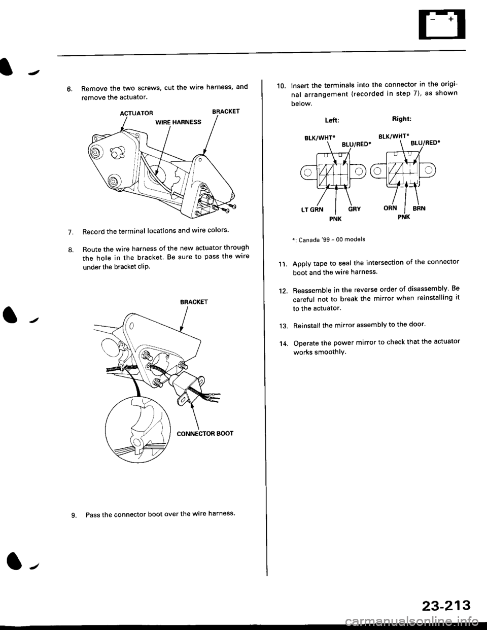
7.
8.
6. Remove the two screws, cut the wire harness, and
remove the actuator.
Record the terminal locations and wire colors'
Route the wire harness of the new actuator through
the hole in the bracket. Be sure to pass the wlre
under the bracket cliP.
BRACKET
9. Pass the connector boot over the wire harness
23-213
BLK/WHTi
,t
L,
.;{
I
oa
LT GRN I GRY
PNK
10, lnsert the terminals into the connector in the origi-
nal arrangement (recorded in step 7), as shown
Detow.
Right:
SLK/WHT*
BLU/REO'
": Canada '99 - 00 models
Apply tape to seal the intersection of the connector
boot and the wire harness.
Reassemble in the reverse order of disassembly Be
careful not to break the mirror when reinstalling it
to the actuator.
Reinstall the mirror assembly to the door.
Operate the power mirror to check that the actuator
works smoothlY.
Left:
11.
12.
13.
't 4.
PNK
Page 1687 of 2189
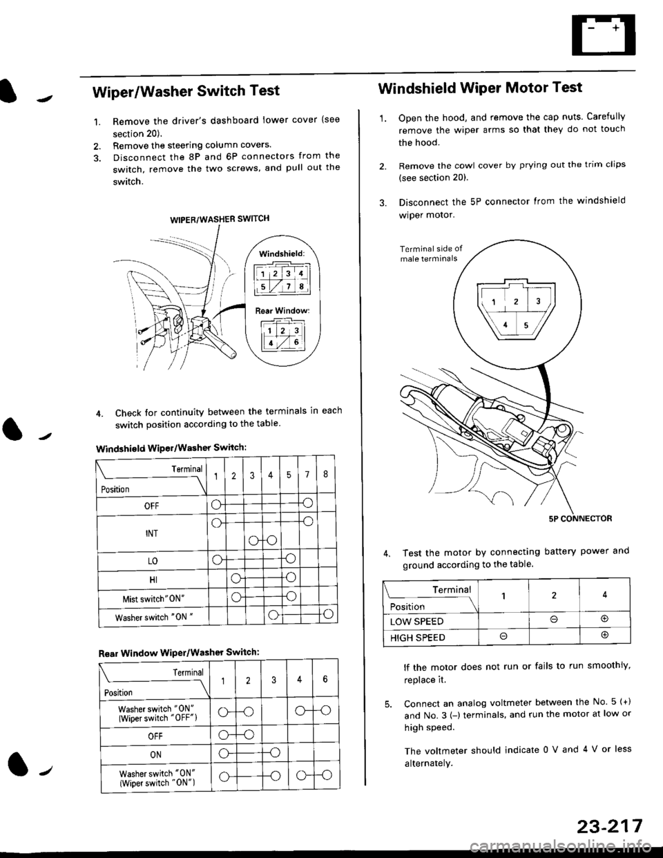
Wiper/Washer Switch Test
Remove the driver's dashboard lower cover {see
section 20).
Remove the steering column covers.
Disconnect the 8P and 6P connectors from the
switch, remove the two screws, and pull out the
switch.
4. Check tor continuity between the terminals in each
switch position according to the table
Windshield Wiper/Washer Switch:
Terminal
Position \
12357I
OFFoo
INTo-o
oo
LOoo
HIoo
l\4ist switch"0N"oo
Washer switch "0N "oo
Rear Window WiPer/Washer Switch:
I Terminal
'i"*
--J2346
Washer switch "0N"
(Wiper switch "OFF"lo--oo--o
OFFo--o
ONo--o
Washer switch "0N"
{Wiper switch "0N")o--oo--o
1.
WIPER/WASHER SWITCH
Windshield:
l1 2 314 |
li.l7a,lil
Rear Window:
11 z 3l
lT-,rtl
Windshield Wiper Motor Test
1.Open the hood, and remove the cap nuts. Carefully
remove the wiper arms so that they do not touch
the hood.
Remove the cowl cover by prying out the trim clips
(see section 20).
Disconnect the 5P connector lrom the windshield
wiper motor.
Test the motor by connecting battery power
ground according to the table.
lf the motor does not run or fails to run smoothiy,
replace it.
5. Connect an analog voltmeter between the No. 5 {+)
and No.3 {-) terminals. and run the motor at low or
high speed.
The voltmeter should indicate 0 V and 4 V or less
alternately.
Terminal
i**l*-
-_\14
LOW SPEEDo@
HIGH SPEEDo@
23-217