Power lock HONDA CIVIC 1996 6.G Repair Manual
[x] Cancel search | Manufacturer: HONDA, Model Year: 1996, Model line: CIVIC, Model: HONDA CIVIC 1996 6.GPages: 2189, PDF Size: 69.39 MB
Page 1617 of 2189
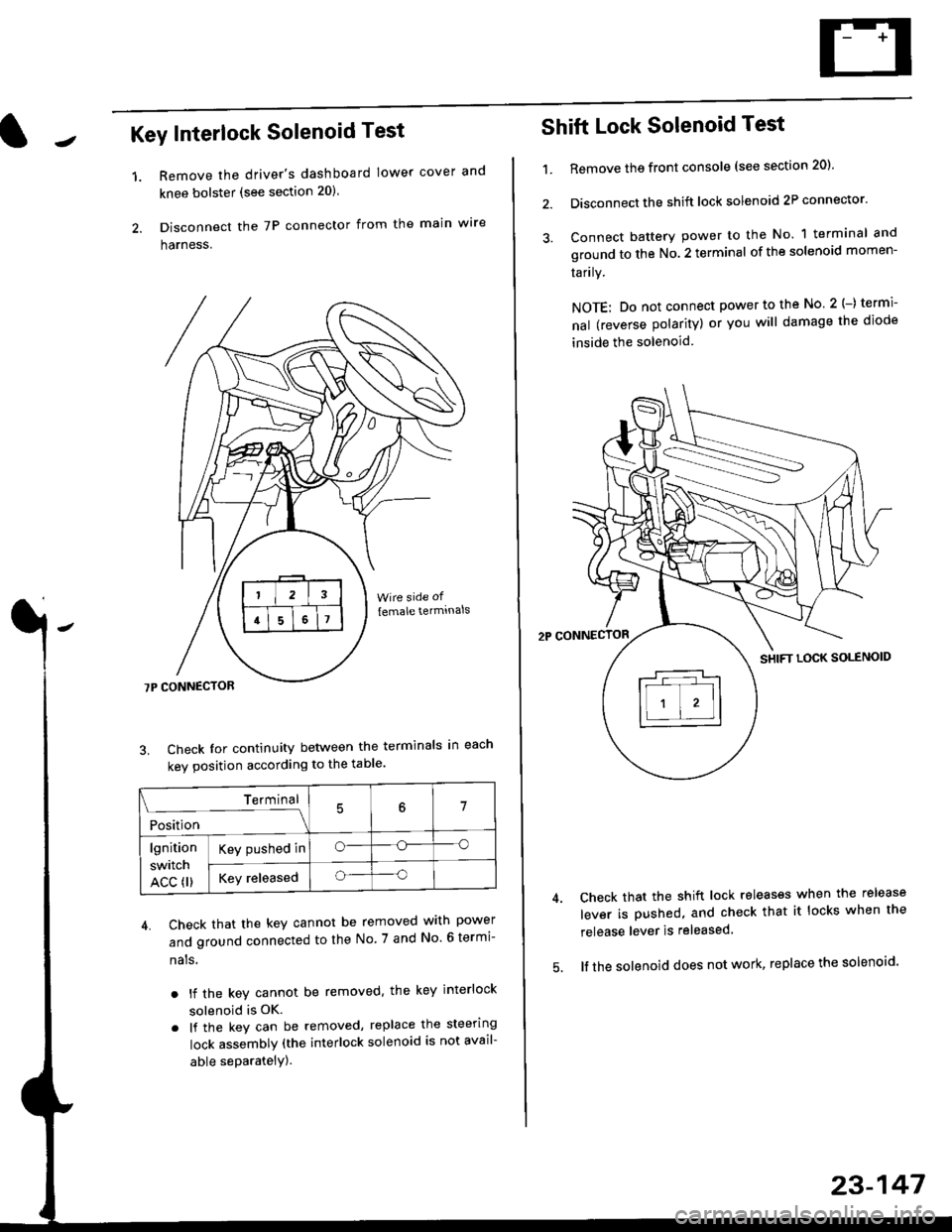
Key Interlock Solenoid Test
Remove the driver's dashboard lower cover and
knee bolster (see section 20)
Disconnect the 7P connector from the main w're
harness.
3. Check Ior continuity between the terminals in each
kev oosition according to the table'
4. Check that the key cannot be removed with power
and ground connected to the No. 7 and No 6 termi-
nals
. lf the key cannot be removed. the key interlock
solenoid is OK.
. lf the key can be removed, replace the steering
lock assembly (the interlock solenoid is not avail-
able seParatelY).
1.
Terminal
i*i,r"
- - --\7
lgnition
switch
ACC fl)
Key pushed ino--o
Key releasedo--o
Shift Lock Solenoid Test
't.Remove ths front console (see section 20)'
Disconnect the shift lock solenoid 2P connector'
Connect battery power to the No. 1 terminal and
ground to the No. 2 terminal of the solenoid momen-
Iarrry.
NOTE: Do not connect power to the No 2(-) termi-
nal (reverse polarity) or you will damage the diode
inside the solenoid
Check that the shift lock releases when the release
lever is pushed, and check that it locks when the
release lever is released
lf the solenoid does not work, replace the solenoid'
23-147
Page 1688 of 2189
Wipers/Washers
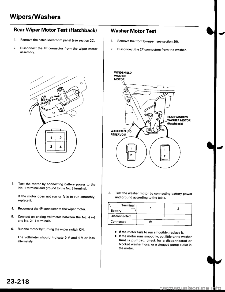
Rear Wiper Motor Test (Hatchback)
1.Remove the hatch lower trim panel (see section 20).
Disconnect the 4P connector from the wiper motorassemDry,
Test the motor by connecting battery power to theNo. 1 terminal and ground to the No. 3 terminal.
lf the motor does not run or fails to run smoothly,reptace rI.
Reconnect the 4P connector to the wiper motor.
Connect an analog voltmeter between the No. 4 (+)
and No.2 (-)terminals,
Run the motor by turning the wiper switch ON.
The voltmeter should indicate 0 V and 4 V or lessalternately.
23-218
1.
Washer Motor Test
Remove the front bumper (see section 20).
Disconnect the 2P connectors from the washer,
a
a
lf the motor fails to run smoothly, replace it.lf the motor runs smoothly. but little or no wasnerfluid is pumped. check for a disconnecr€o orblocked washer hose, or a clogged pump outlet inthe motor.
REAR WINDOWWASHER MOTOR(Hatchbackl
WASHER FLUIORESERVOIR
3. Test the washer motor by connecting battery power
and ground according to the table.
L f:,ry1Battery1
Disconnected
Connected@
Page 1721 of 2189
Power Door Locks
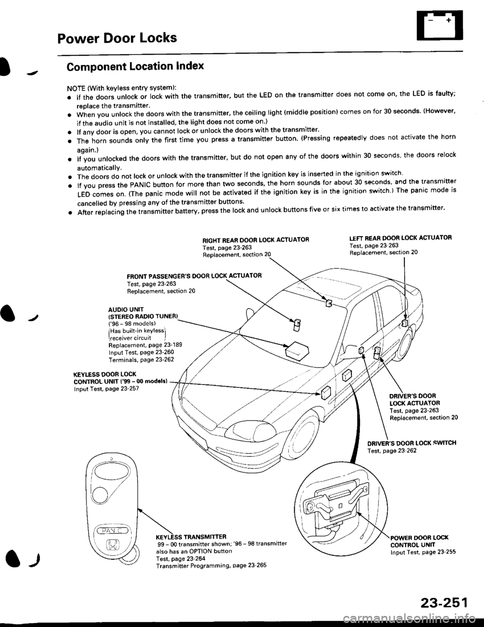
Component Location Index
NOTE (With keyless entry systeml:
. It the doors unlock or lock with the transmitter, but the LED on the transmitter does not come on, the LED is faulty;
replace the transmitter'
. when vou unlock the doors with the transmitter, the ceiling light (middle position) comes on for 30 seconds. (However,
if the audio unit is not installed, the light does not come on )
. lf any door is open, you cannot lock or unlockthe doors with the transmitter'
. The horn sounds only the first time you press a transmitter button. (Pressing repeatedly does not activate the horn
again.)
o lf vou unlocked the doors with the transmitter, but do not open any of the doors within 30 seconds, the doors relock
automatically.
. The doors do not lock or unlock with the transmitter if the ignition key is inserted in the ignition switch
. lf you press the PANIC button for more than two seconds, the horn sounds for about 30 seconds, and the transm'fer
LED comes on. (The panic mode will not be activated iJ the ignition key is in the ignition switch ) The panic mode is
cancelled by pressing any of the transmitter buttons'
o After replacing the transmitter battery, press the lock and unlock buttons five or six times to activate the transmitter'
Replacement, section 20
FRONT PASSENGER'S DOOR LOCK ACTUATOR
RIGHT REAR DOOR LOCK ACTUATOR
Test, page 23-263
I.IFT REAR DOOR LOCK ACTUATOR
Test, page 23 263Replacement, section 20
LOCK ACTUATORTest, page 23-263Replacement, section 20
ORIVER'S DOOR LOCK SWITCH
Test, page 23'262
DOOR L@XCONTROL UN]TInput Test, page 23 255
23-251
Test, page 23-263Replacement, section 20
AUDIO UNIT(STER€O RADIO TUNER)
{'96 - 98 models)
lHas built-in keylessl
eceiver circuit IReplacement, page 23-189
Input Test, page 23-260
Terminals, page 23-262
KEYLESS DOOR LOCKCONTROL UNIT l'99 - 00 modelsl
Input Test, Page 23-257
l-l
TRANSMITTER99 - 0O transmitter shown;'96 -98 transmifter
also has an OPTION buttonTest, page 23-264Transmitter Programming, page 23_265
Qi,,a/
/----
L(ru
i'.-8,-'l
/'-'6
Page 1722 of 2189
Power Door Locks
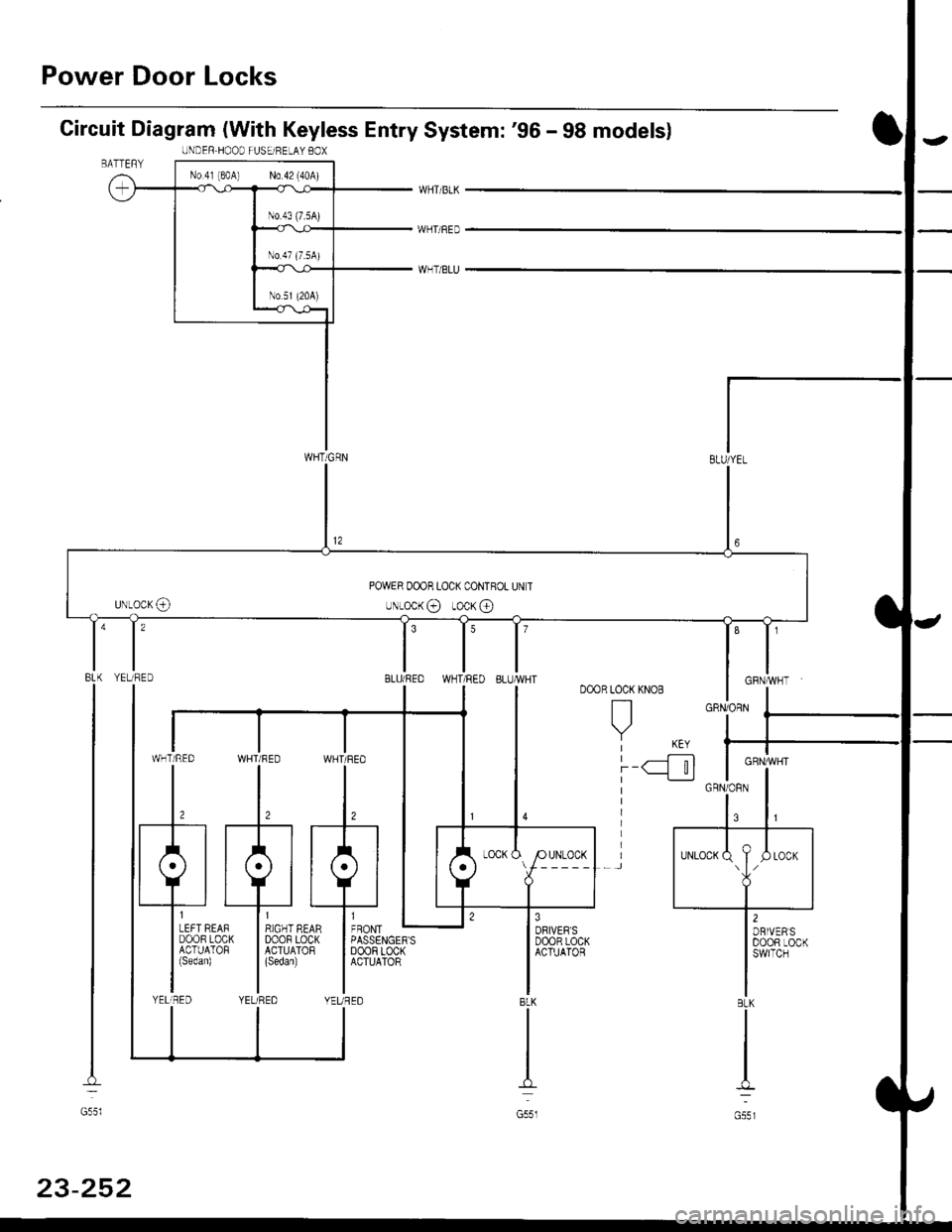
Circuit Diagram (With Keyless Entry System: '96 - 98 modelsl
WHTi BLK
WHT/BED
WHT/BLU
LOCK KNOB
n
Y KEY| -----.f--;-)
i-q__!J
8LK
G551
ll,o"., L
I PASSENGER'SI DoOF LOCKI ACTUATOR
IIYEUREO
WHT/RED WHT/FED
l,l,
tA-r rA] r.
qJ_*:[:,,,:
liqi*"""r llqi*'€trYELIRED YELi REDBLK
I
No.4l 180A) N0.42 (40A)
WHT/GRN
UNDER.HOOD FUSEi RELAY BOX
POWER OOOR LOCK CONTROL UN T
uNLocK@ rocK @
t'8LU/REDI'YELTRED
GRNiORN
GRN/]/VHT
BLK
G55l
23-252
Page 1724 of 2189
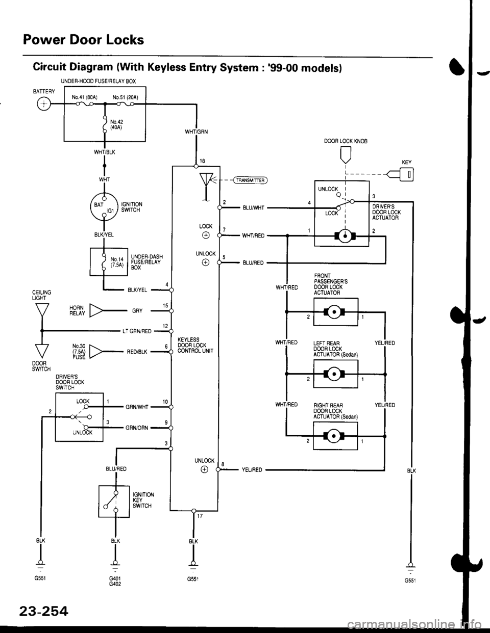
Power Door Locks
Circuit Diagram (With Keyless Entry System : '99-00 models)
BL(
I
G551
UNDEF.HOOO FUSE/RELAY BOX
N0.41 1804) N0.51 (20 )
KEYLESSDOOF LOCKCOIJTROL UNIT
DRIVEF'SDOOF LOCKSWITCH
23-254
Page 1725 of 2189
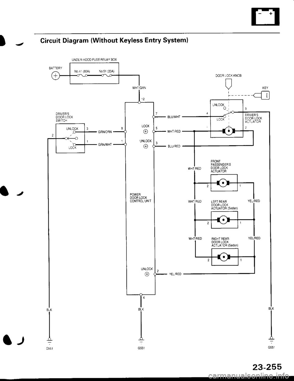
UNDER HOOD FUSE/RELAY BOX
)1Circuit Diagram (Without Keyless Entry System)
Ir
l -,t
l'8LK
G551
23-255
ORIVER'SDOOR LOCKSW TCH
BLK
G55l
POWERDOOR LOCKCONTROT UN T
Page 1726 of 2189
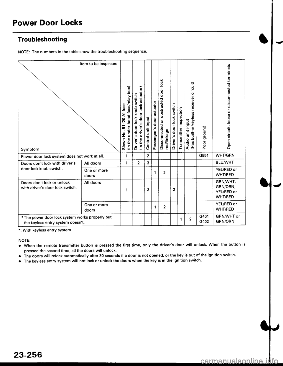
Power Door Locks
Troubleshooting
NOTE: The numbers in the table show the troubleshooting sequence.
*: With keyless entry system
NOTE:
. When the remote transmitter button is pressed the first time, only the driver's door will unlock. When the button is
pressed the second time, all the doors will unlock.
. Thedoorswill relock a utomatica lly after 30 seconds if a door is not opened, or the key is out ot the ign ition switch.
. The keyless entry system will not lock or unlock the doors when the key is in the ignition switch.
Item to be inspected
Symptom
s
{o
x6
tn6
l5
€5
5O
o:E,
ooo>
o
;
o
>t
6<
o:
3
:o
o
.9
':
E
F
q)
<5
I
E
c
Power door lock svstem does not work at all.1ucc IWHT/GRN
Doors don't lock with driver's
door lock knob switch.
All doorsI2BLU,ryVHT
One or more
doors
YEURED or
WHT/RED
Doors don't lock or unlock
with driver's door lock switch.
All doors
1
GRN/WHT,
GRN/ORN,
YEURED or
WHT/RED
One or more
ooors
YEURED or
WHT/RED
*The power door lock system works properly but
the keyless entry system doesn't.1G401
G402
GRNAVHT or
GRNiORN
23-256
Page 1728 of 2189
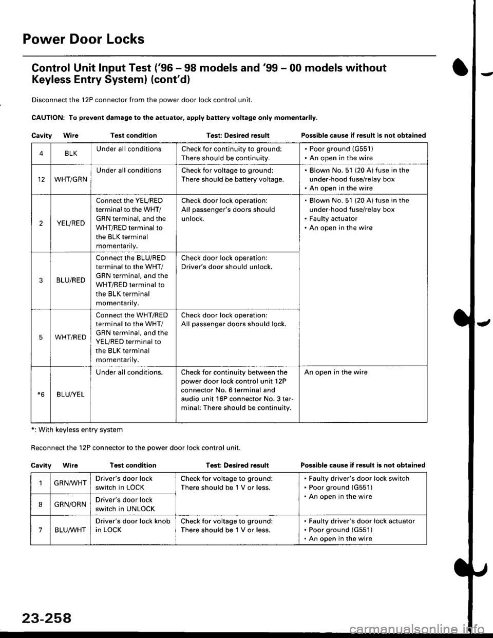
Power Door Locks
Control Unit lnput Test ('96 - 98 models and'99 - 00 models without
Keyless Entry Systeml (cont'dl
Disconnect the 12P connector from the power door lock control unit.
CAUTION: To prevsnt damage to the actuator, apply battery voltage only momentarily.
Cavity WireTest conditionTest: Desired resultPossible cause if result is nol obtained
*: With keyless entry system
Reconnect the 12P connector to the power door lock control unit.
Cavity WireTest conditionTssl: Desirsd losullPossible cause it resull b not obtained
4BLKUnder all conditionsCheck for continuity to ground:
There should be continuity.
. Poor ground (G55'l ). An open in the wire
WHT/GRN
Under all conditionsCheck for voltage to ground:
There should be battery voltage.
. Blown No. 51 (20 A)fuse in the
under-hood fuse/relay box. An open in the wire
2YEURED
Connect the YEURED
terminal to the WHT/
GRN terminal, and the
WHT/RED terminal to
the BLK terminal
momenraflty.
Check door lock operation:
All passenger's doors should
untocK.
Blown No. 51 {20 A) fuse in the
under-hood fuse/relay box
Faulty actuator
An open in the wire
3BLU/RED
Connect the BLU/RED
terminal to the WHT/
GRN terminal. and the
WHT/RED terminal to
the BLK terminal
momenraflry.
Check door lock operation:
Driver's door should unlock.
5WHT/RED
connect the WHT/RED
terminal to the WHT/
GRN terminal, and the
YEL/RED terminal to
the BLK terminal
momenrafl ty.
Check door lock operation:
All passenger doors should lock.
BLU/YEL
Under all conditions.Check for continuity between the
power door lock control unit l2P
connector No. 6 terminal and
audio unit 16P connector No. 3 ter-
minal: The.e should be continuity.
An open in the wire
GRN,ryVHTDriver's door lock
switch in LOCK
Check for voltage to ground:
There should be 1 V or less.
Faulty driver's door lock switch
Poor ground {G551)
An open in the wire
8GRN/ORNDriver's door lock
switch in UNLOCK
7BLUA/VHT
Driver's door lock knob
in LOCK
Check for voltage to ground:
There should be 1 V or less.
Faulty driver's door lock actuator
Poor ground {G551)
An open in the wire
Page 1729 of 2189
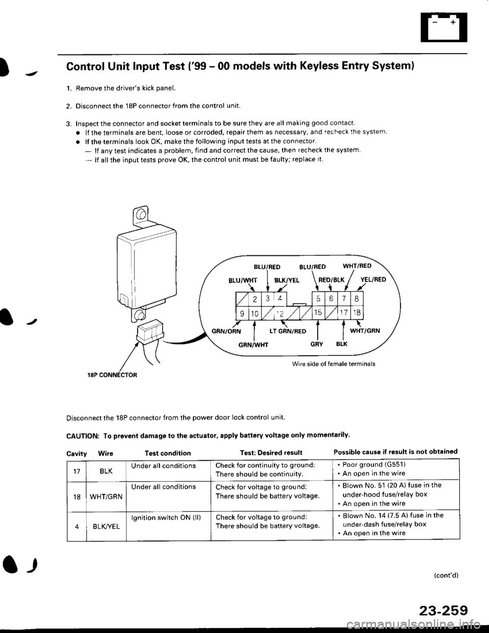
)Control Unit Input Test ('99 - 00 models with Keyless Entry System)
1.Remove the driver's kick panel.
Disconnect the 18P connector from the control unit.
Inspect the connector and socket terminals to be sure they are all making good contacl.
. lf the terminals are bent, loose or corroded, repair them as necessary, and recheck the system
. lf the terminals look OK, make rhe following input tests at the connector.
- lf anv test indicates a problem, find and correct the cause, then recheck ihe system
- lf all the input tests prove OK, the control unit must be faulty; replace it
Wire side oI female terminals
Disconnect the 18P connector from the power door lock control unit.
CAUTION: To provent damage to the actuator, apply battery Yoltage only momentarily.
Cavity Wir€ Test conditionTest: Desired resultPossible cause if result is not obtained
BLK/YELRED/SLK
25618
910/,'2 ,/
'151718
LTWHT
17BLKUnder all conditionsCheck for contlnuity to ground:
There should be continuity.
. Poor ground (G551)
. An open in the wire
t8WHT/GRN
Under all conditionsCheck tor voltage to ground:
There should be battery voltage.
. Blown No. 5'1 (20 A) luse in the
under-hood tuse/relay box
. An open in the wire
4B LK/YEL
lgnition switch ON (ll)check for voltage to ground:
There should be battery voltage.
Blown No. l4 (7.5 A) fuse in the
under-dash fuse/relay box
An open in the wire
(cont'd)
23-259
l-r
Page 1730 of 2189
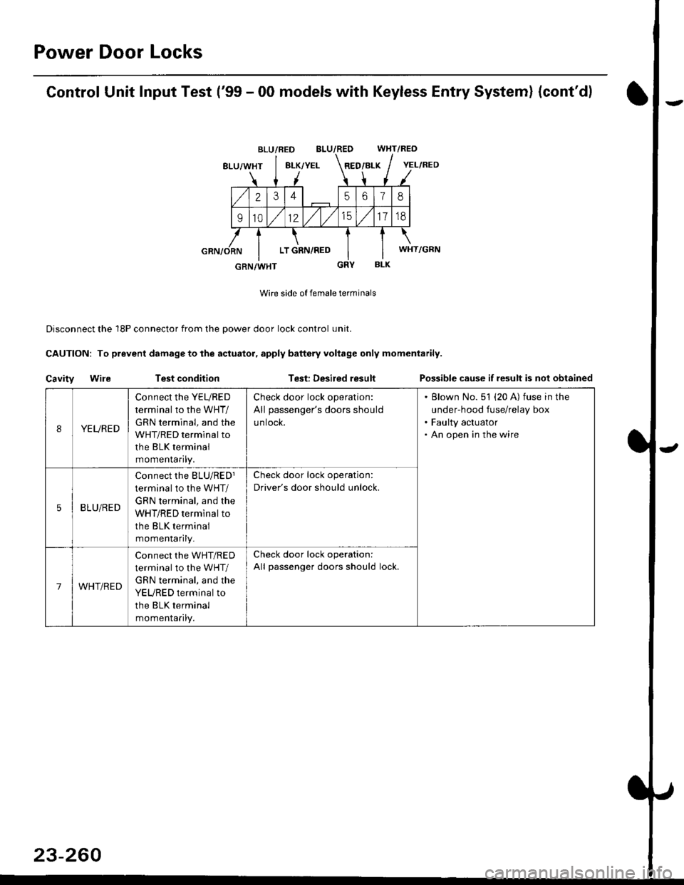
Power Door Locks
Control Unit Input Test ('99 - 00 models with Keyless Entry System) (cont'd)
BLU/RED WHT/RED
8LU/WHT8LK/YELRED/BLK
2345618
91012/t/t517td
LT GRN,/RED
BLK
Wire side of female terminals
Disconnect the 18P connector from the oower door lock control unit.
CAUTION: To prevent damage to the actuator, apply baftery voltage only momentarily.
Cavity WileTest conditionTest: Desired resultPossible cause if result is not obtained
BLU/RED
YEL/RED
WHT/GRN
GRN/WHT
IYEURED
Connect the YEURED
terminal to the WHT/
GRN terminal, and the
WHT/RED terminal to
the BLK terminal
momenraflty,
Check door lock operation:
All passenger's doors should
untocK.
Blown No. 51 (20 A) fuse in the
under-hood fuse/relay box
Faulty actuator
An open in the wire
5BLU/RED
Connect rhe BLU/RED1
terminal to the WHT/
GRN terminal, and the
WHT/RED terminal to
the BLK terminal
momenlaflry_
Check door lock operation:
Driver's door should unlock.
7WHT/RED
Connect the WHT/RED
terminal to the WHT/
GRN terminal, and the
YEURED terminal to
the BLK terminal
momenlaflry.
Check door lock operation:
All passenger doors should lock.
23-260