under dash fuse box HONDA CIVIC 1996 6.G Repair Manual
[x] Cancel search | Manufacturer: HONDA, Model Year: 1996, Model line: CIVIC, Model: HONDA CIVIC 1996 6.GPages: 2189, PDF Size: 69.39 MB
Page 1574 of 2189
![HONDA CIVIC 1996 6.G Repair Manual lgnition System
Circuit Diagram :98-00 models
UNDER HOOD FUSUFELAY BOXxE;;;;-;;;;l /; l-*;- Ecw.cM
ffiwFnBLK<-wHr\9-
Y
tlBTKTYEL YEUGRN
IGN]TIONswtTcHUNDER,DASHFUSE/BELAY BOX
YEt
J
BLK
J
FED
+
*1 HONDA CIVIC 1996 6.G Repair Manual lgnition System
Circuit Diagram :98-00 models
UNDER HOOD FUSUFELAY BOXxE;;;;-;;;;l /; l-*;- Ecw.cM
ffiwFnBLK<-wHr\9-
Y
tlBTKTYEL YEUGRN
IGN]TIONswtTcHUNDER,DASHFUSE/BELAY BOX
YEt
J
BLK
J
FED
+
*1](/img/13/6068/w960_6068-1573.png)
lgnition System
Circuit Diagram :'98-00 models
UNDER HOOD FUSUFELAY BOX'x'E;;;;-;;;;l /; l-*;- Ecw.cM
ffiwFnBLK<-wHr\9-
Y
tlBTKTYEL YEUGRN
IGN]TIONswtTcHUNDER,DASHFUSE/BELAY BOX
YEt
J
BLK
J
FED
+
*1 :H TACHI*2 :TEC
9 *IBLU'
23-104
Page 1579 of 2189
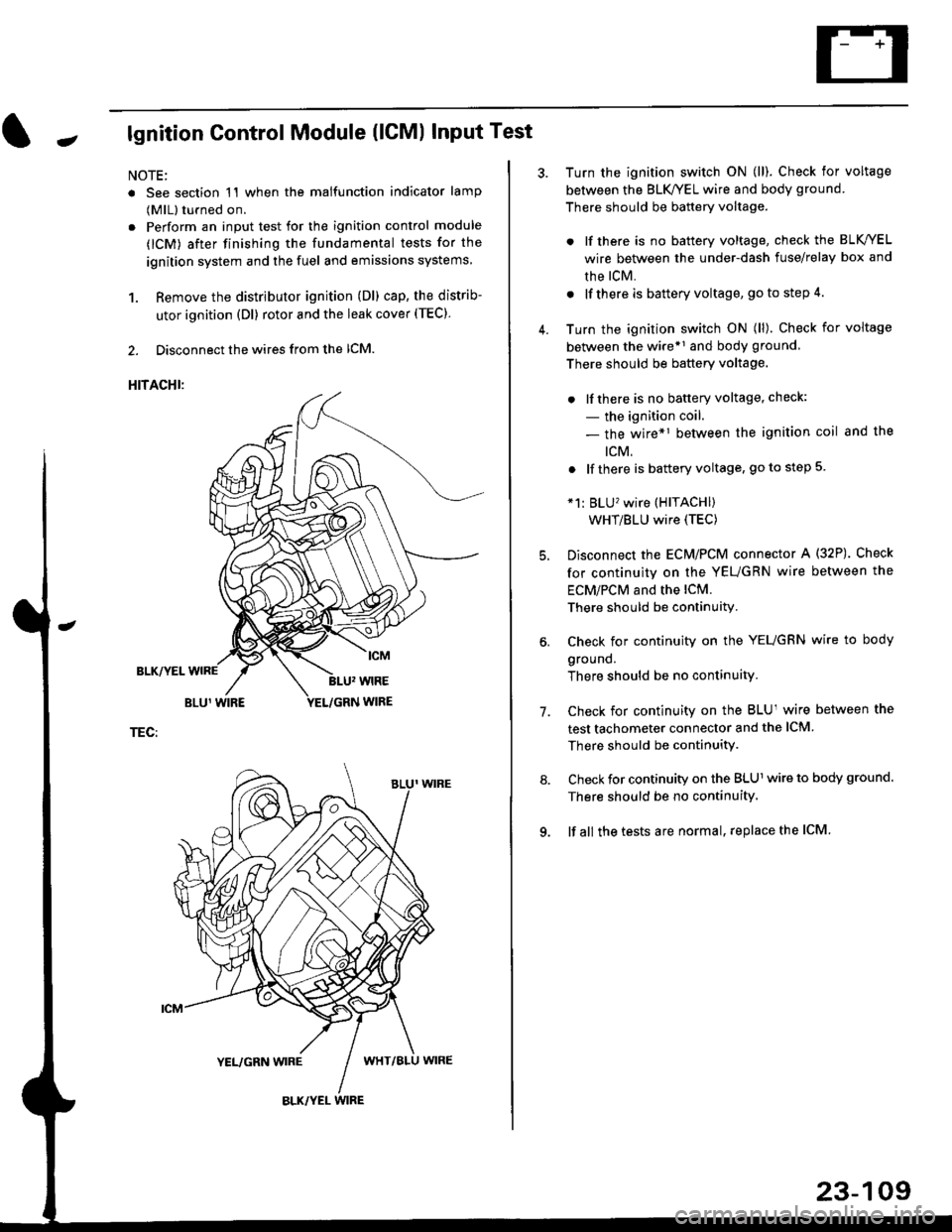
Jlgnition Control Module (lCMl Input Test
NOTE:
. See section 1'l when the malfunction indicator lamp
(MlL) turned on.
. Perform an input test for the ignition control module
(lCM) after finishing the fundamental tests for the
ignition system and the fuel and emissions systems
1. Remove the distributor ignition (Dl) cap, the distrib-
utor ignition (Dl) rotor and the leak cover (TEC).
2. Disconnect the wires from the lCM.
HITACHI:
BLK/YEL
TEC:
Turn the ignition switch ON (ll). Check for voltage
between the BLK/YEL wire and body ground.
There should be battery voltage.
. lf there is no battery voltage, check the BLK/YEL
wire between the under-dash fuse/relay box and
rhe lcM.
. lf there is battery voltage, go to step 4.
Turn the ignition switch ON (ll). Check for voltage
between the wire*r and body ground
There should be battery voltage.
. lfthere is no battery voltage, check:
- the ignition coil.
- the wire*1 between the ignition coil and the
tcM.
. lf there is battery voltage, go to step 5
*1: BLU'�wire (HITACHI)
WHT/BLU wire (TEC)
Disconnect the EcM/PCM connector A (32P). Check
for continuity on the YEUGRN wire between the
ECM/PCM and the lCM.
There should be continuity.
Check for continuity on the YEUGRN wire to body
ground.
There should be no continuity.
Check for continuity on the BLUl wire between the
test tachometer connector and the ICM
There should be continuitY.
Check for continuity on the BLUl wire to body ground.
There should be no continuity.
lf all the tests are normal, replace the ICM
7.
23-109
Page 1597 of 2189
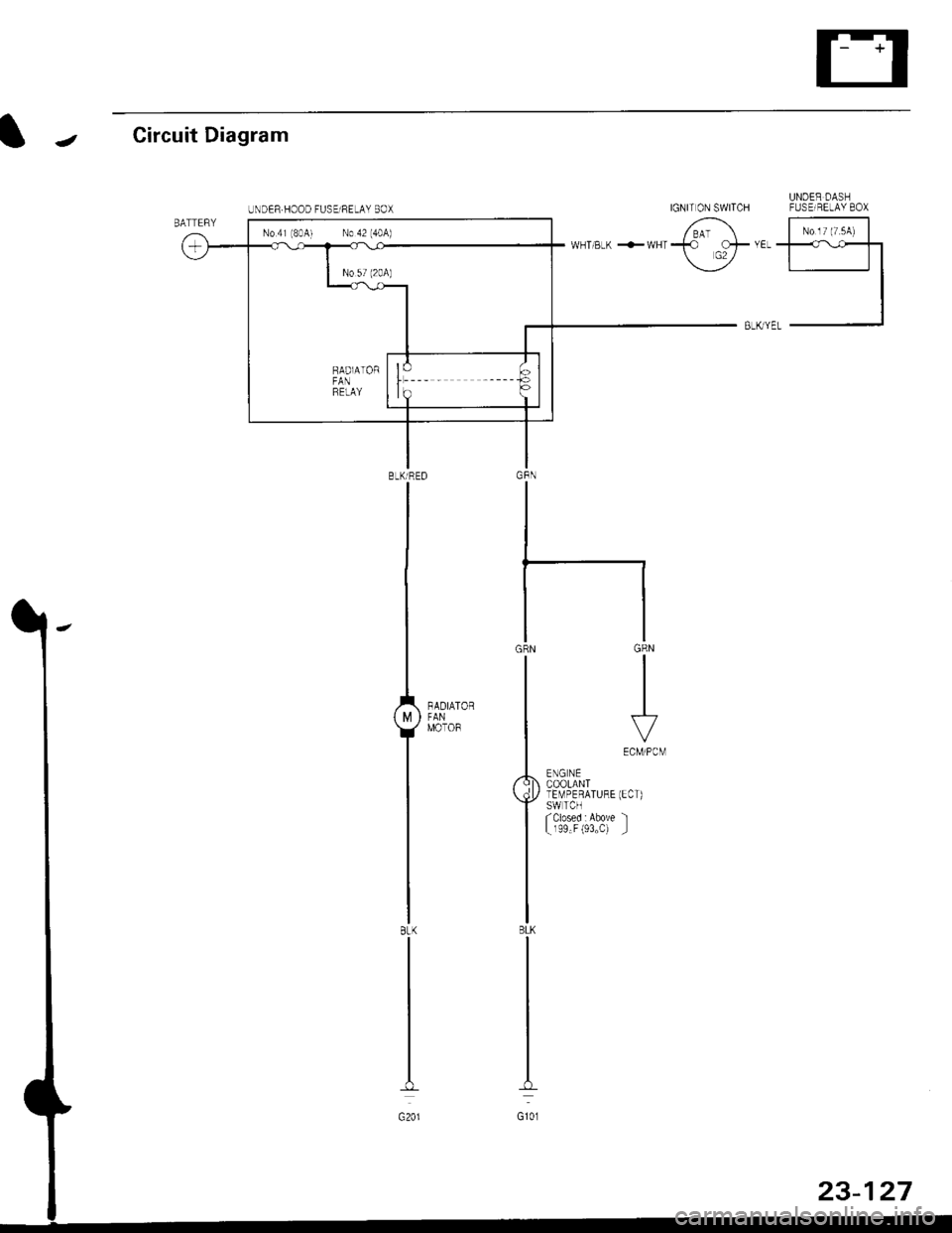
IJCircuit Diagram
UNDER DASHIGNIT ON SWITCH FUSEIRELAY 8OX
6 |-;;;;lii "ir"'t*Tl-l
BLK yEL -J
GRN
III
I
\.7VECM/PCM
ENG NECOOLANTlEMPERATURE (ECT)SWTCHfclosed : Above 'l
L r99"F (93"C) _l
BLKTRED
I
I
1,,*"_
T-'
IBtK
I
I
G201
UNDER.HOOD FUSElRELAY BOX
No 41 (8041 No 42 (40A)
Page 1610 of 2189
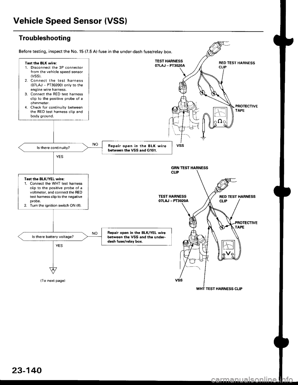
Vehicle Speed Sensor (VSSI
Troubleshooting
Before testing, inspect the No. 15 (7.5 A) fuse in the under-dash fuse/relay box.
TEST HARNESSOTLAJ _ PT3O2OAREO TEST HARNESSCLIP
PROTECTIVETAPE
TEST HARNESSOTLA' . PT3O2OA
(To next page)
Test the BLK wire:1. Disconnect the 3P connectorfrom the vehicle speed sensor(vss).
2. Connect the test harness(07LAJ PT30200) only to theengine wire harness,3. Connect the RED test harnessclip to the positive probe of a
4. Check for continuity betweenthe RED test harness clip andbody ground.
Repair opon in the BLK wireb€twe€n the VSS and G101.ls there continuity?
Te3t the BLK/YEL wire:1. Connect the WHT test harnessclip to the positive probe of avoltmeter, and connectthe REDtest harness clip to the negativeprobe.2. Turn the ignition switch ON {ll).
Repair open in iho BLK/YEL wirebetween the VSS and the under-d6sh tuse/relav box.
vss
GRN TEST HARNESS
RED TEST HARNESS
WHT TEST HARNESS CLIP
23-140
Page 1612 of 2189
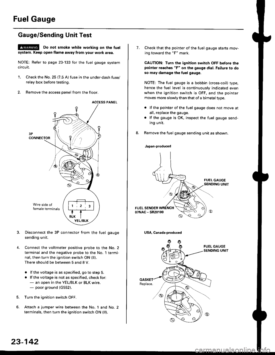
Fuel Gauge
Gauge/Sending Unit Test
!@ Do not smoke while working on tho fuel
system. Keep open tlame away trom your wotk atea.
NOTE: Refer to page 23-133 for the fuel gauge system
circuit.
'1. Check the No. 25 (7.5 A) fuse in the under-dash fuse/
relay box before testing.
2. Remove the access panel from the floor.
ACCESS PANEL
Disconnect the 3P connector from the fuel gauge
sending unit.
Connect the voltmeter positive probe to the No. 2
terminal and the negative probe to the No. I termi-
nal, then turn the ignition switch ON (ll).
There should be between 5 and 8 V.
. lf the voltage is as specified, go to step 5.
. lf the voltage is not as specified. check for:- an open in the YEUBLK or BLK wire.- poor ground (G552).
Turn the ignition switch OFF.
Attach a jumper wire between the No. 1 and No. 2
terminals, then turn the ignition switch ON (ll).
)\
23-142
1.Check that the pointer of the fuel gauge starts mov-
ing toward the "F" mark.
CAUTION: Turn the ignition switch OFF before thepoinier reaches "F" on ihe gauge dial. Failure to do
so may damage the fuel gauge.
NOTE: The fuel gauge is a bobbin (cross-coil) type,
hence the fuel level is continuously indicated even
when the ignition switch is OFF, and the pointer
moves more slowly than that of a bimetaltype.
. lf the pointer of the fuel gauge does not move at
all, replace the gauge.
. lf the gauge is OK. inspect the fuel gauge send-
ing unit.
Remove the fuel gauge sending unit as shown.
Japan-produced
USA, Canada-produced
Page 1613 of 2189
J
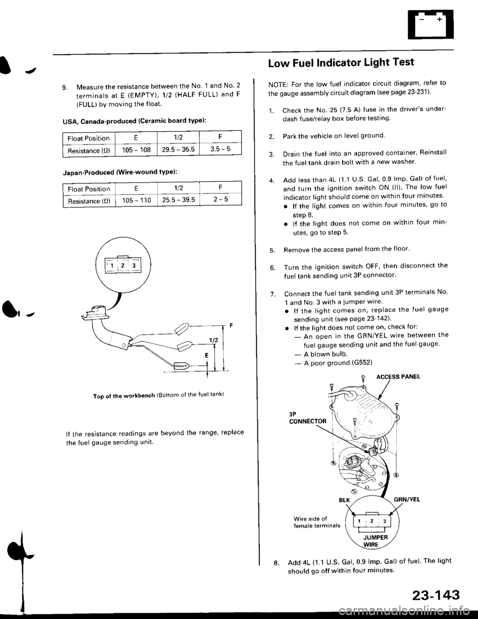
9. lMeasure the resistance between the No 1 and No. 2
terminals at E {EMPTY), 112 \HALF FULL) and F
(FULL) by moving the lloat.
USA, Canada-produced {Ceramic board type):
Too ot lhe workbench (Bottom of the fuel tank)
ll the resistance readings are beyond the range. replace
the fuel gauge sending unit
Float PositionE1t2F
Resistance (0)105 - 10829.5 - 35.53.5-5
Jaoan-Ploduced (Wire-wound typel:
Float PositionE1/2F
Resistance (O)105 - 11025.5 - 39.5
Low Fuel Indicator Light Test
NOTE: For the low fuel indicator circuit diagram, refer to
the gauge assembly circuit diagram (see page 23'2311.
1. Check the No. 25 (7 5 A) luse in the driver's under
dash fuse/relay box before testing
2. Park the vehicle on level ground.
3.
4.
Drain the luel into an approved container. Reinstall
the fueltank drain bolt with a new washer.
Add less than 4L (1 1 U.S Gal, 0.9 lmp Gal) of fuel,
and turn the ignition switch ON (ll). The low fuel
indicator light should come on within four minutes'
. lf the light comes on within four minutes, go to
step 8.
. lf the light does not come on within four min-
utes, go to step 5.
Remove the access panel lrom the Iloor'
Turn the ignition switch OFF, then disconnect the
fuel tank sending unit 3P connector.
Connect the fuel tank sending unit 3P terminals No'
1 and No. 3 with a jumPer wire
. lf the light comes on, replace the fuel gauge
sending unit (see Page 23 1421
. lf the light does not come on, check for:
- An open in the GRN/YEL wire between the
fuel gauge sending unit and the fuel gauge
- A blown bulb.- A poor ground (G552)
6.
1.
female terminals
8. Add 4L {1.1 U.S. Gal, 0 9 lmp Gal) of fuel The light
should go off within four minutes.
23-143
Page 1615 of 2189
J
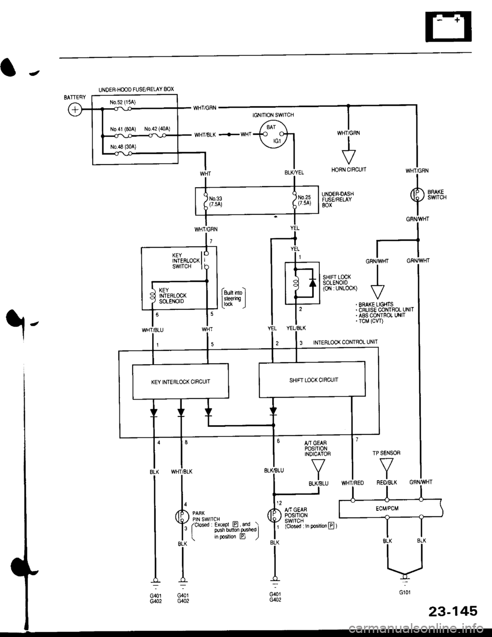
UNDER HOOD FUSARELAY BOX
No 41 (80A) N0.42 (404)
GFNWHT
WHT/GFN
UNOEF,DASHFUSE/RELAY80x
SHIFT LOCKsoLENO|0(O,l : UNLoCK)
I
5
53 INTERLOCK CONTFOL IJNIT
BLK
I
G401G402
GRNAVI{I GR}.//WHT
rl
JI
VIBRAI(E LIGHIS IcRUrsE coNTROL UNIT IABS CONTROT, UNIT IrcM (cw) I
YEL
lr
rEt
till
l'YEUBLK
M GEARPOStT|ONINDICATOF
f7
I
] SENSOR
f7
IRED/BLK
WHT/BLK
II
t,/P1 ennr
Vl$"ilT?l*r e,."o rlr I PUsh bdon frsn€o I| Inpos on B )BLK
II
I:
G401G402
KEY llTNTEnLOCK | |swrTcH I I
KEY INTERLOCK CIRCUIT
GFNWHT
POSTTTONswlTcH(Clos€d : In posilioa lll )
23-145
Page 1616 of 2189
Interlock System
Control Unit Input Test
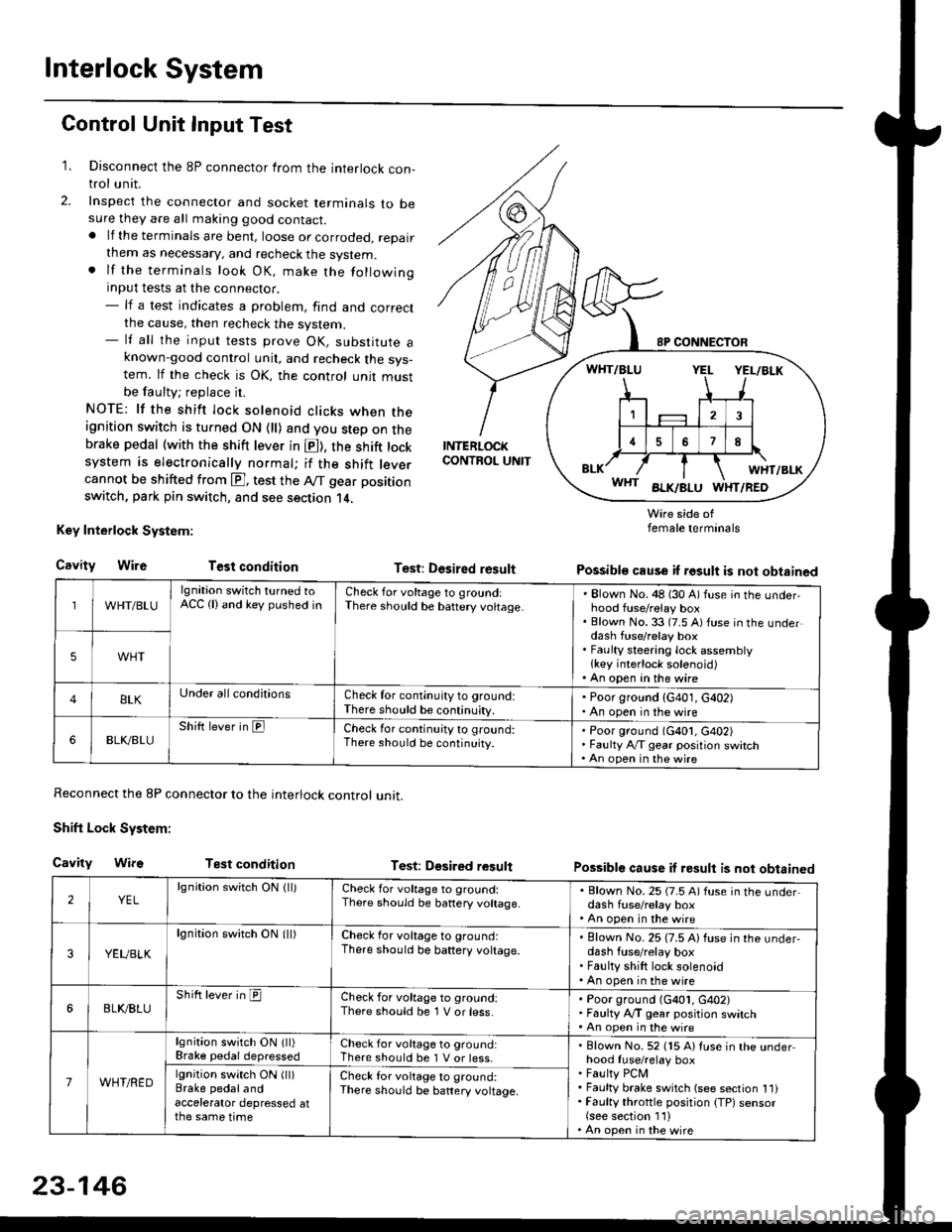
1. Disconnect the 8P connector from the interlock con-trol unit.
2. Inspect the connector and socket terminals to besure they are all making good contact.. lf the terminals are bent, loose or corroded, repairthem as necessary, and recheck the system.. lf the terminals look OK, make the followinginput tests at the connector.- lf a test indicates a problem, find and correctthe cause, then recheck the system.- lf all the input tests prove OK, substitute aknown-good control unit, and recheck the sys-tem. lf the check is OK, the control unit mustbe faulty; replace it.
NOTE: lf the shift lock solenoid clicks when theignition switch is turned ON {ll) and you step on thebrake pedal (with the shift lever in E), the shift locksystem is electronically normal; if the shift leve.cannot be shifted from E], test the Aff gear position
switch, park pin switch, and see section 14.
Key Interlock System:
CavityWireTest condition
Reconnect the 8P connector to the interlock control unit.
Shift Lock System:
Cavity WifsTest condition
INTERLOCKCONTROL UNIT
Test: Desired result
Test: Dgsired result
Wire side offemale terminals
Possible cause if result is not obtained
Possible cause if result is not obtained
WHT/BLU
lgnition switch turned toACC (lland key pushed inCheck for voltage to groundiThere should be baftery voltage.Blown No. 48 (30 A) fuse in the underhood fuse/relay boxBlown No. 33 (7.5 A) fuse in the underdash fuse/relay boxFaulty steering lock assemblylkey interlock solenoid)An open in the wire
5WHT
BLKUnder all conditionsCheck for continuity to ground:There should be continuity.
' Poor ground (G401, G402). An open in the wire
6BLK./BLUShift lever in ElCheck for continu;ty to ground:There should be continuity.Poor ground (G401, G402)Faulty Ay'T gear position switchAn open in the wire
2YELlgnition switch ON lll)Check for voltage to ground:There should be banery voltage.
. Blown No. 25 (7.5 A) fuse in the under,dash fuse/relay box. An open in the wire
3YEUBLK
lgnition swirch ON (ll)Check for voltage to ground:There should be baftery voltage.Blown No. 25 (7.5 A) fuse in the under-dash fuse/relay boxFaulty shift lock solenoidAn open in the wire
6BLI(BLUShift lever in ICheck for voltage to ground:There should be 1 V or less.Poor ground (G401, G402)Faulty A,/T gear position switchAn open in the wire
7WHT/RED
lgnition switch ON lll)Brake pedaldepressedCheck for voltage to ground:There should be 1 V or less.Blown No. 52 (15 A) Iuse in the underhood fuse/relay boxFaulty PCMFaulty brake switch (see section 1l)Faulty throttle position {TP) sensor(see section 1'l )An open in the wire
lgnition switch ON (ll)Brake pedalandaccelerator depressed atthe same time
Check for voltage to ground:There sho(Jld be battery voltage.
23-146
Page 1620 of 2189
![HONDA CIVIC 1996 6.G Repair Manual A/T Gear Position Indicator
UNDER.DASHFI.JSE/FELAY BOXIGNITIONswrrcH
Circuit Diagram
CW:
UNDER HOOD FUSE/RELAY BOX
6; |-;,,r&l \o3o75A
rr,/-TPLK+r,,rirac coJ-aL("E1.<\c-t]
---
IY. PCM"
:i3M)
V
I HONDA CIVIC 1996 6.G Repair Manual A/T Gear Position Indicator
UNDER.DASHFI.JSE/FELAY BOXIGNITIONswrrcH
Circuit Diagram
CW:
UNDER HOOD FUSE/RELAY BOX
6; |-;,,r&l \o3o75A
rr,/-TPLK+r,,rirac coJ-aL("E1.<\c-t]
---
IY. PCM"
:i3M)
V
I](/img/13/6068/w960_6068-1619.png)
A/T Gear Position Indicator
UNDER.DASHFI.JSE/FELAY BOXIGNITIONswrrcH
Circuit Diagram
CW:
UNDER HOOD FUSE/RELAY BOX
6; |-;,,'r&l \o3o'75A
rr,/-TPLK+r,,'rirac coJ-aL("E1.<\c-t]
---
IY. PCM"
:i3M)''
V
ILT GRN
TqM 'l
f7v
tlYEL GFN
8LK
G401G442
*1 : 96'98 modeis+2 i '99t0 models
No 30 {7.5A)
V
IRED/BLK
t,
||l
| ,k sfi0f, |Itg)coNsotEl
I Y i1?ri I
tll
t'RED
I
I
vDASI| L GHTSERIGHTNESSCONTNOLLER
l./TGEAR POSITION INDICAToR (h lhe gauge assembty)
YYYY
A/TGEARPostTtoNswrTcH
A'/T GEAB POSITION NDICATOR OIMMING C]RCUIT
23-150
Page 1621 of 2189
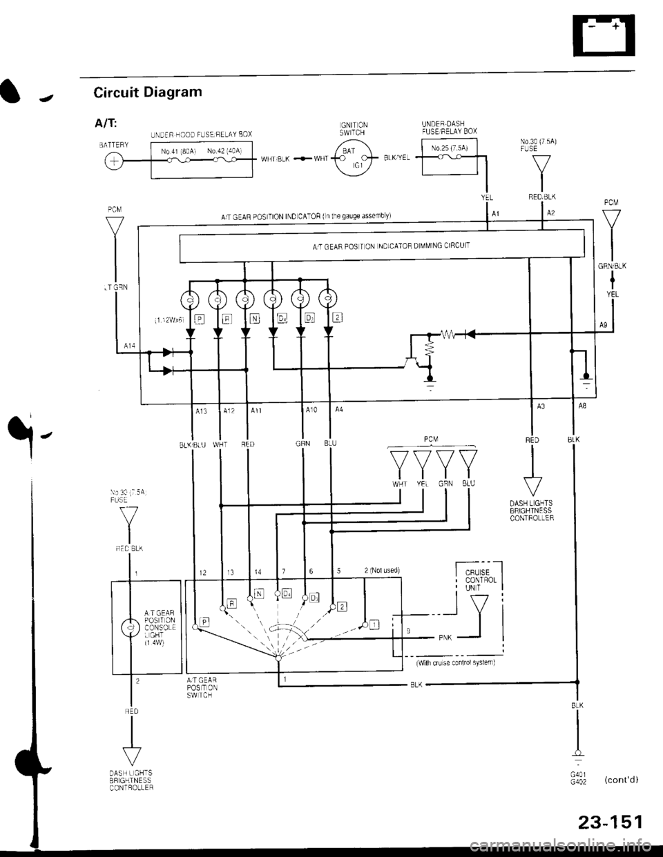
JCircuit Diagram
A/TUNDER HCCD FUSE BELAY BOX
PCi\4
V
I
I.T Gq
GNIT ONSW TCHTJNDEF OASH
'^a" fr-.-r^ """- *
-l
6l\
U__t- -t ir_i ;_P _+irh-
\:f
; h,:_
ArT GEAR POS TION IND CATOF (n lhegauge assembyl
A13412
YEL
f333{'*)
f7
IRED,ELKPCM
V
IGRNlBLK
I
l-
6LK 8LU
12
f7 f7 fl
ItlWHT YEL GFN
rl\4 l765 2 (Nol used)
{'}'}'1,
I
A._. --An i
t.--it-
Lrl9_PNK-
A'T GEARBLK
AIT GEAR POSTON NDLCA1ORD MM]NG CIRCUT
II
I
DASH L GHTSBRIGHTNESSCONTFOLLER
f7
ISLU\. -Ti i:5AFL]SE
V
IF:I BLK
I
l',
ll^,.,^,1L,-N pos r oN II(d].ONSCLEI
lYi:il |
Il--f'-
IRED
I
I
DASH L GHTSBB GHTNESSCONTFOLLER
BLK
I
oio,G402
23-151