1 page HONDA CIVIC 1996 6.G Workshop Manual
[x] Cancel search | Manufacturer: HONDA, Model Year: 1996, Model line: CIVIC, Model: HONDA CIVIC 1996 6.GPages: 2189, PDF Size: 69.39 MB
Page 1797 of 2189
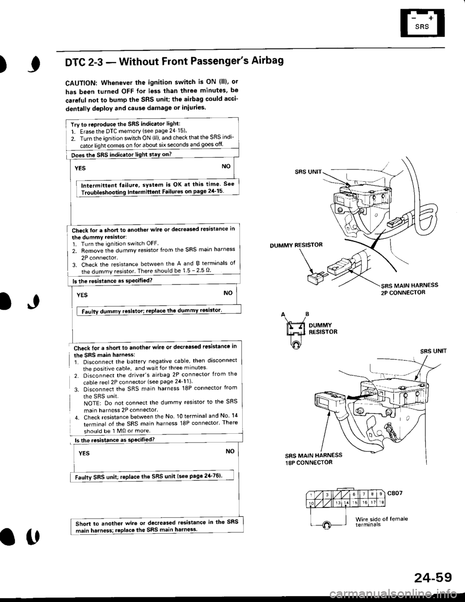
)DTC 2-3 - Without Front Passenger's Airbag
CAUTION: Whenever the ignition switch is ON (lll, ot
has been turned OFF for less than three minutes, be
careful not to bump thc SRS unit; the ailbag could acci-
dentally deploy and cause damage or iniuries.
Try to reproduce the SRS indicator light:
1. Erase the DTC memory tsee page 24 15).
2. Turn the ignition switch ON (ll), and check that the SRS indi-
cator light comes on for about six seconds and goes off
Ch6ck for a Short to another wile or decreased resistance in
the dummy resistor:1. Turn the ignitaon switch OFF.
2. Remove the dummy resistor from the SRS main harness
2P connector.
SRS UNIT
DUMMY RESISTOR
3. Check the resistance between the A and B terminals of
the dummy resistor. There should be 1-5 - 2.5 O.
Check for a short to another wile or decrea36d r6istance in
the SRS main harness:1. Disconnect the battery negative cable, then d'sconnect
the positive cable, and wait for three m inutes
2. Disconnect the driver's airbag 2P connector from the
cable reel 2P connector (see page 24-l l)
3. Disconnect the SRS main harness 18P connector from
the sRs unit.NOTE: Do not connect the dummy resistor to the SRS
main harness 2P connector.
4. Check resistance between the No lO terrninal andNo lil
terminal of the SRS main harness 18P connector' There
should be 1 M0 or more.
ls the resistance as
YES
SRS MAIN HARNESS
2P CONNECTOR
IJAB
ifti
|T'ti^i
DUMMYRESISTOR
SRS UNIT
SRS MAIN HARNESS18P CONNECTOR
24-59
Does the SRS indicator light staY on?
lntermittent failure, system is OK ai this time See
Int€rmittont Failures on page 2/a'15
ls the resistance as specifiod?
Faufly SRS unit; replace tho SRS unit l3ee page2+761'
Short to another wiro or decreased resistance in the SFS
main harness; replace the SRS main harne3s.
att
Page 1798 of 2189
Troubleshooting
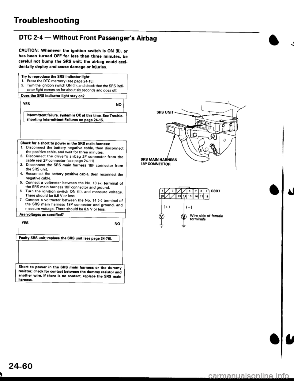
DTC 2-4 - Without Front Passenger's Airbag
CAUTION: Whenever the ignition switch is ON 0l). orhas been turned OFF for lsss lhan three minutes. becaretul not bump the SRS unit; the airbag could acci-dentally doploy and causo damage or iniuries.
Try to r€produc€ tho SRS indic.to. light:1. Erase the DTC memory (see page 24,15).2. Turn the ignition switch ON (ll), and check that the SRS indi-cator light comes on for about six seconds and go€s off.
Do€rthe SRS indicrtor light stay on?
NOrEs
lntormitteit t ilur., iyst m b OK at thb tim6. Sle Troubleshooling Intdmitt.nt Frilu.os on pag6 2+lS.
Check for a short to power in the SRS main h.rna3s:1. Disconnect the baftery negative cable, then disconnectthe positive cable, and wait for three minutes.2. Dlsconnect the driver's airbag 2p connector from thecable reel 2P connector (see page 24,11).3. Dlsconnect the SRS main harness l8p connector tromthe SRS unit.4. Beconnect the battory positiv€ cable, then reconnect thenegative cable.5. Connect a voltmeter between the No. lO (+) terminal ofthe SFS main hsrness 18P connector and qround.6. Turn the ignition switch ON {ll), and me-asure voltage.There should be 0.5 V or less.7. Connect a voltmeter between the No. 14 (+) terminal ofthe SRS main harness 18P connoctor and ground, andmeasure voltage. There should be 0.5 V or less.
A.e voltage. .3 spocifi.d?
YES NO
F.ulty SRS uniC .epla"" tl,. SnS unn l""" p"g" 2+7O:_l
Short to pow.r in tha SRS mlin harnc$ or tho dummyr*istor; chock lor contact bctwcen th. dummy r6ai3to. rndrnother wiro. lf there is no contrct, rcphcc the SRS msinhame3s.
SBS UNIT
SRS MAIN18P CONNECTOR
24-60
I
Page 1799 of 2189
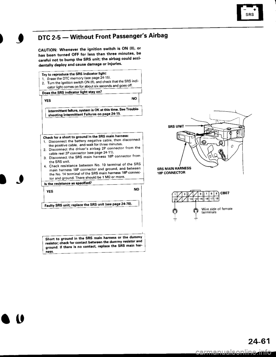
)DTC 2-5 - Without Front Passenger's Airbag
CAUTTON: Whenever the ignition switch is ON lll)' ol
has been turnsd OFF for less than three minutes' be
careful not to bump the SBS unit; the airbag could acci'
dentally deploY and Gause damage or iniuries'
Tru to .oproduce the SRS indic'tor light:
1 Erasethe DTC memory {see page 24 15)'
z. irin tfie ignition s.itch ON (ll), and check that the SRS indi-
iatoi ligiricomes on for about six seconOs and goes otf
Does the SRS indic.tor light stay on7 |
NOYES
tn---t",-in"m l"itrt", "v"tem is oK at thb lim' seo Troubl'-
3hooling Intormitt6nt Failures on pago 2+15'
ffih",n"""'i. oi""onn""t ttte u"tt"ry negative cable' then disconnect
the Dositive dable, and wait lor th ree mrnutes'
z. 6i"J-"""a tt'" driver's airbag 2P connector {from the
cable reel 2P connector (see page 24_11)'
s. b]""onn""t,f'" SFS main harness 18P connector from
the SRS unit.
L di"lfi""i"on." between No lo terminal of the sRS
main harness 18P connector and ground and between
iie t'lo. t a terminat of the SRS main harn€ss 18P connec-
I tor and ground There should be 1 Mo or more'
I btheresistanceasso444g14�._���._��
NOYES
-Faulty sRs unit; ,epltce the sRs unit (see page 2+761'
SRS UNIT
SRS MAIN HARNESS
18P CONNECTOR
IJ
ness,
6lort to sround in tho sRS main harness or the dummY
i""i"toi; "-ft""* fot "ont.ct bdtwo€n the dumTI Iesbt9r.and
li"r"J. n irt"t" is no contact. r6pl'co the sRs mtin h6i'
24-61
ott
Page 1800 of 2189
Troubleshooting
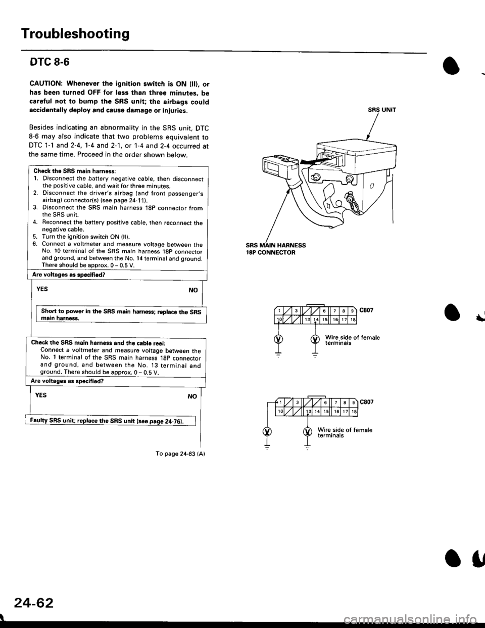
DTC 8-6
CAUTION: Whonover the ignition switch is ON lll), or
has been turned OFF for less than thro€ minutes, be
careful not to bump th6 SRS unit; the airbags couldaccidentally deploy and cause damage or iniuries.
Besides indicating an abnormality in the SRS unit, DTC
8-6 may also indicate that two problems equivalent to
DTC 1-l and 2-4, 1-4 and 2-1, ot 1-4 and 2-4 occurred at
the same time. Proceed in the order shown below.
SRS MAIN HARNESS18P CONNECTOR
\
24-62
Check th. SRS main harn6$:1. Disconnect the battery negative cable, then disconnectthe positive cable, and wait for three minutes.2. Disconnect the driver's airbag (and front passenger,sairbag) connector(s) {see page 21-111.3. Disconnect the SRS main harness 18P connector fromrhe sRS unit.4. Reconnect the battery positive cable, then reconnect thenegative cable.5. Turn the ignition switch ON (ll).6, Connect a voltmeter and measure voltage botween theNo. 10 terminal of the SRS main harness 1BP connectorand ground, and betlveen the No. l{ terminal and qround.Th6re should be aoDrox. 0 - 0.5 V.
Aro voltages as spacified?
NOYES
Sho.t to power in tho SRS mrin hamoss; rsplace th6 SRSmain haanac3.
Chacl the SRS main hrrne*s and the cabl. reel:Connect a voltmeter and measure voltage between theNo. 1 terminal of the SRS main harness 18p connectorand ground, and between the No. 13 terminal andground. There should be approx. 0 - 0.5 V.
Are voltages o3 specilied?
YES
SRS unit; replace the SRS unit lse6 page 2+76).
NO
To page 24-63 (A)
o1,
Page 1801 of 2189
,)
IJ
t,
From page 24'62 (A)
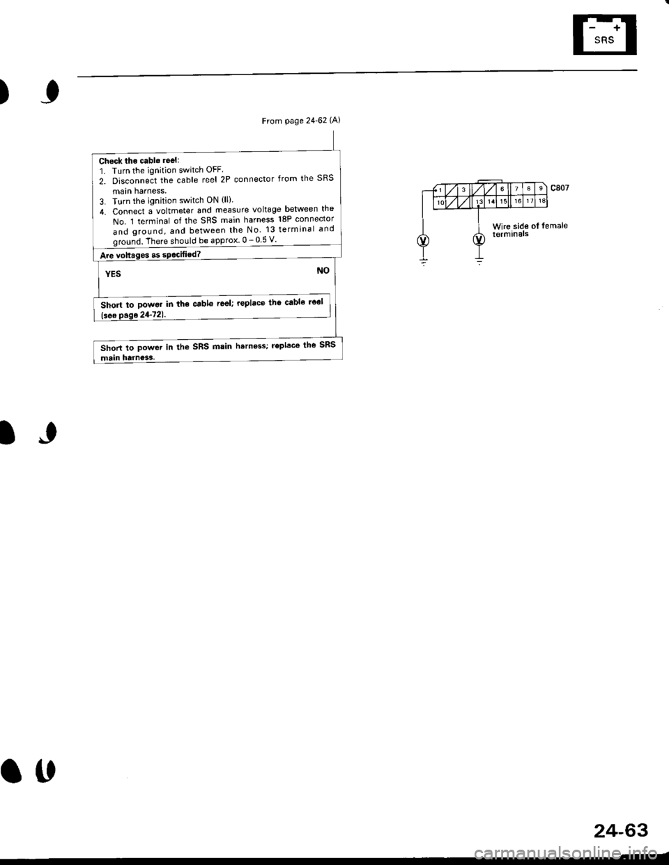
Check the cable reel:
1. Turn the ignition switch OFF
2. Disconneit the cable reel 2P connector from the SRS
maln harness,
3. Turn the ignition switch ON {ll}
4. Connect a voltmeter and measure voltage between the
No. 1 terminal of the SRS main harness 18P connector
and ground, and between the No 13 terminal and
ground. There should be approx. 0 - 0.5 V'
Are vohtg6 as specifi"dT -
YESNO
Short to powor in the cabto reel; replace thg cable rool
(see page 24'721.
Short to powet in the SRS main h.rness; replace the SRS
main harness.
24-63
Page 1802 of 2189
Troubleshooting
DTC 9-2
CAUTION: Whenever the ignition switch is ON 0l), ofhas been turned OFF lor lass than three minutes, becareful not to bump the SRS unit; the airbag(s) couldaccidentally deploy lnd caqse damage or iniuries.
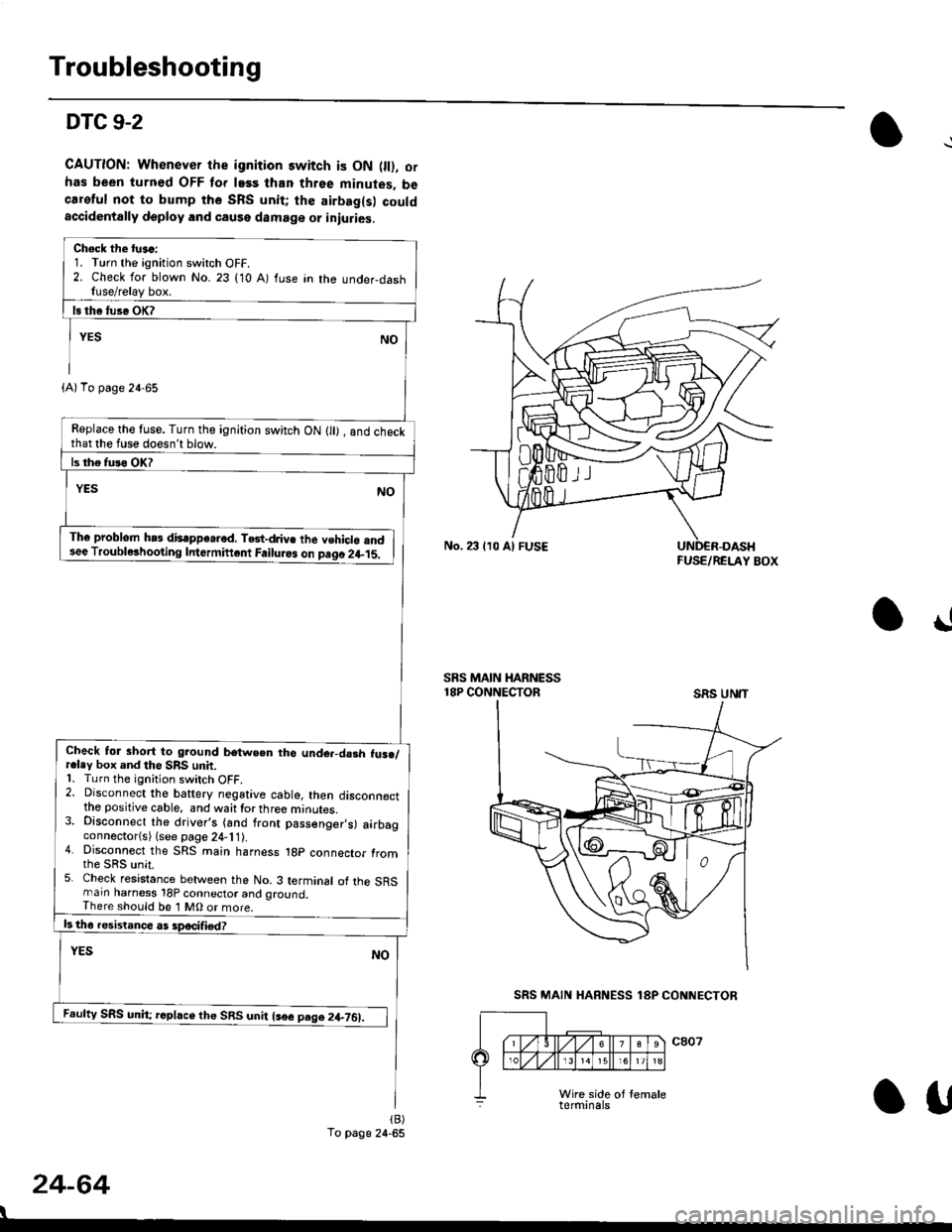
Check the tu.c:1. Turn the ignition switch OFF.2. Check for blown No. 23 (10 A) fuse in the under,dashfuse/relay box.
Replace the tuse. Turn the ignition switch ON lll) , and checkthat the fuse doesn't blow.
Th6 problem hs3 disappe.rod, TGt-dJiv€ the vehiclo and3ee Troublerhooting Intermiftcnt Failuro3 on paqo 2l-15.
Check tol short to ground betwe.n tho unde.-da3h fus./r.ley box and the SRS unit.1. Turn the ignition switch OFF.2. Disconnect the baftery negative cable, then disconnectthe positive cable, and waittorthree minutes.3. Disconnect the driver's (and front passenger,s) airbagconnector(s) (see page 24-11).4. Disconnect the SRS main harness 1gp connector fromthe sRs unit.5. Check resistance between the No. 3 terminal of the SRSmarn harness 18P connector and ground,There should be 1 MO or more.
Feufty SRS unh; rcphce the SRS unit lsee pag.2+761.
(A)To page 24-65
To page 24-65
No. 23 lr0 Al FUSEFUSE/RELAY BOX
!
SRS MAIN HARNESS18P CONNECTORSRS UN'T
24-64
I
SRS MAIN HARNESS 18P CONNECTOR
Otf
Page 1803 of 2189
)
FUSE/BELAY BOX
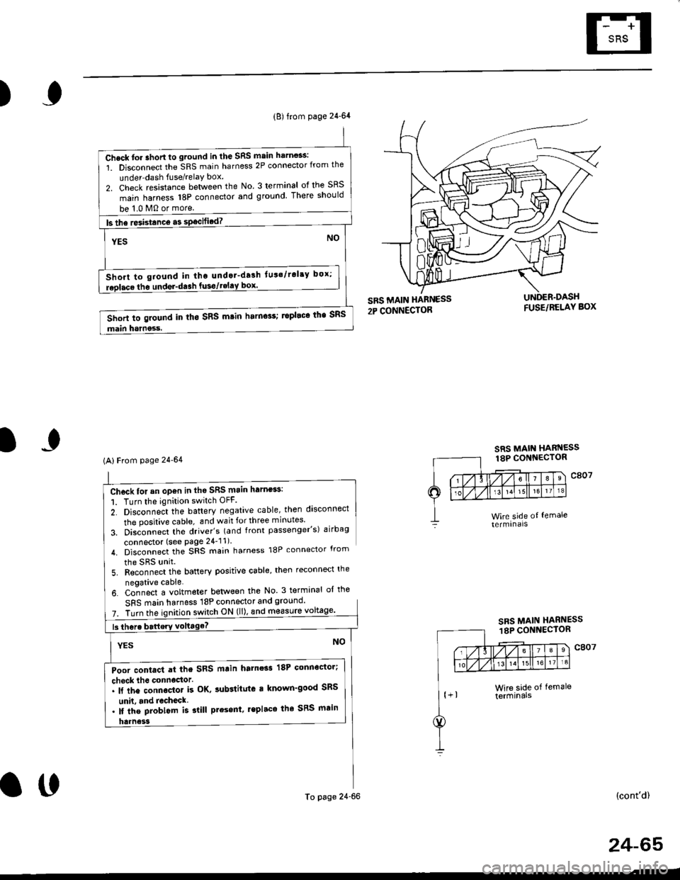
Chcck for an op€n in th6 SRS main harness:
1. Turn the ignition switch OFF.
2. Disconne;t the battery negative cable, then disconnect
the positive cable, and wait for three minutes'
3. Disconnect tho driver's (and front passenger's) airbag
connector (see Page 24'11).
4. Disconnect the SRS main harness 18P connector from
the SRS unit
5. Reconnect the battery positive cable, then reconnect the
neoative cable.
6. Co-nnect a voltmeter betlveen the No 3 terminal ol the
SFS main harness 18P connector and ground'
7. Turn theswitch ON (ll), and m€asure
(cont'd)
(B) from page 24-64
Check tor ahort to ground in the SRS main harn$s:
1. Disconnect the SRS main harness 2P connector from the
under-dash fuse/relaY box.
2. Check resistance between the No. 3 terminal of the SRS
main harness 18P connector and ground There should
be 1.0 M0 or more.
ls the re3istance a3 specified? -
NOYES
Short to giound in tho undot-drlh lut'/rol'y box;
replace the undel-da3h fusgtgEl!9l--------.-
Short to ground in tho SRS m.in harn$s; ropleco the SRS
main harness.
(AlFrom page 24'64
Poor contact at the SRS main harnoss 18P connoctor;
check lho connoctor.. ll the connector k OK, sub3titute r known'good SRS
unh. and recheck. lf the problom is slill present, lepl.ce the SRS main
To page 24-66
SRS MAIN HARNESS18P CONNECTOR
o0
24-65
Page 1804 of 2189
Troubleshooting
DTC 9-2 (cont'dl
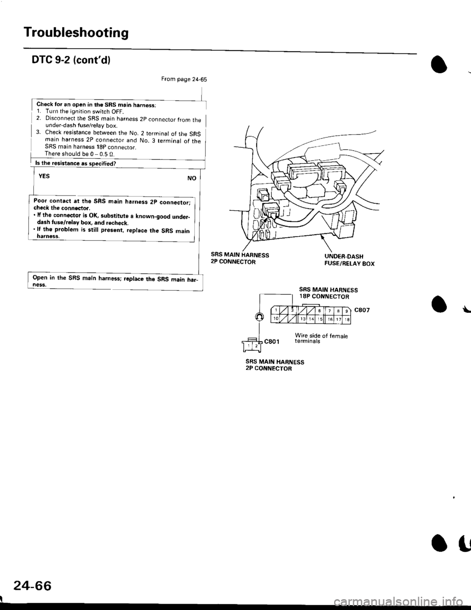
2- Disconnect the SRS rnain harness 2p connector lrom theunder-dash fuse/relay box.3- Check resistance between the No. 2 terminal of the SRSmain harness 2P connecior and No. 3 terminal of theSFS main harness 18P connector_
Poor contact at the SRS main ha.ness 2p connector;check the connecto... lf the connector is Ol(, sub3titute a known-good under-dash tuse/r€lay box, and recheck.'lt tho problem is still present, replece the SRS main
Open in the SBS main harness; replace the SRS main har_ness,
SRS MAIN HARNESS2P CONNECTOR
24-66
I
\
From page 24-65
Chock tor an open in th€ SRS main hern€ss:1. Turn the ignition switch OFF.
There should be 0 0.5 0
SRS MAIN
SRS MAIN HARNESS18P CONNECTOR
o!
Page 1808 of 2189
Airbag
Disposal
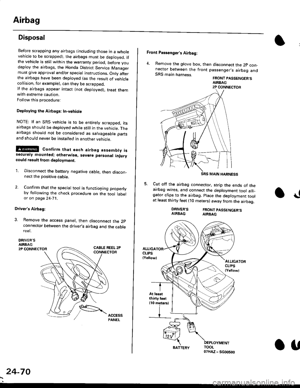
Before scrapping any airbags (including those in a wholevehicle to be scrapped), the airbags must be deployed. lfthe vehicle is still within the warranty period, before youdeploy the airbags, the Honda District Service Managermust give approval and/or special instructions. Onlv afterthe airbags have been deployed (as the result of vehiclecollision, for example), can they be scrapped.lf the airbags appear intact (not deployed). treat themwith extreme caution.
Follow this p.ocedure:
Deploying the Airbags: In.vehiclo
NOTE: lf an SRS vehicle is to be entirely scrapped, itsairbags should be deployed while still in the vehicle. Theairbags should not be considered as salvageable partsand should never be installed in another veh;cle.
!@ confirm thst oach airbag assembty issecurely mounted; otharwiso. sev€re personal iniurycould result lrom deployment.
1. Disconnect the baftery negative cable, then discon_nect the positive cable.
2. Confirm that the special tool is functioning properlyby following the check procedure on the tool labelor on page 24-'l'l .
Driver's Airbag:
3. Remove the access panel, then disconnect the 2pconnector between the driver,s airbag and the cablereet.
DRIVER'SAIRBAG2P CONNECTOR
24-70
BATTERY.U
Front Passenger's Airbag:
4. Remove the glove box, then disconnect the 2p con-nector between the lront passenger,s airbag andSRS main harness.FRONT PASSENGER'SAIREAG2P CONNECTOB
SRS MAIN HARNESS
Cut off the airbag connector, strip the ends of theairbag wires, and connect the deployment tool alli_gator clips to the airbag. place the deployment toolat least thirty feet (10 meters) away from the airbag.
a!
DRIVER'SAIRBAGFRONT PASSENGER'SAIRBAG
ALLIGACLIPS(Yellow)ALLIGATORCLIPS{Yellowl
At loastthiny toet(10 metorsl
Page 1809 of 2189
E-
)I
Connect a 12 volt battery to the tool:
. lf the green light on the tool comes on, the aar-
bag igniter circuit is defective and cannot deploy
the airbag. Go to Damaged Airbag Special
Procedure.
. lf the red light on the tool comes on, the airbag is
ready to be deployed.
Push the tool's deployment switch. The airbag
should deploY (deployment is both highly audible
and visible; a loud noise and rapid inflation of the
bag, followed by slow deflation).
. lf the airbags deploy and the green light on the
tool comes on. continue with this procedure.
. l{ an airbag doesn't deploy, yet the green light
comes ON, its igniter is defective. Go to Dam-
aged Airbag Special Procedure.
!!@ During doployment, the airbag sssom'
bly can become hot enough to buln you. Wait thir'
ty minutes aftsr deployment belore touching tho
assembly.
Dispose of the complete airbag assembly. No part
of it can be reused. Place it in a sturdy plastic bag,
and seal it securelY,
CAUTION:
. Wear a fsce shield and gloves when handling a
deployed airbag.
. Wash your hands and rinse them well with
wat6r after handling. deployed airbag.
t('
24-71
7.
AIRAAG
Doploying th6 Airbag: Out-of-vehicle
NOTE: lf an intact airbag has been removed from a
scrapped vehicle. or has been found defective or dam-
aged during transit, storage or service, it should be
deployed as follows:
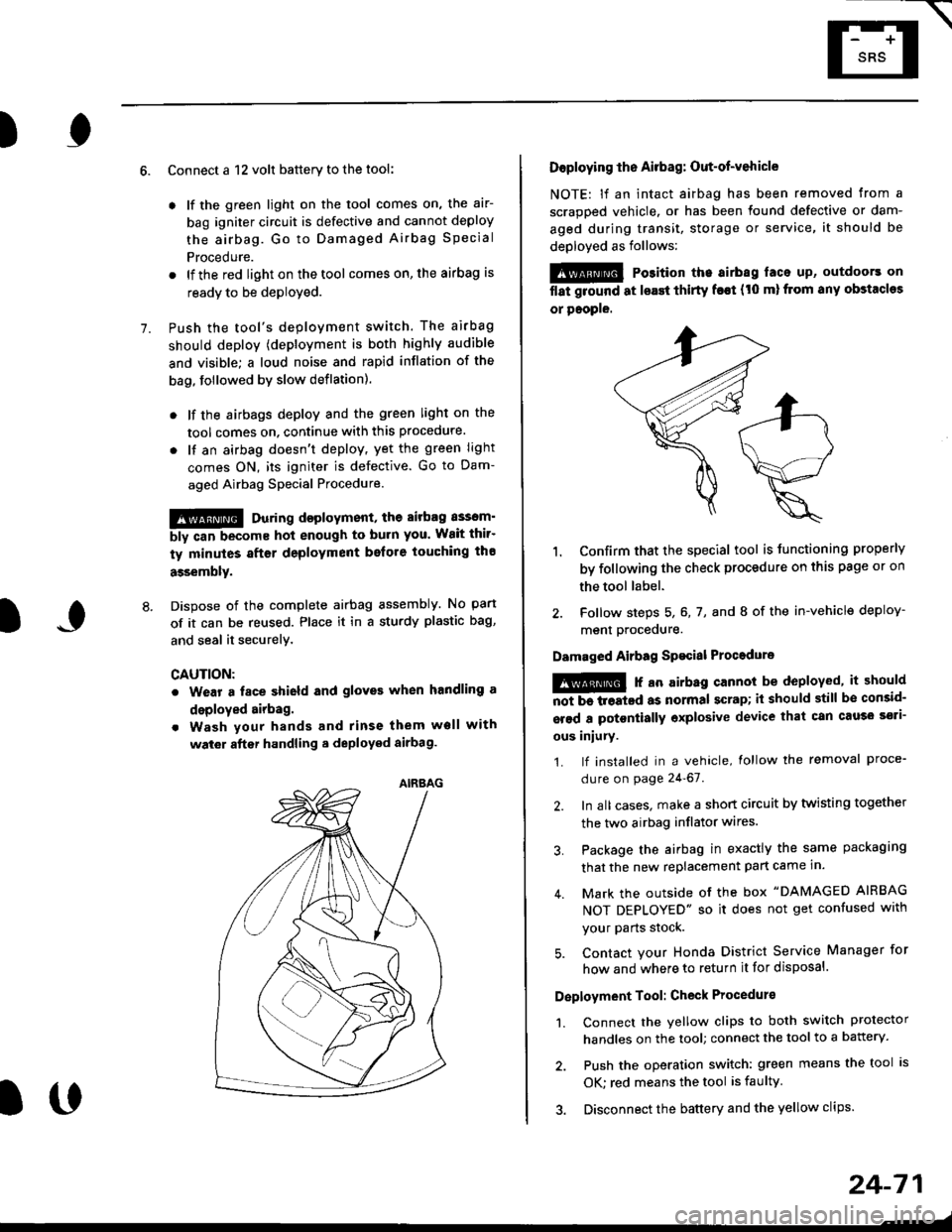
@ Po3ition the airbag laca up, outdoors on
flat ground at lsast thirty f€€t (t0 ml from any obstacles
or people.
1. Confirm that the special tool is tunctioning properly
by following the check procedure on this page or on
the tool label.
2. Follow steps 5, 6, 7, and I of the in-vehicle deploy-
menl Drocequre.
Damaged Airbag Spacial Procedure
!@ r an airb.g cannot be deployed, it should
iiiTi-treatcd as normal scrap; il should still be consid-
srsd a potontially oxplosive device that can cau3o ssti-
ous iniury.
1. lf installed in a vehicle, lollow the removal proce-
dure on page 24-67.
2. In all cases. make a short circuit by twisting together
the two airbag inflator wires.
3. Package the airbag in exactly the same packaging
that the new replacement part came in.
4. Mark the outside of the box "DAMAGED AIRBAG
NOT DEPLOYED" so it does not get confused with
your Parts stock.
5. Contact your Honda District Service Manager for
how and where to return it for disposal.
Deployment Tool: Check Procedur€
1. Connect the yellow clips to both switch protector
handles on the tool; connect the tool to a battery.
2. Push the operation switch: green means the tool is
OK: red means the tool is faulty
3. Disconnect the battery and the yellow clips.