Speed sensor HONDA CIVIC 1996 6.G Manual Online
[x] Cancel search | Manufacturer: HONDA, Model Year: 1996, Model line: CIVIC, Model: HONDA CIVIC 1996 6.GPages: 2189, PDF Size: 69.39 MB
Page 792 of 2189
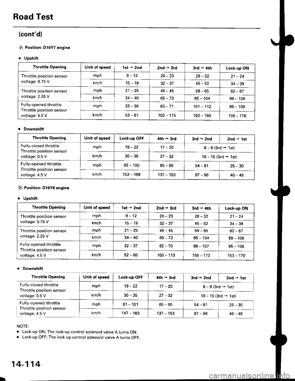
Road Test
(cont'dl
.91 Position: Dl6Y7 engine
. Upshift
Throttle OpeningUnit of speedlst + znd2nd * 3rd3rd t 4thLock-up ON
Throttle position sensor
voltage: 0.75 V
mph9-1220-2328-3221 -24
km/h15-1932-3745-5234-39
Throttle position sensor
voltage:2.25 V
mph40-4562-67
km/h34-4095 - 10499 - 't08
Fully-opened throttle
Throttle position sensor
voltage: 4.5 V
mph33-38101 - 't1299 - 109
km/h53-61102-115163 - 180'159 - 176
Downshift
Throftle OpeningUnit of speedLock-up OFF'lth + 3rd3rd + 2nd2nd t lst
Fully closed throttle
Throttle position sensor
voltage: 0.5 V
mph't9 - 2217 -206-9(3rd+lst)
km/h30-3527 -3210 - 15 (3rd + 1st)
Fully-opened throttle
Throttle position sensor
voltage: 4.5 V
mpn95 - 10585-9554-6125-30
km/h153 - 169137 - 15387-9840-48
-q1 Position: DI6YB engine
. Upshift
Downshift
NOTE:
. Lock-up ON: The lock-up control solenoid valve A turns ON.. Lock-up OFF: The lock-up control solenoid valve A turns OFF.
Throttle OpeningUnit of speedlst + 2nd2nd - 3rd3rd + 4thLock-up ON
Throftle position sensor
voltage: 0.75 V
mph9-1220-232A-3221 -24
km/h15-1932-3745-5234-39
Throttle position sensor
voltage:2.25 V
mpn21 -2540-4559-65
km/h34-4095 - 10499 - 108
Fully-opened throttle
Throttle position sensor
voltage: 4.5 V
mph32-3762 -7096 - 10795 - 106
km/h52-60100 - 113't55 - 112't53 - '�170
Throttle OpeningUnit ot speedLock-up OFF'lth + 3rd3rd+2nd I 2nd+lst
Fully-closed throttle
Throttle position sensor
voltage: 0.5 V
mph19-2217 -206-9(3rd+ 1st)
km/h30-3527 -32l0 - 15 (3rd + lst)
Fully opened throttle
Throttle position sensor
voltage: 4.5 V
mpn91 - 10154-61 25-30
km/h'147 - 163137 - 15387-98 I 40-48
l.
14-114
Page 800 of 2189
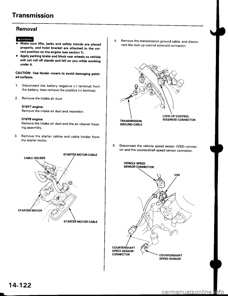
Transmission
Removal
@Maks sure lifts, iacks and safety stands are placedproperly, and hoist bracket ate aftached to the cor_rec{ position on the engine lsee section 1).Apply parking brake and block rear whoels so vehiclewill not roll off stands and fall on you while workingunder it.
CAUTION: Use tender covers to avoid damaging paint-ed surfaces.
1, Disconnect the battery negative (_) terminal fromthe battery, then remove the positive (+) terminal.
2. Remove the intake air duct.
D16Y7 engins:
Remove the intake air duct and resonator.
D16Y8 engine:
Remove the intake air duct and the air cleaner hous-ing assembly,
3. Remove the starter cables and cable holder fromthe starter motor.
MOTOR CABLE
MOTOR CABLE
14-122
4. Remove the transmission ground cable, and discon_nect the lock-up control solenoid connector.
LOCK.UP CONTROLSOLENOID CONNECTOR
5, Disconnect the vehicle speed sensor (VSS) connec_tor and the countershaft speed sensor connector.
VEHICLE SPEED
Page 801 of 2189
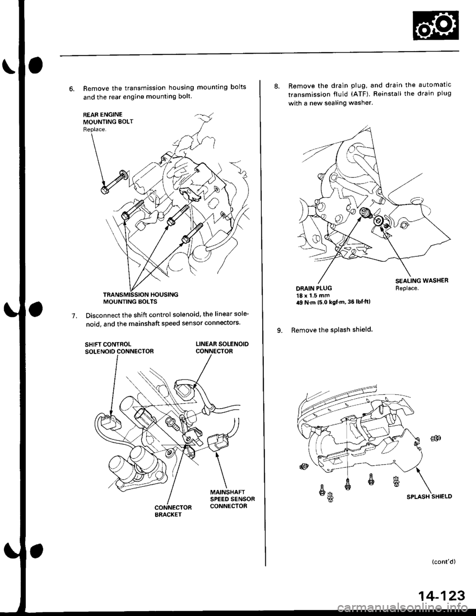
6. Remove the transmission housing mounting bolts
and the rear engine mounting bolt.
Disconnect the shift control solenoid, the linear sole-
noid, and the mainshaft speed sensor connectors'7.
SHIFT CONTROLSOLENOID CONNECTORLINEAR SOLENOIDCONNECTOR
MOUNTING BOLTS
BRACKET
8. Remove the drain plug, and drain the automatic
transmission fluid (ATF). Reinstall the drain plug
with a new sealing washer.
DRAIN PLUG18 x 1.5 mm'9 N m t5 o kgf'm' 36 lbf'ft|
9. Remove the splash shield.
Replace.
SPLASH SHIELD
{cont'd)
14-123
Page 805 of 2189
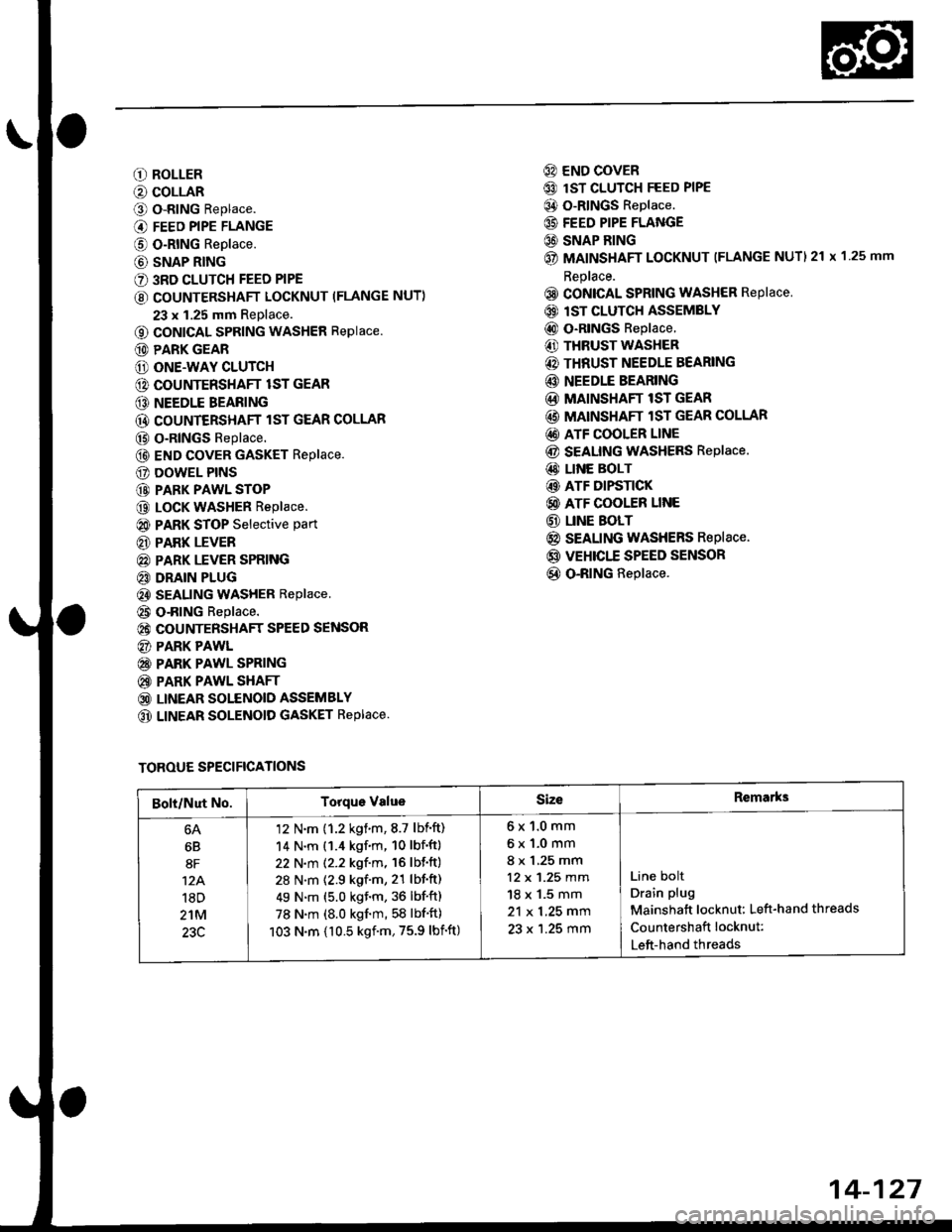
O ROLLER
O COLLAR
O o-RING Replace.
@ FEED PIPE FLANGE
@ O-RING Replace.
@ SNAP RING
€) 3RD CLUTCH FEED PIPE
€) COUNTERSHAFT LOCKNUT (FLANGE NUT)
23 x 1.25 mm Replace.
o coNlcAL SPRING WASHER Replace.
@ PARK GEAR
@ ONE.WAY CLUTCH
@ COUNTERSHAFT lST GEAR
@ NEEDLE BEARING
@ COUNTERSHAFT lST GEAR COLLAR
@ o-RlNGs Replace.
@ END covER GASKET Replace.
E) DOWEL PINS
@ PARK PAWL STOP
@ LocK WASHER Replace.
@ PARK STOP Selective part
€D PARK LEVER
@ PARK LEVER SPRING
€D DRAIN PLUG
€) SEALING WASHER Replace
@ o-RING Replace.
@ COUNTERSHAFT SPEED SENSOR
@) PARK PAWL
@ PARK PAWL SPRING
@ PARK PAWL SHAFT
@ LINEAR SOLENOID ASSEMBLY
@ LINEAR SOLENOID GASKET REPIACE.
@) END COVER
@ lsT CLUTCH FEED PIPE
@ O-RINGS Replace.
@ FEED PIPE FLANGE
C) SNAP BING
@ MAINSHAFT LOCKNUT (FLANGE NUTI 21 x 1 25 mm
Replace.
@ CONICAL SPRING WASHER RePlace
@) lST CLUTCH ASSEMBLY
@ o-RlNGs Replace.
€) THRUST WASHER
@) THRUST NEEDLE BEARING
@ NEEDLE BEARING
@ MAINSHAFT lST GEAR
@ MAINSHAFT lST GEAR COLLAR
@) ATF COOLER LINE
@ SEAUNG WASHERS Replace.
@ LINE BOLT
@ ATF DIFSTICK
@ ATF COOLER LINE
@ UNE BOLT
@ SEALING WASHERS Replace.
@ VEHICTT SPEED SENSOR
@ O-RING Replace.
TOROUE SPECIFICATIONS
Bolt/Nut No.Torque ValueSizeRemarks
6B
8F
12A.'l8D
2'tM
23C
'12 N'm (1.2 kgim,8.7 lbift)
14 N.m (1.4 kgf.m, 10 lbf'ft)
22 N.m (2.2 kgf.m, 16 lbf'ft)
28 N.m (2.9 kgf.m, 21 lbf'ft)
49 N.m (5.0 kgf.m, 36 lbf'ft)
78 N.m (8.0 kgf'm, 58 lbf'ft)
103 N.m {10.5 kgf'm,75.9 lbift)
6x1.0mm
6x1.0mm
8 x 1,25 mm
12 x 1.25 mm
18 x 1.5 mm
21 x 1.25 mm
23 x 1.25 mm
Line bolt
Drain plug
Mainshatt locknut: Left-hand threads
Countershaft locknut:
Left-hand threads
14-127
Page 807 of 2189
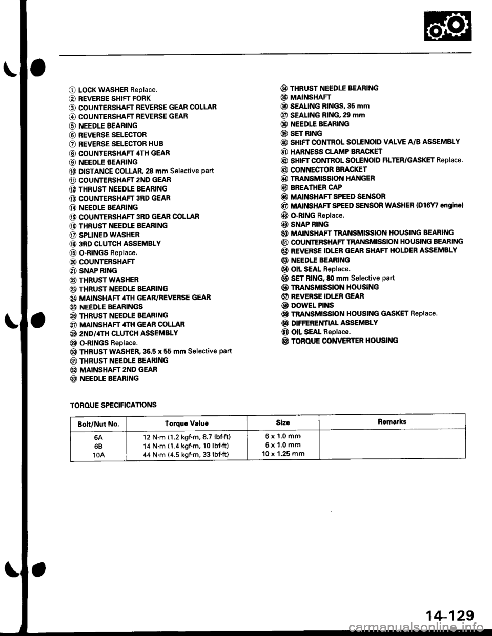
O LocK WASHER Replace,
O REVERSE SHIFT FORK
O COUNTERSHAFT REVERSE GEAR COLLAR
G) COUNTERSHAFT REVERSE GEAR
@ NEEDLE BEARING
@ REVERSE SELECTOR
O REVERSE SELECTOR HUB
@ COUNTERSHAFT 4TH GEAR
O NEEDLE BEARING
@ DISTANCE GOLLAR, 28 mm Selective part
O COUNTERSHAFT 2ND GEAR
@ THRUST NEEDIE BEARING
@ COUNTERSHAFT 3RD GEAR
@ NEEDLE BEARING
@ COUNTEBSHAFT 3RD GEAR COLLAR
@ THRUST NEEDLE BEAFING
O SPLINED WASHER
@ 3RD CLUTCH ASSEMBLY
@ O-RtNGs Replace.
@ COUNTERSHAFT
@ SNAP RING
@ THRUST WASHER
€) THRUST NEEDTE BEARING
@} MATNSHAFT 4TH GEAR/REVERSE GEAR
@i NEEDLE BEARINGS
@ THRUST NEEDLE EEARING
@) MAINSHAFT 4TH GEAR COLLAR
@ 2ND/4TH CLUTCH ASSEMBLY
@ o-RlNGs Replace.
@ THRUST WASHER,36.5 x 55 mm Sel€ctive part
@ THRUST NEEDLE BEARING
@ MAINSHAFT zND GEAR
@ NEEDLE BEARING
@ THRUST NEEDLE BEARING
@ MAINSHAFI
@ S€ALING RINGS, 35 mm
@ SEALING RING,29 mm
@} NEEDIE BEARING
@ SET RING
@ sHrFT CONTROL SOLENOID VALVE A/B ASSEMSLY
@ HARNESS CLAMP BRACKET
@ SHIFT COI,ITROL SOI"ENOID FILTER/GASKET Replace.
@ CONNECTOR BFACKET
@D TNANSMISSION HANGER
@ BREATHER CAP
@ MAINSHAFT SPEED SENSOR
@ MATNSHAFT SPEED SENSOR WASHER {Dl6Y' ongine}
@ O-RING Replace.
@ SNAP RING
@ MAINSHAFT TRANSMISSION HOUSING BEARING
@ OOUNIERSHAFT TRANSMISSION HOUSING BEARING
@ REVERSE IDLER GEAR SHAFT HOLDER ASSEMBLY
@ NEEDI.E BEARING
@ olL SEAL Replace.
@ SET RING, fll mm Selective part
@ rnANsMrssloN HouslNG
@ REVERSE IDI."ER GEAR
@ DowEL PINS
@ TRANSMISSION HOUSING GASKET Replace.
@ DIFFERENfIAL ASSEMBLY
@ OIL SEAL Replace.
@ TOROUE CONVERTER HOUSING
TOROUE SPECIFICANONS
Boh/Nut No.Torquo valueSizeRomarks
6B
10A
12 N.m {1.2 kgf.m,8.7 lbf.ft)
14 N.m (1.4 kgf'm, 10lbf'ft)
44 N.m (4.5 kgf.m, 33 lbf'ft)
6x1.0mm
6x1.0mm
10 x 1.25 mm
14-129
Page 812 of 2189
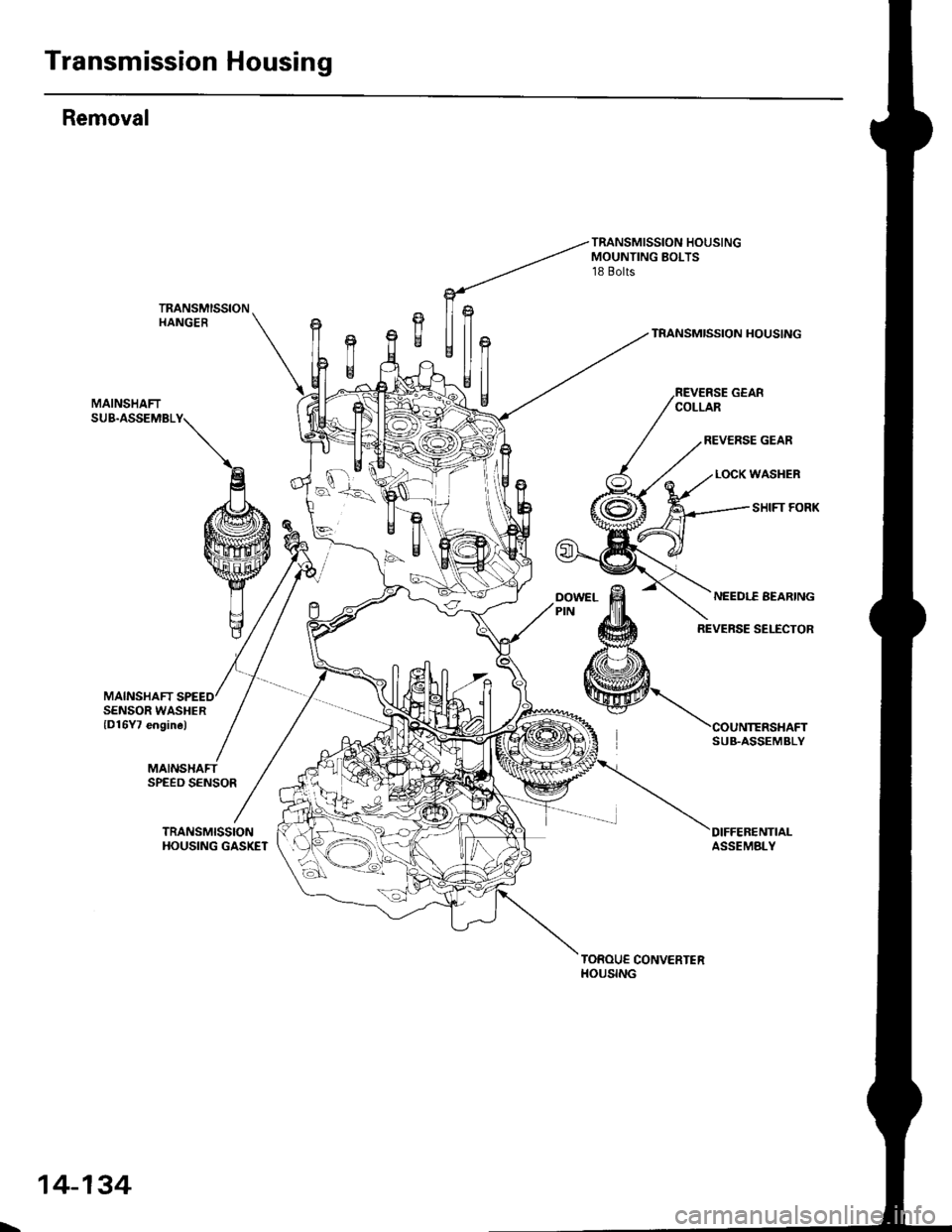
Transmission Housing
Removal
MAINSHAFT
TRANSMISSION HOUSINGMOUNTING BOLTS18 Bolts
TRANSMISSIONHANGERTRANSMISSION HOUSING
MAINSHAFTSUB.ASSEMBLY
SENSOR WASHERlD16Y7 engine)
MAINSHAFTSPEED SENSOR
TRANSMISSIONHOUSING GASKETDIFFEBENTIALASSEMBLY
TOROUE CONVERTERHOUSING
SUB.ASSEMBLY
L,
14-134
Page 856 of 2189
![HONDA CIVIC 1996 6.G Manual Online Transmission
_\,]ffil
Reassembly (contd)
TRANSMISSIONHANGER
MAINSHAFTSUB.ASSEMBLY
*
Ufln
$*U ./
TRANSMISSION HOUSINGMOUNTING BOLTS10 x 1.25 mm4{ N.m {4.5 kg{.m,33 lbI.ft)
TRANSMISSION HOUSING
REVER HONDA CIVIC 1996 6.G Manual Online Transmission
_\,]ffil
Reassembly (contd)
TRANSMISSIONHANGER
MAINSHAFTSUB.ASSEMBLY
*
Ufln
$*U ./
TRANSMISSION HOUSINGMOUNTING BOLTS10 x 1.25 mm4{ N.m {4.5 kg{.m,33 lbI.ft)
TRANSMISSION HOUSING
REVER](/img/13/6068/w960_6068-855.png)
Transmission
_\,]ffil
Reassembly (cont'd)
TRANSMISSIONHANGER
MAINSHAFTSUB.ASSEMBLY
*''
Ufln
$*U ./
TRANSMISSION HOUSINGMOUNTING BOLTS10 x 1.25 mm4{ N.m {4.5 kg{.m,33 lbI.ft)
TRANSMISSION HOUSING
REVERSE GEARCOLLAR
REVERSE GEAR
LOCK WASHER
SHIFT FORK
MAINSHAFT SPEEDSENSOR WASHER(D16Y7 engine)
MAINSHAFT
COUNTERSHAFTSUB.ASSEMBLY
OIFFER€NTIALASSEMBLY
SPEED
TRANSMISSIONHOUSING GASKET
TOROUE CONVERTERHOUSING
14-178
Page 857 of 2189
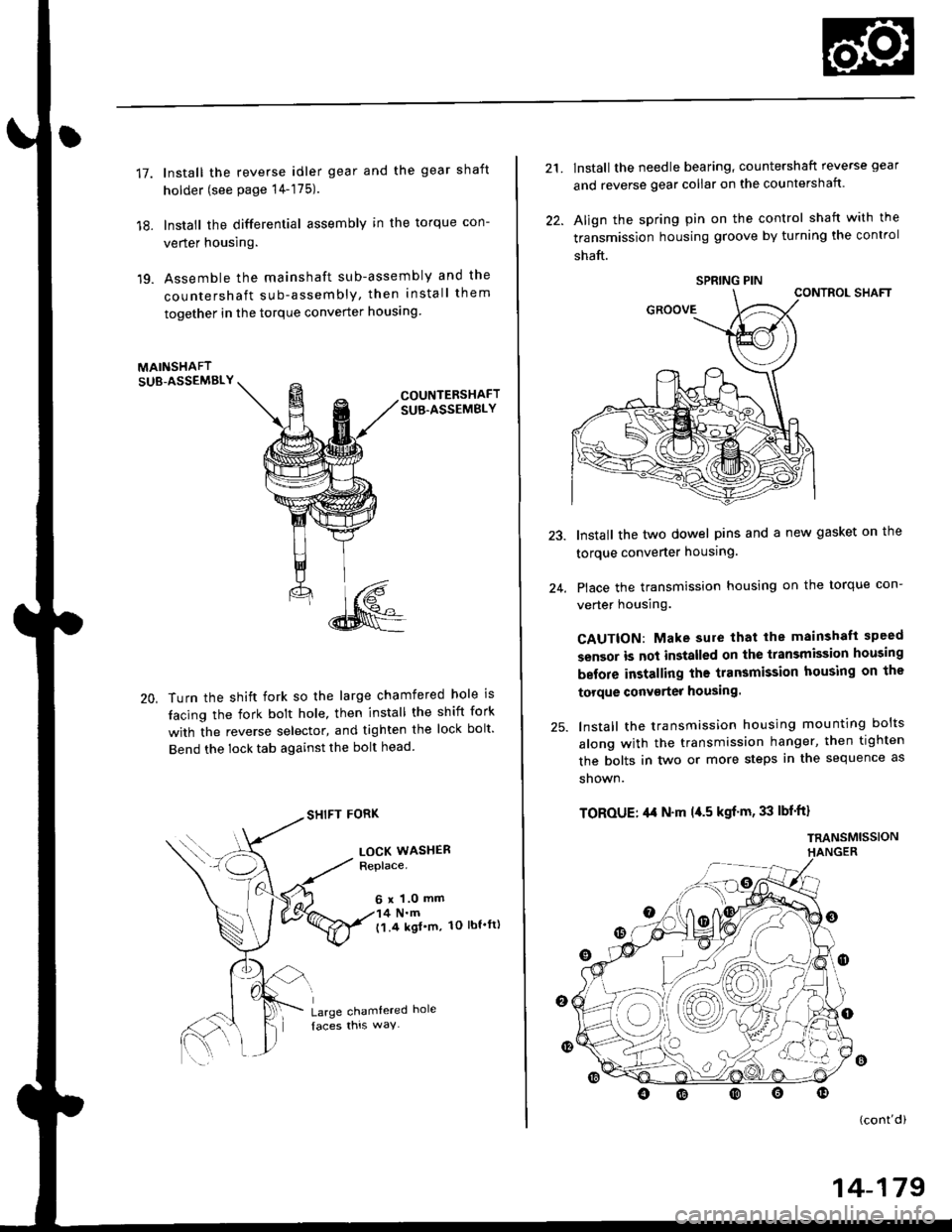
17.
18.
19.
lnstall the reverse idler gear and the gear shaft
holder (see page 14-175).
lnstall the differential assembly in the torque con-
verter housing.
Assemble the mainshaft sub-assembly and the
countershaft sub-assembly, then install them
together in the torque converter houslng
MAINSHAFTSUB-ASSEMBLY
20,
COUNTERSHAFTSUB.ASSEMBLY
Turn the shift fork so the large chamfered hole is
tacing the fork bolt hole, then install the shift fork
with the reverse selector, and tighten the lock bolt'
Bend the lock tab against the bolt head
SHIFT FORK
LOCK WASHERReplace.
6 x 1.0 mm4 N.m('l.4 kgl'm, 1O lbt'ft)
Large chamtered hole
21.
22.
lnstall the needle bearing, countershaft reverse gear
and reverse gear collar on the countershaft.
Align the spring pin on the control shaft with the
transmission housing groove by turning the control
shaft.
CONTROL SHAFT
Install the two dowel pins and a new gasket on the
torque converter housing.
Place the transmission housing on the torque con-
verter housing.
CAUTION: Make sure that lhe mainshaft speed
sensor is not installed on the transmission housing
before installing the transmission housing on the
torque conv€rter housing.
lnstall the transmission housing mounting bolts
along with the transmission hanger, then tighten
the bolts in two or more steps in the sequence as
shown.
TOROUE: ,l,t N'm l{.5 kgf'm, 33 lbf'ft}
TRANSMISSIONHANGER
24.
o
(cont'di
SPRING PIN
14-179
Page 863 of 2189
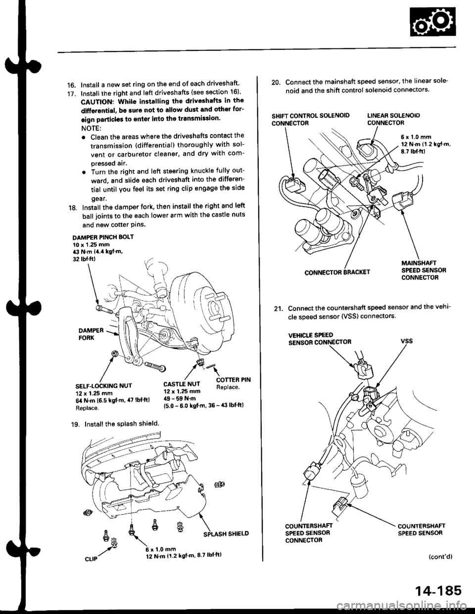
16. Install a new set ring on the end of each driveshaft'
17. Installthe right and left driveshafts (see ssction 16)
CAUTION: Whil6 installing the driveshafE in the
diffarential, be surs not lo allow du3t and othor for-
eign particl€s to enler into the transmission.
NOTE:
. Clean the areas where the driveshafts contact the
transmission (differential) thoroughly with sol-
vent or carburetor cleaner, and dry with com-
pressed air.
. Turn the right and left steering knuckle fully out-
ward, and slide each driveshaft into the differen-
tial until you feel its set ring clip engage the side
gear.
18. Install the damper fork, then install the rightand left
ball joints to the each lower arm with the castle nuts
and new cotter Plns.
DAMPER PINCH BOLT
10 x 1 .25 mma3 N.m l4.ia kgf.m,
32 tbl.ftl
4l
COTTERReplace.SELF.LOCKING NUT
12 x 1.25 mm
6il N.m t6.5 kgf'm, il7 lbf ftl
Replace.
19. Install the splash shield.
{5.0 - 6.0 kgf m, 36 - iB lbf'ft|
CASTLE NUT12 x 1,25 mm49 - 59 N.m
20. Connect the mainshaft speed sensor, the linear sole-
noid and the shift control solenoid connectors.
SHIFT CONTROL SOLENOIO LINEAR SOITNO|o
CONNECTOR CONNECTOR
6 r 1.0 mrn12 N.m (1.219f.m,
E.7 lbf.frl
CONNECTOR
21. Connect the countershaft speed sensor and the vehi-
cle speed sensor (VSS) connectors.
VEHICI..E SPEED
SENSOR CONNECTOR
COUNTERSHAFTSPEED SENSORCONNECTOR
(cont'dl
14-185
Page 871 of 2189
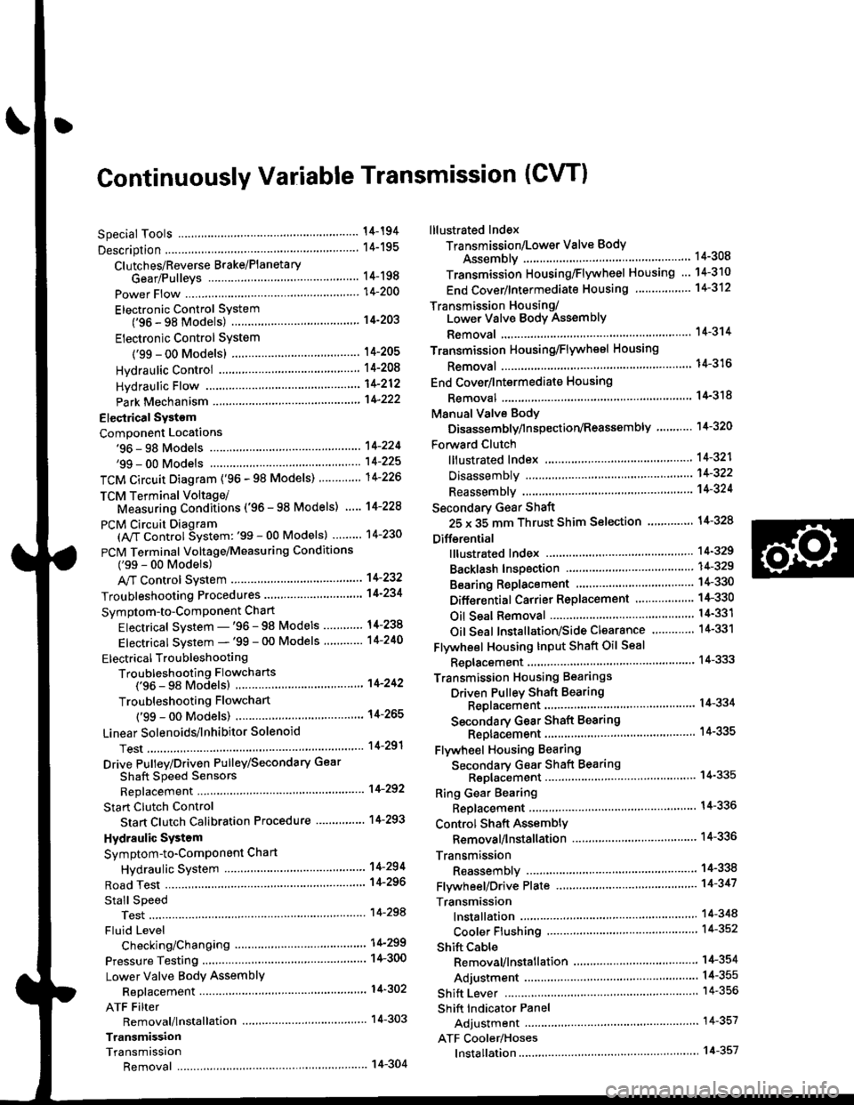
Continuously Variable Transmission (CVTI
Special Tools ................ 14-194
Description .................... 14-195
Clutches/Reverse Brake/Planetary
Gear/Pulleys .......... 14-198
power Flow ..............,..... 14-200
Electronic Control SYstem(,96 - 98 Modets) ......14-203
Electronic Control System
('99 - oo Models) " 14-205
Hydraulic Control '....... 14-208
Hydraulic Flow .'..-.....'... '14-212
Park Mechanism .....-...'.' 14-222
Eleqtrical Systom
Component Locations'96 - 98 Models """"""' 14-224,99 - 00 Modets ............. 14-225
TCM Circuit Diagram ('96 - 98 Models) ............. 14-226
TCM Terminal Voltage/Measuring Condiiions ('96 - 98 Models) '.... 14-228
PcM Circuit Oiaqram{A/T Control System: '99 - 00 Models} ...--.... 14-230
PCM Terminal Voltage/Measuring Conditions('99 - 00 Models)
A/4 Control System .'.'...14-232
Troubleshooting Procedures ... . .... .....',........."' '14-234
Symptom-to-ComPonent Chart
Electrical System - '96 - 98 Models ......'..... '14-234
Electrical System -'99 - 00 Models ..'....-..-. '11-210
Electrical Troubleshooting
Troubleshooting Flowcharts('96 - 98 Models) """'11-242
Troubleshooting Flowchart
('99 - 0O Modets) ...... 14-265
Linear Solenoids/lnhibitor Solenoid
Test ......................... . ...... 14-29f
Drive Pulley/Driven Pulley/Secondary Gear
Shaft Speed Sensors
Replacement .........'...... .14-292
Start Clutch Control
Start Clutch Calibration Procedure ....... ....,. 14-293
Hydraulic SYstem
Symptom-to-ComPonent Chart
Hydraulic System '.'.......14-294
Road Test ............................ 14-296
Stall Speed
Test......................... ...... 14-294
Fluid Level
Checking/Changing ....... 14-299
Pressure Testing ................. 14-300
Lower Valve BodY AssemblY
Replacement ..........,... 14-302
ATF Filter
Removal/lnstallation ..... 14-303
Transmission
Transmission
Removal ........... . 14-304
lllustrated Index
Transmission/Lower Valve BodY
Assembly ................. 14-308
Transmission Housing/Flywheel Housing ... 14-310
End Cover/f ntermediate Housing ..........'.'.... 14-312
Transmission Housing/Lower Valve Body Assembly
Removal ..........'.... .. " 14-314
Transmission Housing/Flywhesl Housing
Removal ................. ........ 1+316
End Cover/lntermediate Housing
14-318Removal .........,...............
Manual Valve Body
Disassembly/lnspection/Reassemblv .'.'.'..... 1 4-320
Forward Clutch
lltustrated Index ........................................ 14-321
Disassemblv .................. 14-322
Reassemblv , ,, . ',','......14-324
Secondary Gear Shaft
25 x 35 mm Thrust Shim Selection ..'.'....-... 14-324
Differential
lllustrated lndex ...,.....................,.,...-.-.-...'... 14-329
Backlash Inspection .-....14-329
Bearing Replacement ......'........'....'... ....'... 14-330
Differential Carrier Replacement ........'........ 14-330
Oil Seal Removal ........... 14-331
Oil Seal Installation/Side Clearance ....... . . 14-331
Flywheel Housing Input Shaft Oil Seal
Replacement .....,.... ...'.'.. 14-333
Transmission Housing Bearings
Driven Pulley Shaft Bearing
Replacenient ...................'. . ...................'.. 14-334
Secondary Gear Shaft Bearing
Reolacbment ...................... . .......... . ........ 14-335
Flywheel Housing Beating
Secondary Gear Shaft BearingReo1acement..................,........................... 14-335
Ring Gear Bearing
Replacement......... ........ 14-336
Control Shaft Assembly
Removal/lnstallation ....................'........... 14-336
Transmission
Reassembly .................. 14-338
Flywheel/Drive Plate .. . ...... . ...... ... . ....-.....'.'...14-341
Transmission
lnstalation ..................... 14-348
Cooler Flushing .'......... 14-352
shift cable
Removal/lnstallation....'........." """ 14-354
Adjustment .......'........ 14-355
Shift Lever ........................,. 14'356
Shift Indicator Panel
Adjustment ................ 14-357
ATF Cooler/Hoses
lnsta llation ......,,...... .... 14-357