7-7 HONDA CIVIC 1996 6.G Workshop Manual
[x] Cancel search | Manufacturer: HONDA, Model Year: 1996, Model line: CIVIC, Model: HONDA CIVIC 1996 6.GPages: 2189, PDF Size: 69.39 MB
Page 198 of 2189

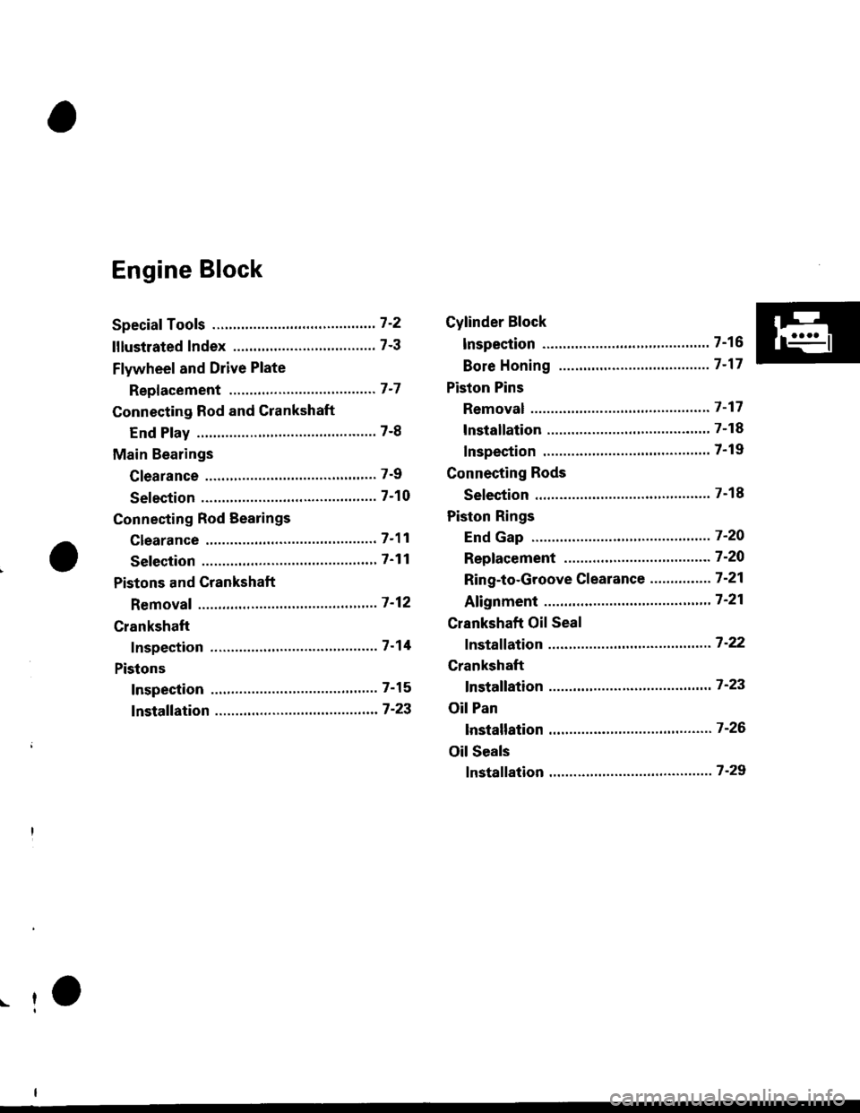
Engine Block
Speciaf Tools ..........." 7-2
lllustlated Index ...................."..'.......... 7-3
Flywheel and Drive Plate
Repf acement """'.' 7-7
Connecting Rod and Crankshaft
End Play ..........."....7-8
Main Bearings
Clearance ............... 7-9
Selection ................7-10
Connecting Rod Bearings
clearance ....'.......... 7-11
Selection ................ 7-11
Pistons and Crankshaft
Removaf ................. 7 -12
Crankshaft
Inspection ."".........7-14
Pistons
Inspection ......"'.....7-15
fnstaffation .............7-23
Cylinder Block
lnspec'tion ..............7-16
Bore Honing ..........7-17
Piston Pins
Removal ...,...........'.7-17
lnstallation .............7-18
Inspection .'............7-19
Connecting Rods
Selection ................7-18
Piston Rings
End Gap ..........".."' 7'2O
Repfacement .........7-2O
Ring-to-Groove Clearance ...........'.'. 7 -21
Afignment .......""'.. 7'21
Crankshaft Oil Seal
fnstaffation .............7-22
Crankshaft
fnstaffation ..-.-..'.".' 7'23
Oil Pan
lnstallation .............7-26
Oil Seals
fnstaffation ....""""' 7-29
r-f
Page 204 of 2189

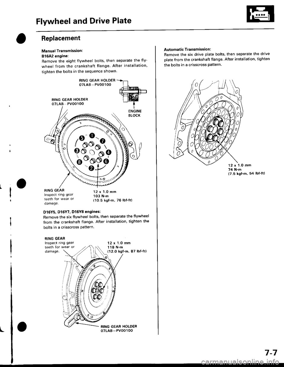
Flywheel and Drive Plate
Replacement
Manual Transmission:
816A2 engine:
Remove the eight flywheel bolts, then separate the fly-
wheel from the crankshaft flange. After installation'
tiohten the bolts in the sequence shown
RING GEAR HOLDER "-i
OTLAB PVOOlOO
D16Y5, D16Y7, D16Y8 engines:
Remove the six flywheel bolts, then separate the flywheel
from the crankshaft flange. After installation, tighten the
bolts in a crisscross Pattern.
RING GEABInspect ring gear
teeth lor wear or
damage.
RING GEARInspect ring gear
teeth lor wear orteetn lor wea( or /danase. ,///.'
12 x 1.0 mm103 N.m(10.5 kgf.m, 76 lbf.tt)
12 x 1.o mm1 18 N,m(12.0 kgI.m, 87 lbf.ftl
L
rurS;u'.\
$..3s'
Automatic Transmission:
Remove the six drive plate bolts, then separate the drive
olate from the crankshaft flange. Atter installation, tighten
the bolts in a crisscross Pattern.
t7.5 kgl.m, 54 lbl'ltl
12 x 1.0 mm74 N.m
7-7
Page 1057 of 2189

l.
t
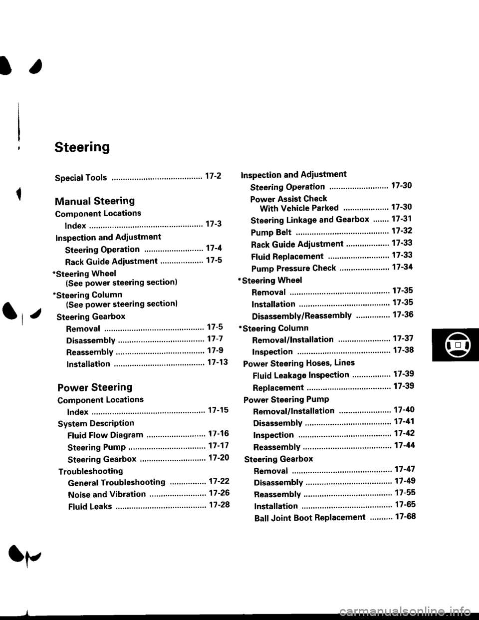
Steering
Speciaf Tools ....."'.....17-2
Manual Steering
Component Locations
lndex ................ ....... 17-3
Inspection and Adiustment
Steering Operation "'......"............... 17-4
Rack Guide Adiustment ................... 17-5
*Steering Wheel
(See power steering section)
*Steering Column
(See power steering sectionl
Steering Gearbox
Removal ................. 17-5
Disassembly ......."" 17-7
ReassemblY ..'......... 17-9
lnstallation ............. 17-13
Power Steering
Component Locations
lndex "......."..... """' 17-15
System DescriPtion
Fluid Flow Diagram .........""............. 17'16
Steering Pump ............'... "........"'...-- 17 -17
Steering Gearbox .".................'...'.'.' 17-20
Troubleshooting
Generaf Troubleshooting ..........--.... 17'22
Noise and Vibration ......................... 17 -26
Ffuid Leaks .............17-28
Inspection and Adiustment
Steering Operation'......."'........'...... 1 7-30
Power Assist Check
With Vehicle Parked .."................ 17-30
Steering Linkage and Gearbox ....." 17-31
Pump Beft ...--.""".. 17-32
Rack Guide Adiustment .'.......'.......'. 17'33
Fluid Replacement .....'.."................. 17-33
Pump Pressure Check .............'....-. " 17 -34
'Steering Wheel
Removal .."'........'... 17-35
lnstallation ............. 17-35
Disassembly/Reassembly ......'.....'.' 17-36
*Steering Column
Removal/lnstallation ....'........... ---.... 17'37
lnspection .............. 17'38
Power Steering Hoses, Lines
Fluid Leakage Inspeetion ............'.... 17-39
Replacement ......".. 17-39
Power Steering PumP
Removal/lnstallation .'.'..'..'............. 17-40
Disassembly ".........17-41
fnspection .......---'." 17'42
Reassembly ..'.........17-44
Steering Gearbox
Removal ....'........."' 17'47
DisassemblY ..........' 17-49
Reassembly '........... 17-55
lnstallation ............. 17-65
Ball Joint Boot Replacement .......'.. 17-68
Ir/
lp
Page 1063 of 2189

)
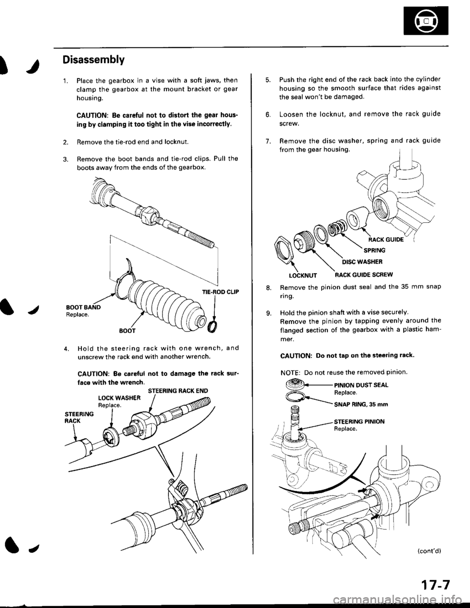
Disassembly
'1.
2.
Place the gearbox in a vise with a soft jaws, then
clamp the gearbox at the mount bracket or gear
housing.
CAUTION: Be carcful not to distort the gear hous-
in9 by clamping it too iight in the vise incorrectly.
Remove the tie-rod end and locknut.
Remove the boot bands and tie-rod clips. Pull the
bogts away from the ends of the gearbox.
/
TIE.ROD CLIP
4. Hold the steering rack with one wrench, and
unscrew the rack end with another wrench.
CAUTION: Be caleful not to damagc the rack sur'
facs with the wrench.
STEERING RACK ENO
l,
17-7
7.
Push the right end of the rack back into the cylinder
housing so the smooth surface that rides against
the seal won't be damaged.
Loosen the locknut, and remove the rack guide
screw.
Remove the disc washer, spring and rack guide
from the gear housing.
RACK GUIOE
SPRING
8.
9.
LOCKNUT RACK GUIDE SCREW
Remove the pinion dust seal and the 35 mm snap
nng.
Hold the pinion shatt with a vise securely
Remove the pinion by tapping evenly around the
flanged section of the gearbox with a plastic ham-
met.
CAUTION: Do not tap on tho steering rack.
NOTE| Do not reuse the removed pinion.
9._
ViF=\_
PINION DUST SEALReplace.
SNAP RING,35 mm
STEERING PINIONFeplace.
DISC WASHER