Clutch trouble shooting HONDA CIVIC 1996 6.G Workshop Manual
[x] Cancel search | Manufacturer: HONDA, Model Year: 1996, Model line: CIVIC, Model: HONDA CIVIC 1996 6.GPages: 2189, PDF Size: 69.39 MB
Page 270 of 2189

!
Fuel and Emrsslons
SoecialToofs .....,...."..,. 11-2
Component Locations
lndex ....................., ......... 11-3
Svstem Description
Vacuum Connections ................,,..,.. ......... 11-12
Electrical Connections ...............,.,.,... ....... 11-29
System Connectors ........,.,.,.......................... 1 1-51
Troubleshooting
Troubleshooting Procedures ................. .. 11-81
Engine Control Module/PowertrainControl Module TerminalAfiangement ....,.,..... 11-88
Diagnostic Trouble Code Chart .................,., 11.97
How to Read Flowcharts .,.......................... . 11-103
PGM-Fl System
System Description ...... 11-10,1
Troubleshooting Flowcharts
Engine Control Module/PowertrainContlol Module ........ 11-107
Manitold Absolute Pressure Sensor .....'. . ... 11-115
fntake Air Temperatuie Sensor ..... . . ., . 11'121
Engine Coolant Temperatuae Sensol ........., 11-128
Throttle Position Sensor ...................,........... 11-132
Primary Heated Orygen Sensor (Sensor 1l ... 11-139
Secondary Heated Oxygen Sensor(Sensor 21.................................................... 1 1-153
Heated Oxygen Sensor Heater ...................,. 11-157
Fuel Supply System ...... 11-164
Random Mislire ......., ..11-166
Misfire Detected in One Cylindsr ................. 11-167
Knock Sensor .,.,............ 11-170
CKP/TDC/CYP Sensor ................................... 11'172
Vehicle Speed Sensor ...........,......,...,.,........... 1t-176
Barometric Pressure Sensor ...............,......... I 1-178
Electrical Load Detector,.,,............................ 1 1-179
CKF Sensor .................... 11-183
ECM/PCM Internal Circuit ............................. I 1-188
A/T Signal {TMA/TMBI .................................. I 1-189
ldle Control System
System Doscriplion ............ 11-190
Troubleshooting Flowcharts
ldle Control System ...... 11-192
ldle Air Control Va1ve .................................... I 1-19i1
Starter Switch Signal .................................... 1 1'202
Air Conditioning Signal ................................. 11'201
Ahernator FR Signal .................................... . 1 1-208
BrakeSwitch Signal ..................................... f 1"210
Power Sleering Prossure Switch Signal ......11-212
A/T Gear Position Signal ............................... 11-216
Clutch Swiich Signal ................................-.... 11-214
ldte Speed Setting . .............11-220
Fuel Supply System
Fuel Lines .,...................,.,.,.,11-221
Fuef Tube/Ouick-Connect Fittings ..........,.,........ 11 -227
System Description ....'.... 11-230
Fuel Pressure .......,.,,........... 11-230
Fuef fniectors ......................11-232
Fu€f Pressure Regulator .....,.......................'...,. 11-231
Fuef Fifter ............................11-235
Fuel Pump .............'.......'.... 11-236
PGM-FI Main Relay .............11'237
Fuel Tank ................ ....,...'.'.' 11'211
Intake Air System
System Description ....-.-.....11-243
Air Cfeaner ...........,......."". .11-211
Throttle Cable .....................11-211
Throttfe Body ........ ..'... . . .,.11-211
Fuel Iniestion Air Control System ,.,.,....-........... 11-250
Emission Control System
System Description .-..........11-252
Taifpip€ Emission ...............11-252
Three Way Catafytic Convert€r ............,.,,.,.,.,.... 11 -252
Exhaust Gas Racirculaiion System ...,.,,,,.,.,.,.,,. 11'254
Positive Crankcas€ Ventilation System .... . . .. 11-266
Evaoorative Emission Controls ..................,,..,.,. 11 -267
Page 276 of 2189
I
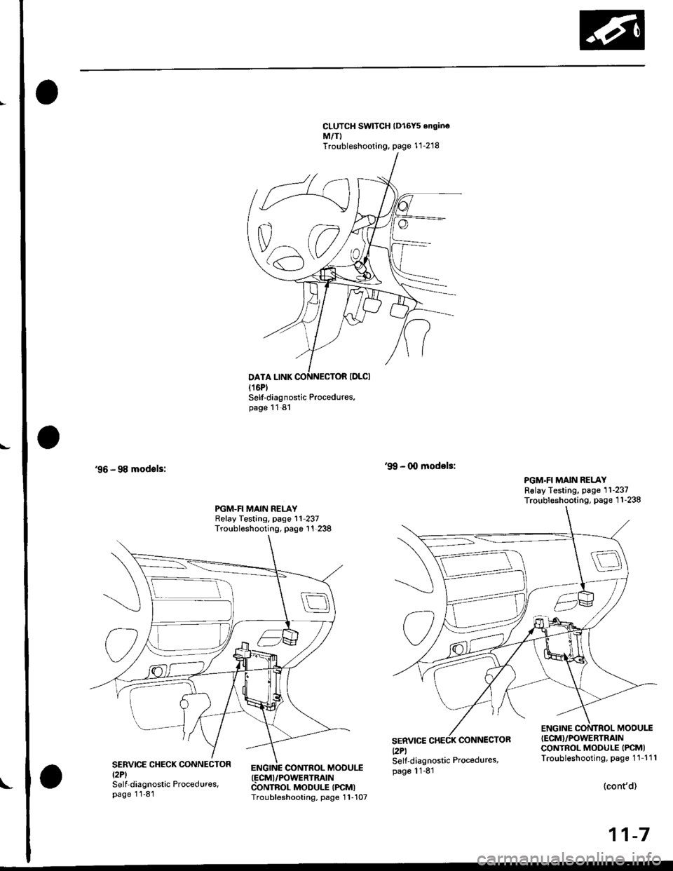
CLUTCH SWITCH lDl6Y5 onginoM,/TITroubleshooting, page 1 1-218
'96 - 98 modsls:
Sell-diagnostic Procedures.page 11 81
ENGINC CONTROL MOOUI.T(FCMI/POWERTRATN
CONTROL MODULE IPCMITroubleshooting, page 1 1-107
'9!, - 0o modol3:
PGM.FI MAIN RELAYRslay Testing, page 11-237Troubleshooting, page 1 1-238PGM.FI MAIN RELAYRelay Testing, page l1 237Troubleshooting, pago 1'! 238
SERVICEl2Pl
CONNECTOR
ENGINE CONTROL MODU1T(ECM}/POWERTRAIN
CONTROL MODULE IPCMITroubleshooting, page 11 111SERVICE CHECK CONNECTORtzPlSelf-diagnostic Procedures,page 11-81
Self-diagnostic Procedures,page 11-81
{cont'd)
11-7
Page 357 of 2189
Troubleshooting
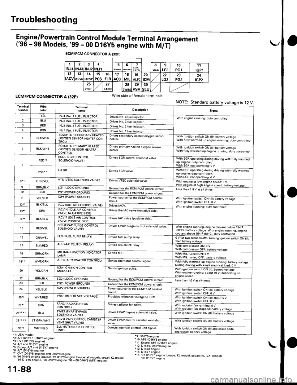
E n gine/P_o,weft ra in Control Module Term inal Arra n gement('96 - 98 Models, '99 - 00 Dl6yS engine with M/T)
-
ECM/PCM CONNECTOR A I32PI
1INJ62INJ3INJ21
INJl567I
LG110PGll1
IGPl12
ACV
131115
PCS
16
FLR17acc18MIL19ALTC20
tcM22PG221IGP2272A25
VSV30
SLU
ECM/PCM CONNECTOR A (32P)
'2: A./T (D16Y7, 016Y8 engine)13: CvT (D16Y5 enoin€)',4: A/T and D16y7 engine*5: Except A/T and D16Y7 €nsine'6r A/T (D16Y8 ensine)'7 Cw 1D16Y5 eng,nel and D16y8 ensrne'"'3:Bi..I?'Jt;".'e'.!ti.?i?l'""."T8"_";btfr
"fl
1-88
Wire side of female terminals
NOTE:Standard battery voltage12ts
'10i i,4/T (D16V5 engine)r11 Ex.ept M/l (D16V5 enqinelr12: 016Y5, D16YB enqine
r15:'97 016Y7 engine lcoupe: KL modet, sedan: KL (LXl modet),'98 D16Y7 engine
1
1
Sign.l
YELlNJ4 (No.4 FUEL INJECIOB)D ves No 4 ruel injector.Wilh engine runninq: ddly coniroted2BLUlNJ3 lNo. 3 FUEL TNJECTOBJDrives No. 3 lue Inteclor.38EDINJ2 (NO, 2 FUEI INJECTON)Drives No. 2 iuel njector.88NlNJl (No. 1 FUEL INJECTOB)Dives No. 1 ruelinjector.
5SO2SIITC (SECONDAFY HEATEDOXYGEN SENSOF HEATEF CONTFOL)
Orives secondary heated oxyqen sensorWith ignilion switch ON (lll: batery vo lageWith f!llywarmed up engine runninq:dLtv controled
6BLXAVHTPO2SHTC (PRIMAFY HEATEOOXYGEN SENSOR HEATERCONTROL)
Drives prihary healed oxygen sensorWith ignition switch ON ltt):baneryvottasewlhrdllywdrmedupcngne,Lnnrrq dury,orl.otred
FED{ESOL (EGF CONTRO!SOIENOIO VALVE)Drives EGF conlrolsoleno d vatve.Wilh EGR operating during drving wiih fu|y warmedup engrne: duty controttedWilh EGF nol opefating:O VE.EGRWith EGF operating du.ing driv og wilh iuty warmedup en9ine: dutycont.olted.With EGR not ooeralino; o V8*r/GFN/YELWS (VTEC SOLENOTD VALVE)Drives VTEC solenoid va veWilh eng ne at ow engine speed:O VWirh engine at h gh enqine speedr banery vohaae9BflN/BLKLG1 (LOGIC GROUND)Gro!nd lorthe €CM/PCM conlrotc rcuit.Lesslhan 1.0 V at a ttimest0ALKPG1 IPOWEF GFOUND)Ground ior rhe ECM/PCM power.tcuf.11YEVBLKIGPT iPOWEF SOUFCE)Power source forthe Ec[,l/PcM conlroWilh ignition swirch ON (tt): battery voltageWith gntron switch OFF: 0 VBLVBLUIACV (IDLE AIN CONTROL VALVE)Wilh engine r!nn ng: dlty contro ed13,.o8NIACV N lIDLE AI8 CONTFOLVALVE NEGATIVE SIOE)Drivesthe IAC valve {negalive side).
BLVBLUIACV P (IDLE AI8 CQNTROLVALVE POSITIVE SIDE)Orives IAC vaive (posilive side).
FEO/YELPCS (EVAP PURGE CONTFOTSOIENOIOVALVE)Drives EVAP pu.ge controtsolenoid vatve.Wilh engioe running, engin€ cootani betow 154,F'68'Cr bancry vohaSe w'ln ens nc runn,.o. eng,rc
GRN/YELFL8 (FUEL PU[4P FELAY)Orives fuelpump relay.0 V {or two secor os ahe' tJ n ng 'onir or \wnch ON ,,,,,
I7BLI(REOACC (A,/C CLUTCH RELAY)Drives A/C clutch relay.Wirh compressor ONr0 VWilh compressof OFF:banery votrage18GFN/ONNMIL (I\,lALFUNCTION INDICATOFWith MIL lLrned ON: 0 VWith illl turned OFF: banery volaqe19',AITC {AITERNAIOR CONIROL)se.ds ahernator controt signat.Wirh fully warmed.up engine ru.ntng: battery votlas€During drivins wnh smatl eteclricat toad: O V
20YEVGRNICM (IGNI'TION CONTROLMOOU!E)with ignltlon swilch ON (tl):b6n€ry vohageWilh ensine runnins: aboul t0 V (depending on
22BRN/BLKLG2 (LOGIC GAOUND)Ground for the ECM,/PCM conrrot ci'cu LLess than 1.0 V at a tt mes23BLKPG2 iPOWEA GROUND)Gro!nd lor the ECM/PCM power circuir.24YEUBLKlGP2 (POW€R SOUSCE)Power sou.ce lor the ECM/PCl, conrrolWnh ignilion swilch ON {it):battery vohageWilh ignilion switch OFF:0 V25*6WHT/FEDVSEF IREFEfl ENCE VOLTAGE)Provrdes reference voIaOe to TCM.With ignition switch ON (tt):abour 5 VWth gnition swltch OFF: O V21'1GFNFANC {RAOIATOR FANCONTFOL)Drives radialof fan ielay.With radialor fan f!nn nqr O VWilh radiato.tan stopped: batteryBL!2WBS (EVAP BYPASSSOLENOIO VALVE]Orives EVAP bypass sotenotd va !e.With ignirion swrrch ON (tt):barery vo rase
LT GRNA/VHTVSV (EVAP CONTFOTCANISTEFVENT SHUT VAIVE)Drives EVAP conlfot canisrer venl shulwnh ignirion sw'tch ON lr|l barery volaqe
WHT/NEDSLU (INTEFLOCK CONTFOLUNIT)Detects intenock conlrotLn t signalWhh ignition switch ON (tt)and brake pedadepf essed: battery vollage
Page 359 of 2189
Troubleshooting
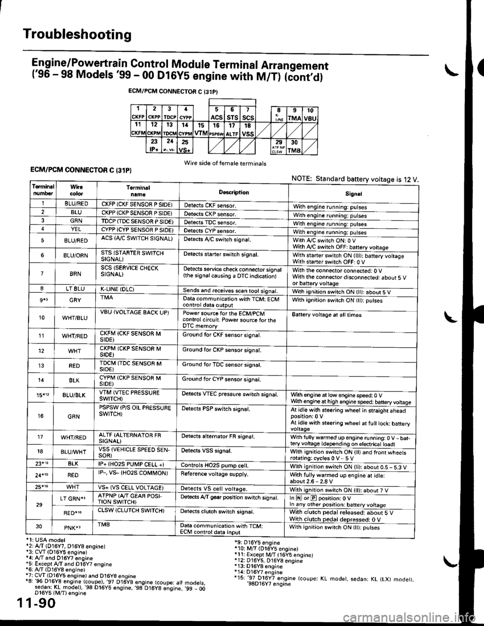
Engine/P_o_wgrtrain Control Module Terminal Arrangement('96 - 98 Models '99 - 00 Dt6y5 engine with M/T) tc'oniOi
ECM/PCM CONNECTOR C {31PI
1
CKFP
2
CXPPTDCPa
ACS
5
sTs
7
scsII
rMA
10
v8u121314t51517
ALTF
TE
vss23lP+
21252930
TMA
Wire side of female terminalsECM/PCM CONNECTOR C (31PI
NOTE: Standard baftery voltage is 12 V
'1: USA modelr2rA,.T (D16Y7, O16Y8 ensane)*3: CVT (O16Y5 engine)*4: Ay'T and O16Y7 engine'5: Excepl A./T snd Dl6Y7 engine16: Ay'T (D16Y8 ensine){7: CVT (Dl6Y5 eosine) and O16Y8 enoine"8: 96 Dl6Y8 engine (coupe),'97 D16y8 engine (coupe: atl:ed-9I t!!rnodelr,'98 D16y5 ensine,,98 D16y8 e;sine.D16Y5 lM/T) ensine
1-90
19: D16Y5 engine'10: M/T (Dl6Y5 engine)*11r Except M/T 116Y5 engine)*12: D16Y5, D16Y8 engine*13: Dl6Y8 enqine*14: O16Y7 enginei15: '-97 O16Y7 engjne (coupe: KL modet, sedan: KL (LX) modet),'98D16Y7 enqine'99 - 00
1
To.min!lnumberWiracoloaTorminalnameDo6criptlonSignal
1BLU/REDCKFP (CKF SENSOR P SIDE)Detects CKF sensor.With engine running: pulses2BLUCKPP (CKP SENSOF PSIDE)Detects CKP sensor.With engine running: pulses3GRNTDCP {TDC SENSOR PSIDE}Detects TDC sensor,With engine running: putses4YELCYPP (CYP SENSOR P SIDE)Detects CYP sensor.With engine running: pulses
5BLU/FEDACS {Tr'C SWITCH SIGNAL)Detects ,ay'C sw;tch signat.With Iy'C switch ONr 0 VWith Ay'C switch OFF: batrery vottage
6BLU/ORNSTS (STARTER SWITCHSIGNAL)Detects staner swilch signal,With staner switch ON ltlt): batery vohageWith staner switch OFF: 0 V
8RNSCS (SERVICE CHECKSIGNAL)Detects service check connector signal{the signalcausing a OTC indicationlWith the connector connected: O Vwith the connector disconnected: about 5 vor battery voltageLT 8LUK,LINE (DLC)Sends and receives scan iool signal,Wirh ignition switch ON { ): about 5 V
9+3GRYDat6 communication with TCM: ECMcontrol ctat6 outputWith ignition switch ON (tt):putses
10WHT/BLUVBU (VOLTAGE BACK UP)Power source forthe ECM/PCMcontrol circuit. Power sourc€ lortheDTC memory
Battery voltage at all times
11WHT/REDCKFM {CKF SENSOR MSIDE)Ground tor CKF sensor signal.
12CKPM (CKP SENSOR MSIDE)Ground for CKP sensor s;gnat.
REDTDCI\4 (TDC SENSOR MSIDE)Ground for TDC sensor signal.
14BLKCYPM (CKP SENSOB MSIDE}Groond for CYP sensor signal.
15."BLU/BLKVTM (VTEC PRESSUREswtTcH)Oetscts VTEC pressure switch signal.Wrth engine at low enginespeed:0 VWth engineathigh engine speed: tatteryvoltase
16GRN
PSPSW (P/S OIL PRESSUREswtTcH)Detects PSP switch signal.At idle with steering wheel in straight aheadposition:0 VAt idle with stsering wheet at fult tock batteryvoltage'17WHT/REDALTF (ALTERNATOR FRSIGNAL)Detects ahernator FR signal.With fullyw6rmed up engine running:0 V- bat-teryvohage (depending on electricat toad)18BLUI/VHTVSS {VEHICLE SPEED SEN-SOR}Oetects VSS signal.Whh ignitjon switch ON {tt) and front wheetsrotating: cycles 0 V- 5 V23+14BLKlP+ {HO2S PUtr4P CELL +}Controls HO2S pump ce .With ignition switch ON (ll): abour 0.5 - 5.3 V
24.10REDrP-, vs- {Ho2s coMt oN)Reference voltage supply.With fullywarmed up engine et idle:about2.6-2.8 V25*roVS+ (VS CELL VOLTAGE)Detects VS cell voltage.With ignition switch ON t): abour 7 V
29LT GRN*'ATPNP (Ar'T GEAR POSI,TroN swrTcH)Deteds Ay'T g6srposhion switch signat.In E orE position: O Vln any other position: battery vottage
RED{roCLSW (CLUTCH SWITCH}Detects clutch switch signal,Wilh clutch pedal released: about 5 VWith clutch pedal deDressed: O V30PNK4TMBData communication with TCM:ECM controldata inputWith ignit;on switch ON (lt):putses
Page 361 of 2189
Troubleshooting
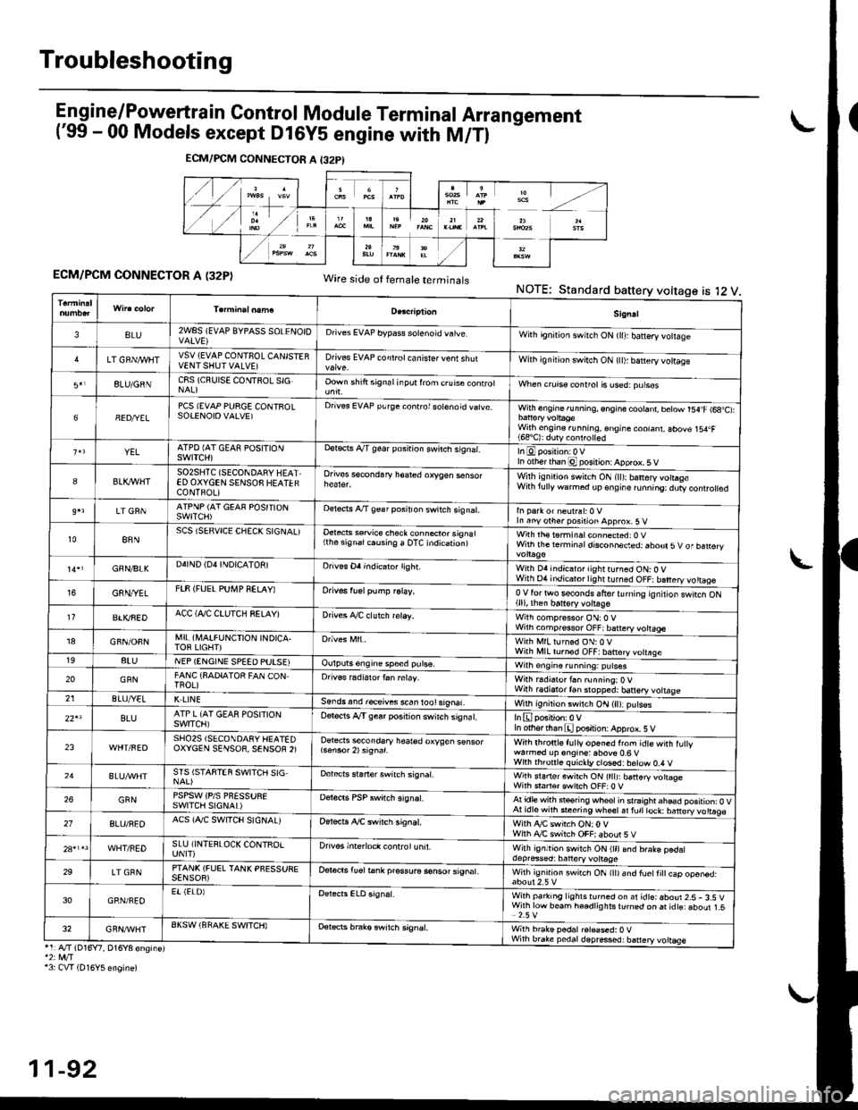
Engine/P_o,wertrain Control Module Terminal Arrangement('99 - 00 Models except Dl6Y5 engine with M/Tl
ECM/PCM CONNECTOR A (32P)Wire side ot temale terminalsNOTE:Standard battery voltage is l2 V
ECM/PCM CONNECTOR A I32PI
Sign!l
3BLU2WSS (EVAP 8YPAsS SOLENOIDDrives EVAP bypass solenoid vatve,With gn'tion swnch ON (lll banery votlage
LT GRN/I/VIITVSV {EVAP CONTNOL CANISTERVENTSHUTVALVE]Drives EVAP controt ca n isrer v€nt shutWilh ignilion switch ON {tl): b€ttery vottage
8LU/GNNC8S (CRUISE CONTSOL SIGOown shift signal inpot lrom c.uise conrrolWhen crurss control is used:purses
68ED/YELPCS {EVAP PURGE CONTROLSOTENOIOVALVE)Drives EVAP purge conrrol sotenoid vatve.With engine running, engine cootant, betow r54.F (6a,C):
With engine.unning, €ngine coolant, abov€ 154.F(68'C): duty conlrolled
YELATPD {AT GEAR POSITIONSWITCH)ootects A/T gear posnion swilch s,gnar.In otherthan @ posilion: Apprcx. 5 V
8BLK,IflHTSO2SHTC (SECONDARY HEATED OXYGEN SENSOS HEATEFCONTFOL)
Drives sscondary h€ared oxygen senso.Wilh isn,rion swirch ON (ll):banery votraseWith lully warm6d dp€ngire runn'ng:dury controled
LT GRNATPNP (AT GEAF POSITIONSWITCH)oereds A/T 9€a r position switch signat.In Parr or neulrsl:0 VIn anyother position approx.5 v
t088NSCS (SERVICE CHECK SIGNAL)Oetects ssruice check connecror signal(the signalcausing a OTC indication)with rh€ t6rminal connected: 0 vWith the rerm ina I disconneded: abour 5 V of ban€ry
GNN/BIKD4IND (D4INDICATON]Drives Oa indicaio. lighr.With D4 indicator lightturned ON: O VWith D4 indicator lightturned OFF: battery vo ttageG8N/YETFTF (FUEL PUI\,4P SELAY)Orivos tuel pump relay,0V for two s€conds lfrer turnrng rgnilior swtcn ON(ll), then batt€ry voltage11BTI(REDACC (Al/C CTUTCH SELAY)Drives A./C clutch reray.With compressor ON:O VWilh comp.ssor OFF; battery vottage18GFN/OFNMI! (A,IAIFUNCTION INDICA.TOF LIGHT)With MlLturned ON:0 VWith l\,llL tornod OFF|batrery votrsge198tuNEP (ENGINE SPEED PUTSEIOulputs6ngine speed pulse,Wilh engin6.unning: putses
20GFNFANC {SADIATOR FAN CONTnoL)Orives radiarortan relay.Wirh r.distor t6n running:OVWith radiatortan stopped: banery vottage21ELUA/ELK LINESends and r€ceives s.an lool signal.With ignition switch ON (ll):p!ts€s
22'lBLUATP L {AT GEAS POSITIONswtTcH)Oelocis A"/T gear posirion switch siSnat.In othfflhan E position: Apprcx. 5 V
23SHO25 (SECONOARY HEATEDOXYCEN SENSOR, SENSOF 2)Detects secondsry hoar€d oxygen sensorWith lhronle f! lly or'6ned from idte with fu ywarmod up engine: above 0.6 vWiih th.onl6 quickb, closd:below 0,4 V24STS ISTAFTEN SWITCH SIGDebcrs staner switch signat.Wirh srarterswitch ON (tttJ: batteryvottogeWith sraftsr cwirch OFF:0 V26GFNPSPSW iPlS PNESSURESWITCII SIGNAL)Derecrs PSP switch signat.Atidle with steoring wheolin srraightahead position: O VAt idl6with steering wheetal fult lock: barery vo ttags27BLU/REOACS (AJC SWITCH SIGNALJOer*ts ,ay'C swirch signat.Wiih ty'C switch ON;0VWilh Ay'C switch OFF|aboor 5VWHT/REDSLU iINTERLOCK CONTROIUNIT)Drivos interloct control unit.With ignltion switch ON (ll)and brake pedaldepresed: batlory volrage29LT GRNPTANK (FUEL TANK PFESSUEESENSOR)Oer6ds lu€l tank pr€ssura sonsor signat.Wilh ig.rrrd swirch ON rttr and fuetti
cap ooen6d.
30GRN/FEOEr (ELOIWith parking lighlsrurned on ar idteiaboui 2.5- 3.S VWirh low beam he€dlig hts turnqd on ai idts: aboul 1.52.5 V32GRN/'WHTAKSW (BFAKE SWITCH)Detets brak€ swrtch signEt,With brake pedal r6l€ased:0 VWhh brake pedaldepres*d: battery voltEse'1:A./T (D16Y7, D16Y8 engine)*2: rvt/T13: CVT (D16Y5 engine)
11-92
Page 374 of 2189
3.
5.
6.
1.
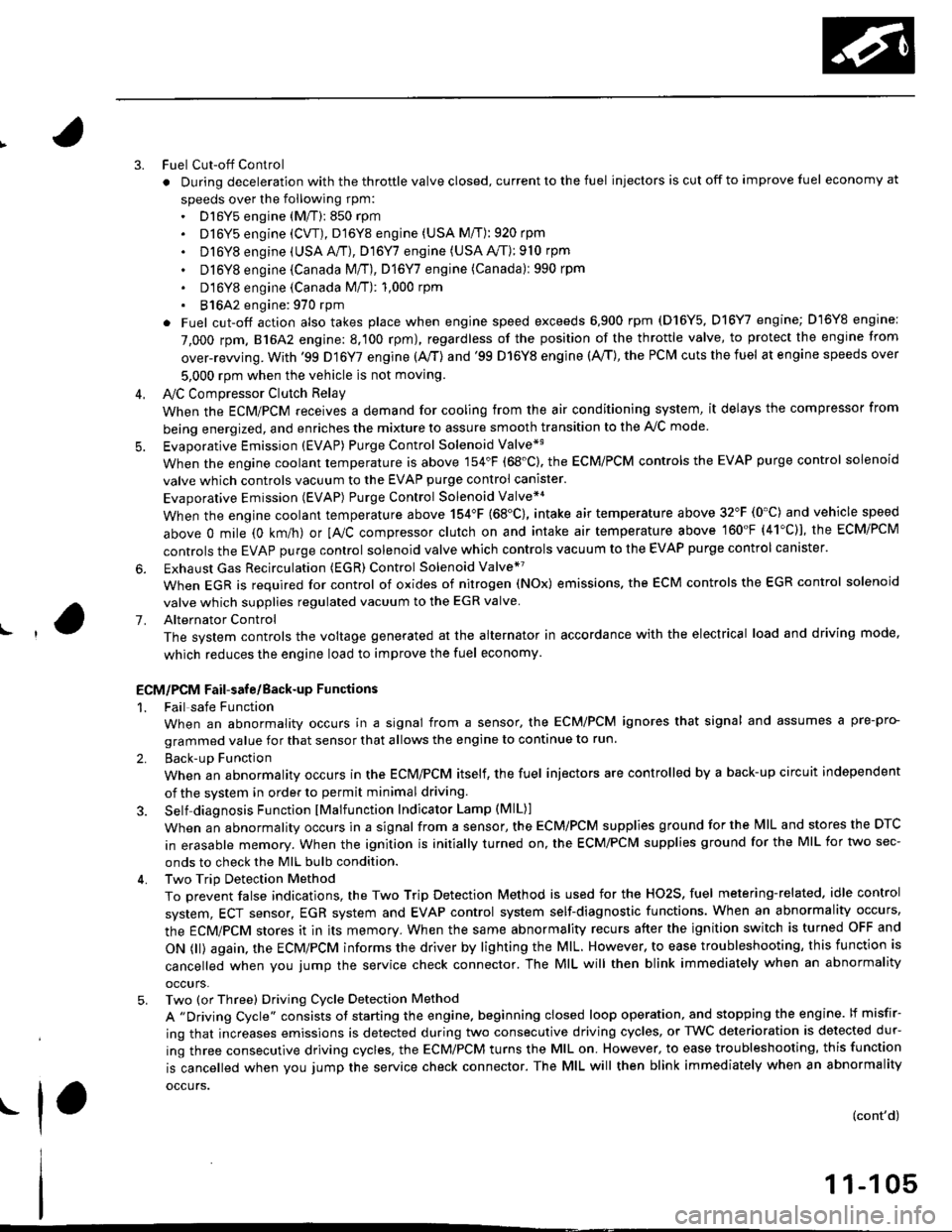
Fuel Cut-off Control
. During deceleration with the throttle valve closed, current to the fuel injectors is cut off to improve fuel economy at
speeds over the following rpm:. D16Y5 engine (M/T):850 rpm. D]6Y5 engine (CVT), D'16Y8 engine (USA M/T): 920 rpm
. Dl6Y8 engine (USA A,/I), D16Y7 engine (USA A,/T);910 rpm
. D16Y8 engine (Canada M/T), D16Y7 engine (canada): 990 rpm
' D16Y8 engine (Canada M/T): 1,000 rpm
. 816A2 engine: 970 rpm
. Fuel cut-off action also takes place when engine speed exceeds 6,900 rpm (D16Y5, D16Y7 engine; D'16Y8 engine:
7,000 rpm. 816A2 engine: 8.100 rpm), regardless of the position of the throttle valve, to protect the engine from
over-rewing. With '99 Dl6Y7 engine (A,/T) and '99 D16Y8 engine (A./T), the PCM cuts the fuel at engine speeds over
5,000 rpm when the vehicle is not moving.
IVC Compressor Clutch Relay
When the ECM/PCM receives a demand for cooling from the air conditioning system, it delays the compressor from
being energized, and enriches the mixture to assure smooth transition to the A,/C mode
Evaporative Emission (EVAP) Purge Control Solenoid Valve*'
When the engine coolant temperature is above 154'F (68'C). the ECM/PCM controls the EVAP purge control solenoid
valve which controls vacuum to the EVAP purge control canister.
Evaporative Emission (EVAP) Purge Control Solenoid Valve*a
When the engine coolant temperature above 154"F (68"C), intake air temperature above 32"F (0'C) and vehicle speed
above 0 mile (0 km/h) or [Ay'C compressor clutch on and intake air temperature above 160"F (41'C)], the ECM/PCM
controls the EVAP purge control solenoid valve which controls vacuum to the EVAP purge control canister.
Exhaust Gas Recirculation (EGR) Control Solenoid Valve*?
When EGR is required for control of oxides of nitrogen (NOx) emissions. the ECM controls the EGR control solenoid
valve which supplies regulated vacuum to the EGR valve
Alternator Control
The system controls the voltage generated at the alternator in accordance with the electrical load and driving mode,
which reduces the engine load to improve the fuel economy.
ECM/PCM Fail-safe/Back-up Functions
1. Fail safe Function
When an abnormality occurs in a signal from a sensor, the ECM/PCM ignores that signal and assumes a pre-pro-
grammed value for that sensor that allows the engine to continue to run.
2. Back-uD Function
When an abnormality occurs in the ECM/PCM itself, the fuel injectors are controlled by a back-up circuit independent
of the system in order to permit minimal driving.
3. Self diagnosis Function lMalfunction Indicator Lamp (MlL)l
When an abnormality occurs in a signal from a sensor, the ECM/PCM supplies ground for the lvllL and stores the DTC
in erasable memory. When the ignition is initially turned on, the ECM/PCM supplies ground for the MIL for two sec-
onds to check the MIL bulb condition.
4. Two Trip Detection Method
To prevent false indications, the Two Trip Detection Method is used for the HO2S, fuel metering-related. idle control
system, ECT sensor, EGR system and EVAP control system self-diagnostic functions. When an abnormality occurs,
the ECM/PCM stores it in its memory. When the same abnormality recurs after the ignition switch is turned OFF and
ON 0l) again, the ECM/PCM informs the driver by lighting the MlL. However, to ease troubleshooting, this function is
cancelled when you jump the service check connector. The MIL will then blink immediately when an abnormality
occurs,
5. Two (or Three) Driving Cycle Detection Method
A "Driving Cycle" consists ot starting the engine. beginning closed loop operation, and stopping the engine. lf misfir-
ing that increases emissions is detected during two consecutive driving cycles, or TWC deterioration is detected dur-
ing three consecutive driving cycles, the ECM/PCM turns the MIL on. However, to ease troubleshooting, this function
is cancelled when you jump the service check connector. The MIL will then blink immediately when an abnormality
occurs.
(cont'd)
1 1-1 05
.1.
Page 581 of 2189
\
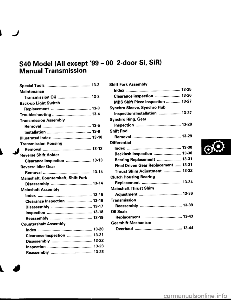
S40 Model (All except'99 - 00 2-door Si' SiR)
Manual Transmission
Special Tools ..'.......... 13-2
Maintenance
Transmission Oil .............................. 13-3
Back-up Light Switch
Replacement ......... 13-3
Troubleshooting '....... 13-4
Transmission AssemblY
Removal ................. 13-5
lnstallation ............. 13-8
lllustrated Index ...............'........."........ 13-10
Transmission Housing
I Removaf .."""""""' 13-12
J R"rr"r"" Shift Holder
Clearance lnspection ....................... 13-13
Reverse ldler Gear
Removal ....'.........." 13-14
Mainshaft, Countershaft, Shift Fork
Disassembly ......'... 13-14
Mainshaft AcsemblY
Index ............... ....... 13-15
Clearance Inspection ..'.................... 13-16
Disassembly .......... 13-17
Inspection ....'......... 13-18
Reassembly ........... 13-19
Countershaft AssemblY
lndex ................ ...... 13-20
Clearance lnspection ."..........'......." 13-21
Disassembly ..."""' 13-22
Inspection .............. 13-23
Reassembly ..'.""... 13-23
Shift Fork AssemblY
lndex ............... ."'... 13-25
Clearance lnspection ."......."........'.. 13'26
MBS Shift Piece Inspection ....-.....'.. 13'27
Synchro Sleeve, Synchro Hub
f nspection/lnstallation .......'...... ".... 13'27
Synchro Ring, Gear
Inspection '....'..".... 13'28
Shift Rod
Removal .'......".""" 13'29
Differential
lndex ......."'...... .'."' 13-30
Backlash Inspection ..........."......."... 13-30
Bearing Beplacement'.............'.".... 13'31
Final Driven Gear Replacement '..... 13-31
Thrust Shim Adiustment ..."........... 13-32
Clutch Housing Bearing
Replacement .......'. 13-34
Mainshaft Thrust Shim
Adiustment '....'..".. 13-36
Transmission
Reassembly ........... 13-39
Oil Seals
Replacement ......... 13-43
Gearshift Mechanism
Overhaul ................ 13-44
\
Page 584 of 2189
Troubleshooting
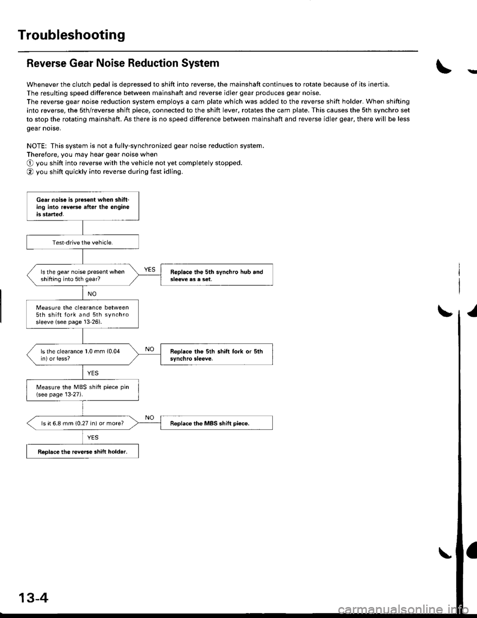
Reverse Gear Noise Reduction System
Whenever the clutch pedal is depressed to shift into reverse, the mainshaft continues to rotate because of its inertia.
The resulting speed difference between mainshaft and reverse idler gear produces gear noise.
The reverse gear noise reduction system employs a cam plate which was added to the reverse shift holder. When shifting
into reverse, the sth/reverse shjft piece, connected to the shift lever, rotates the cam plate. This causes the sth synchro set
to stop the rotating mainshaft. As there is no speed difference between mainshaft and reverse idler gear, there will be less
gear norse.
NOTE: This system is not a fully-synchronized gear noise reduction system.
Therefore, you may hear gear noise when
O you shift into reverse with the vehicle not yet completely stopped.
@ you shift quickly into reverse during fast idling.
-
Gear noise is oresent when shift-ing into reverce after the engineis started.
Test-drive the vehicle.
ls the gear noise present whenshifting into 5th gear?Beplace the 5th synchro hub and3leeve e3 a set,
Measure the clearance between5th shift fork and 5th synchrosleeve {see page 13'26).
ls the clearance 1.0 mm (0.04
in) or less?
Measure the MBS shift piece pin(see page 13-27).
ls ( 6.8 mm (0.27 in) or more?Replace the MBS shift piece.
ReDlace the reve6e ahift hold.r.
13-4
Page 679 of 2189

Automatic Transmission
Special Tools ......... .....'."".'-.-.' 14'2
Description .,....................-...... 14-3
power Flow ......,................. 14"6
Elestronic Control System .... . ................'..'.'.. 14-13
Hvdraulic Control .....'......" 1'l-19
Hydraulic F|ow...... .'.'.".'....11-21
Lock-up System '............ ... t/t'33
Electrical System
Component Locations....,.............'......'.............'.,. 14'39
PCM Circuit Diagram
lA/T Control Syst€m: '96 - 98 Models) .........'.. 1/t-40
PCM Tarminal Volt8ge/Measuring Condhions
{'96 - 98 ModeblA/T Control System ............
PCM Circuit Disgram(A/T Conlrol System: '99 - 00 Modsls) '..........' 14-44
PCM Terminal Voltage/Measuring Conditions('99 - 00 Models)A/T Control System ...
Troubleshooting Proceduros ....
Symptom-to-ComPonent Chari
Efectricaf SFiem - '96 - 98 Models '..-.-..."'.'..11-52
Eloqtrical System -'99 - 00 Modols ... .........". 1+54
EleclricatTroubl$hooting ('96 - 98 Models)
Valve Body
Repair .................... ........'.... 14-139
Valve
Assembly
ATF Pump
1,1-1i10
Inspection ...........'.......... 14-141
Main Valvs Body
Disass€mbf y/lnspoction/R.sssembly .'.'.'.'.. -. -. 1 1-1 12
Secondsry Valve BodY
Disa$embfy/lnspoction/Rsassembly ......'.'.'.'. 11-111
Regulator Valve Body
Disa$embly/lnspoction/Rea3sembly ..........'... 14-1{5
Servo Body
Disassombly/lnsp€ction/Reassembly .".'........ 14-146
Lock-up Valv6 Body
Dis$s.mbf y/ln3poction/Rea$embly .'.. -. -..'.'.' 1 1-1 17
Mainsh!ft
Dkassembly/lnep€ction Reassembly ..'...'........ 14'148
Inspoction .............'..........'. l it-149
Countsrshaft
Disa$embly/lnspeqtion/Rea3sembly .......'...'.. 1a-l51
Dba$ombly/Re$s.mblY11-152
til-46
I rl-48
Troubleshooting Flowcharts
Electrical Troubleshooting ('9!t - 00 Models)
Troublsshooting Flowchart3
Lock-up Control Solenoid vslvo A/B AssemblY
RePlacoment
Shift Cont.ol Solenoid Valve A/B A3sembly
Inspestion
Ona-way Clutch
Disassembh/lrupoction/Rca$embly .. "'........ l4-155
Clutch
lllustlttcd Ind.x {A48A, B4RA Transmlssion) ..' 14-156
tustr.tod Index (MrnA Transmi$ionl ............ til-158
...................... 14-153
L
14-56
1+81'
14-105
1+105
Replacoment ......
Mainshaft/Countorshaft Spo€d Sonsors
Replacemsnt ......'."'........... lit'108
Hydraulic System
Symptom-to-Componeni Chart
Hydraulic Sydemr+109
t4-113
1+116
11-117
Rea$emblY
14-106 Difforrr ial
llhdraied Index........ t4-156
B.ckhrh ln3poction. 14-167
Boaring Roplacemont..-..........11-167
..... 14-108 Diftrrsniial Carrior Repl8cemeni .'.-.............'...' lil-168
Oil Sall Romovalt4-t 59
Oil Soal ln3tallstion/Sidc Clearance'......'.....'... 1'l'169
Torqua Convertcr Housing Boarings
Mlin3haft Besring/Oil Scal Roplac.ment ."..'.. lil-172
Counio6hatt Betring R.plscem.nt ..'...... ....... 14-173
Test.....,......14-106
14-107
14-160
11-162
11-171
11-175
Replacement
Test .....,.,..........
Road Te3t
Linear Solenoid AsssmblY
Stall Speed
lllustrated Indax
Transmission/End Cover'. ....
Transmission Hou3ing,.............'.'......'....""..-.-.. 11-128
Torque Conve.ter Housing/Valvo Body ........... 14-130
End Cover
14-itB Park Stop
1+119 In3pection/Adiustmsnt...'......'.'............'...."""'14-175
Transmbgion
Reassombly
11-122 Torquo Convertet/Drivr Plsie ............'.'............'.. . l4-182
Transmission
11.726 Inrtallation
Tranlmission Housing Boarings
Msinsh.ft /CounteEhaft Bearings
B!pltcomgnt
Rcvo.3s ldlor Gear
lnrtallation
Cooler Flushing ..
Shift Cabls
Test
Fluid Level
Checkin9 .........."..'.'.....
Changing
Pressure Testing
Transmission
Transmission
Rgmoval ..
lil-176
.'..........'.'.'..... 1'l-183
.... lil-187
11-132Adiustmont
RemovaUlnttallation1,1-190
lit-191Transmisgion Housing
Removal ... '.'...... ......'..... 14-l3il
Tolque Convgrter Housing/valvs Body
Rsmoval .........,...... ............. 14-136
Valve CaDs
Description .......'................. t 4'138
Shift lndicator Panel
Adiu3tmant ..'.................. 14-192
ATF Coolor Hoses
Connection ..,............,.,....... l'l-192
Shift Lever .,........
Page 753 of 2189
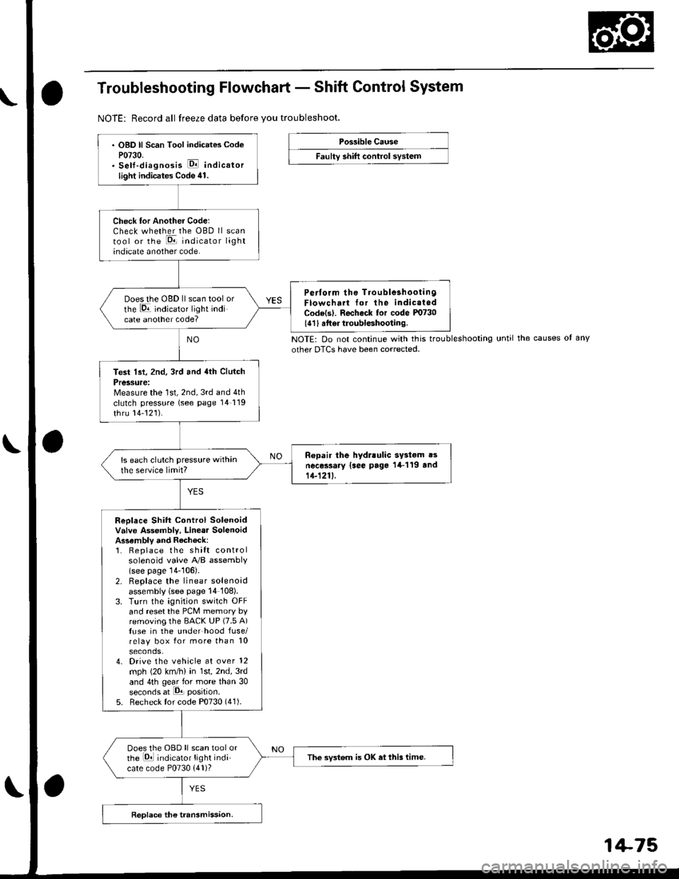
Troubleshooting Flowchart - Shift Control System
NOTE: Record all freeze data before vou troubleshoot.
Possible Cause
Faulty shift control system
. OBD ll Scan Tool indicates CodeP0730.. Sell-diagnosis E indicator
light indicates Code ill.
Check tor Another CoderCheck whether the OBD ll scantool or the E, indicator lightindicate another code.
Perlorm ths TroubleshoolingFlowch.rt for the indic.t.dCode(sl. Recheck tor code m730
l4'l I atter troubleshooting.
Does the oBD ll scan tool orthe E indicato'. tight indicate another code?
Test lst, 2nd, 3rd and 4th Clutch
Pressure:Measure the 1st, 2nd, 3rd and 4th
clutch pressure (see page 14119
thru 14-121).
Ropair the hydrlulic systom !snecessary {see page 14-1 19 and11-1211.
ls each clutch pressure within
the service limit?
Replace Shift Control Solenoidvalve Assembly, Linear SolenoidAssambly and Rechock:1. Replace the shift controlsolenoid valve A'/B assembly(see page 14-106).2. Replace the linear solenoidassembly lsee page 14 108).3. Turn the ignition switch OFFand reset the PCM memory byremoving the EACK UP (7.5 A)tuse in the under hood fuse/relay box for more than l0
seconds,4. Drive the vehicle at over 12mph (20 km/h) in 1st, 2nd,3rd
and 4th gear for more than 30seconds at P1 position.
5. Recheck tor code P0730 (41).
Does the OBD ll scan tool orthe Ed indicator tight indi
cate code P0730 {41)?
The swt6m is OK et this time.
NOTE: Do not continue with this troubleshooting until the causes ot any
other DTCS have been corrected.