D16y7 intake HONDA CIVIC 1996 6.G Workshop Manual
[x] Cancel search | Manufacturer: HONDA, Model Year: 1996, Model line: CIVIC, Model: HONDA CIVIC 1996 6.GPages: 2189, PDF Size: 69.39 MB
Page 123 of 2189
Valve Clearance
Adjustment
NOTE:
. Valves should be adjusted only when the cylindsrhead temperature is less than 100"F (38"C).
. After adjusting, retorque the crankshaft pulley bolt(see page 6-16).
1, Remove the cylinder head cover.
NOTE; Refer to page e46 when installing the cytinderhead cover.
2. Remove the upper cover (see page 6-19).
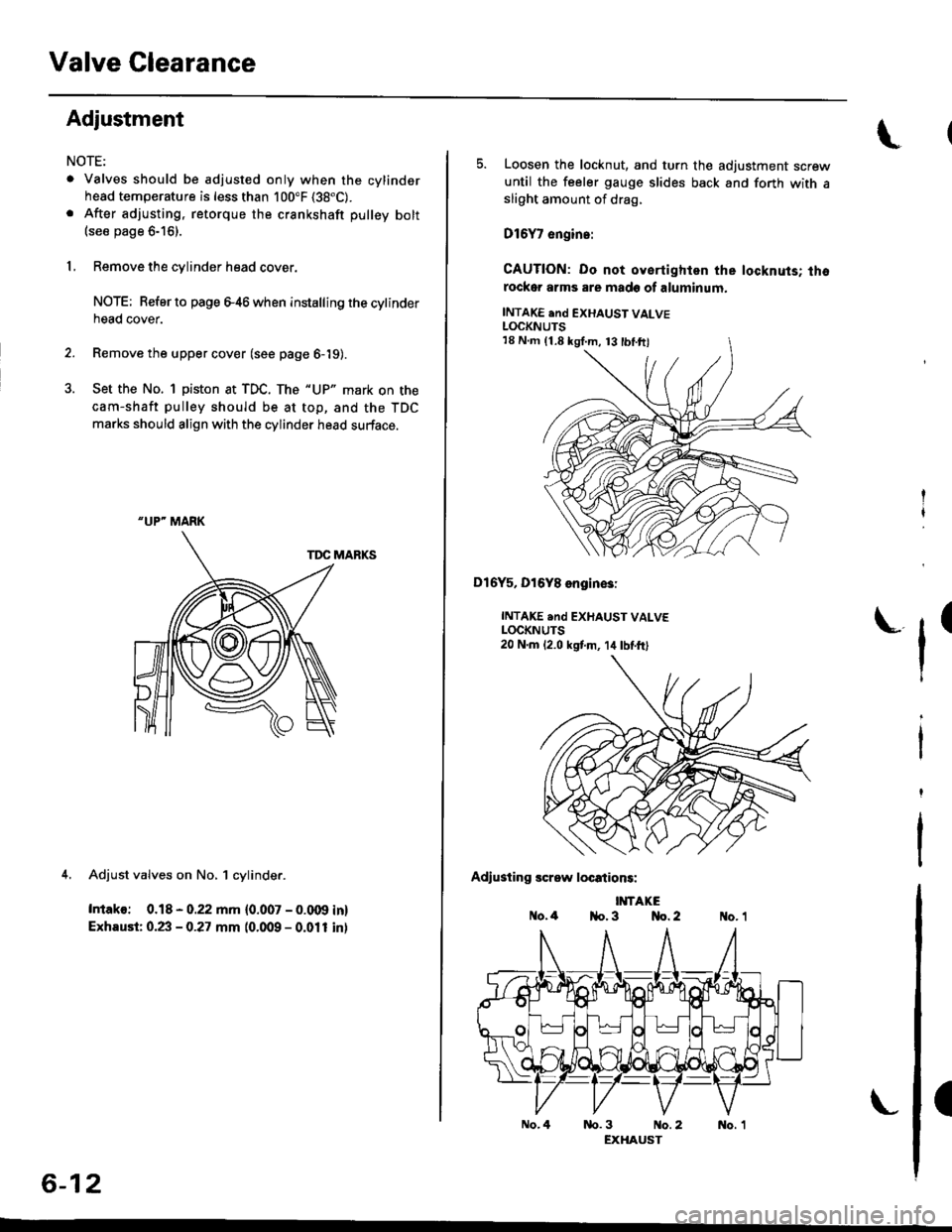
3. Set the No. 1 piston at TDC. The "UP" mark on the
cam-shaft pulley should be at top, and the TDC
marks should align with the cylinder head surface.
TDC MARKS
4. Adjust valves on No, 1 cylinder.
Intako: 0.18 - 0.22 mm {0.007 - 0.009 in}
Exhaust: 0.23 - 0.27 mm (0.009 - 0.011 inl
"UP" MARK
6-12
No.4
5. Loosen the locknut, and turn the adjustment screwuntil the feeler gauge slides back and forth with asliOht amount of drag,
D16Y7 engin.:
CAUTION: Do not oyertighlen the locknuts; thorockor arms are made of aluminum.
INTAKE end EXHAUST VALVELOCKNUTS
Dl6Y5, Dl6Y8 engin€3:
INTAKE .nd EXHAUST VALVELOCKNUTS20 N.m 12.0 kstm, 14lbtft)
Adiusting screw locations:
IMTAKEo.4 1{o. 3 No. 2
tr'
(
nb.3 No.2 No. 1EXHAUST
18 N.m (1.8 kgI.m, 13 tbl.ftl
Page 135 of 2189
Cylinder Head
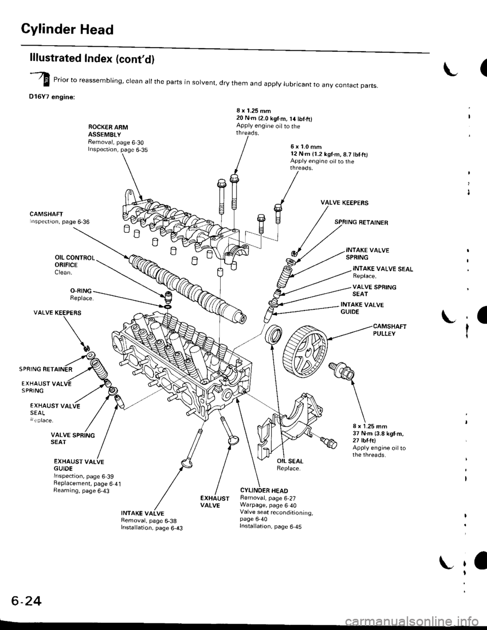
lllustrated Index (cont'dl
(-/) _.- E "or to reassembring, crean at the parts in sorvent, dry them and appry rubricant to anv contact oarts.
D16Y7 engine:
ROCK€R ARMASSEMBLYRemoval, page 6 30Inspection, page 6-35
8 x 1.25 mm20 N.m (2.0 kgt.m, 14 tbt.ftlApply engine oil to the
H
B
O-RINGReplace.
INTAKE VALVE SEALReplace.
VALVE SPRINGSEAT
INTAKE VALVEGUIDE
:a
ti
VALVE
SPRING RETAINER
EXHAUST VALVESEAL
VALVE SPRINGSEAT
EXHAUST VALVEGUIDErnspectron, page 6,39Beplacement, page 6 4lAeaming, page 6-43
8 x 1.25 mm37 N m (3.8 kgt m,27 tbtftlApply engine oiltothe threads.
INTAKE VALVERemoval, page 6-38lnstallation, page 6-43
Removal, page 6,27Warpage, page 6 40Valve seat reconditioning,page 6-40Installation, page 6-45
VALVE
t
t
t
CAMSHAFTnspectron, page 6-36
OIL CONTROLORIFICEClean.
KEEPERS
\
EXHAUST VALSPRING
c -A9-2.+
L
6x1.0mm12 N.m (1.2 kst.m, 8.7 tbf.ft)Apply engine oit to thethreads.
VALVE KEEPERS
SPRING RETAINER
INTAKE VALVESPRING
Page 138 of 2189
Removal
Engine removal is not required for this procedure
!!!s@ Make sure iacks and salety stands are
f ta"eata"ea propetty and hoist brackets are attached to the
correct positions on the engine.
CAUTION:
. Use tender covels to avoid damaging painted sul-
faces.
o To avoid damage, unplug the wiling connectors
carefully while holding the connector portion to
avoid damage.
. To avoid damaging the cylinder head, wait until the
engine coolant temperature drops below 100"F
{38"C} before loossning the tetaining bolts.
NOTE:
o Mark all wiring and hoses to avoid misconnectlon
Also, be sure that they do not contact other wiring or
hoses, or interfere with other parts.
. Inspect the timing belt before removing the cylinder
h ead.
. Turnthe crankshaft pu lley so that the No. lpistonisat
top dead center (see Page 6-21)
'1. Disconnect the negative terminal from the battery'
Drain the engine coolant (see page'10-7).
a Remove the radiator cap to speed draining.
Remove the intake air duct and air cleaner housing
(see page 5 3).
Remove the mounting bolt and lock bolt. then
remove the power steering (P/S) pump belt and
pump (see page 5'5).
Loosen the idler pulley center nut and adjusting
bolt' then remove the air conditioning (A'lc) com-
pressor belt (see Page 5-6).
Loosen the mounting nut and lock bolt. then
remove the alternator belt (see page 6-19).
Remove the P/S pump bracket (see page 5-12).
3.
4.
2.
6.
1.
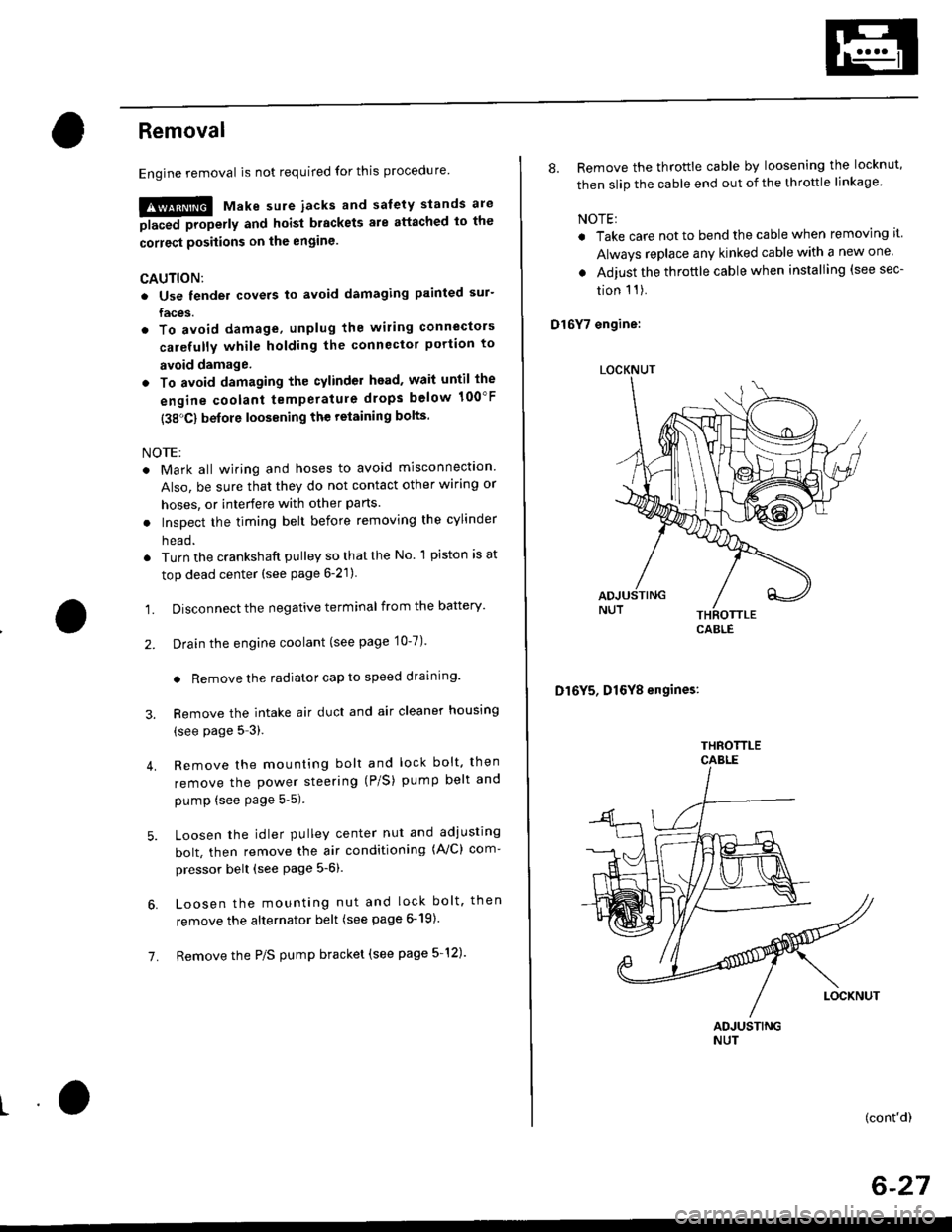
8. Remove the throttle cable by loosening the locknut,
then slip the cable end out of the throttle linkage
NOTE:
. Take care not to bend the cable when removing it
Always replace any kinked cable with a new one
. Adjust the throttle cable when installing (see sec-
tion 1 1).
D16Y7 engine:
Dl6Y5, Dl6Y8 engines:
THFOTTLECABLE
(cont'd)
6-27
LOCKNUT
CABLE
Page 140 of 2189
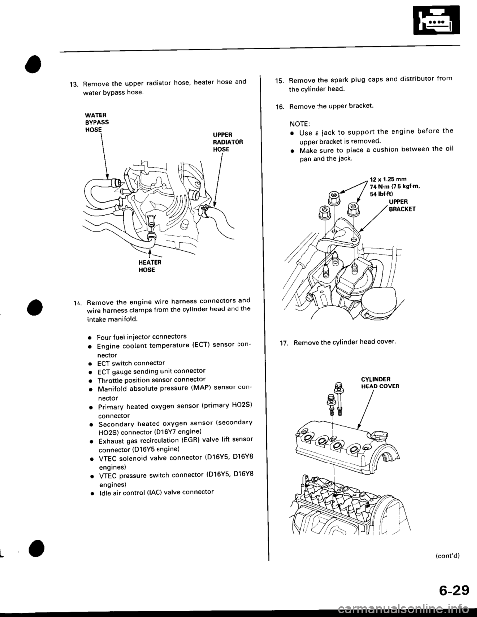
13. Remove the upper radiator hose' heater hose and
water bYPass hose
WATEREYPASSHOSEUPPERRADIATORHOSE
14.
HEATERHOSE
Remove the engine wire harness connectors and
wire harness clamps from the cylinder head and the
intake manifold.
o Four fuel injector connectors
. Engine coolant temperature (ECT) sensor con-
nector
a
a
a
ECT switch connector
ECT gauge sending unit connector
Throttle position sensor connector
Manitold absolute pressure (MAP) sensor con-
nector
Primary heated oxygen sensor (primary HO2S)
connector
Secondary heated oxygen sensor (secondary
HO2S) connector (D16Y7 engine)
Exhaust gas recirculation (EGR) valve lift sensor
connector (D16Y5 engine)
. VTEC solenoid valve connector (Dl6Y5, D16Y8
engrnes)
. VTEC pressure switch connector (D16Y5. D16Y8
engrnes,
. ldle air control (lAC) valve connector
15.Remove the spark plug caps and distributor from
the cylinder head.
Remove the uPPer bracket.
NOTE:
. Use a jack to support the engine before the
upper bracket is removed.
. Make sure to place a cushion between the oil
pan and the jack.
12 x 1.25 mm
74 N.m {7.5 kgf m.
sil lbl.ftl
UPPERBRACKET
'17. Remove the cylinder head cover'
CYLINDERHEAD COVER
(cont'd)
6-29
Page 243 of 2189
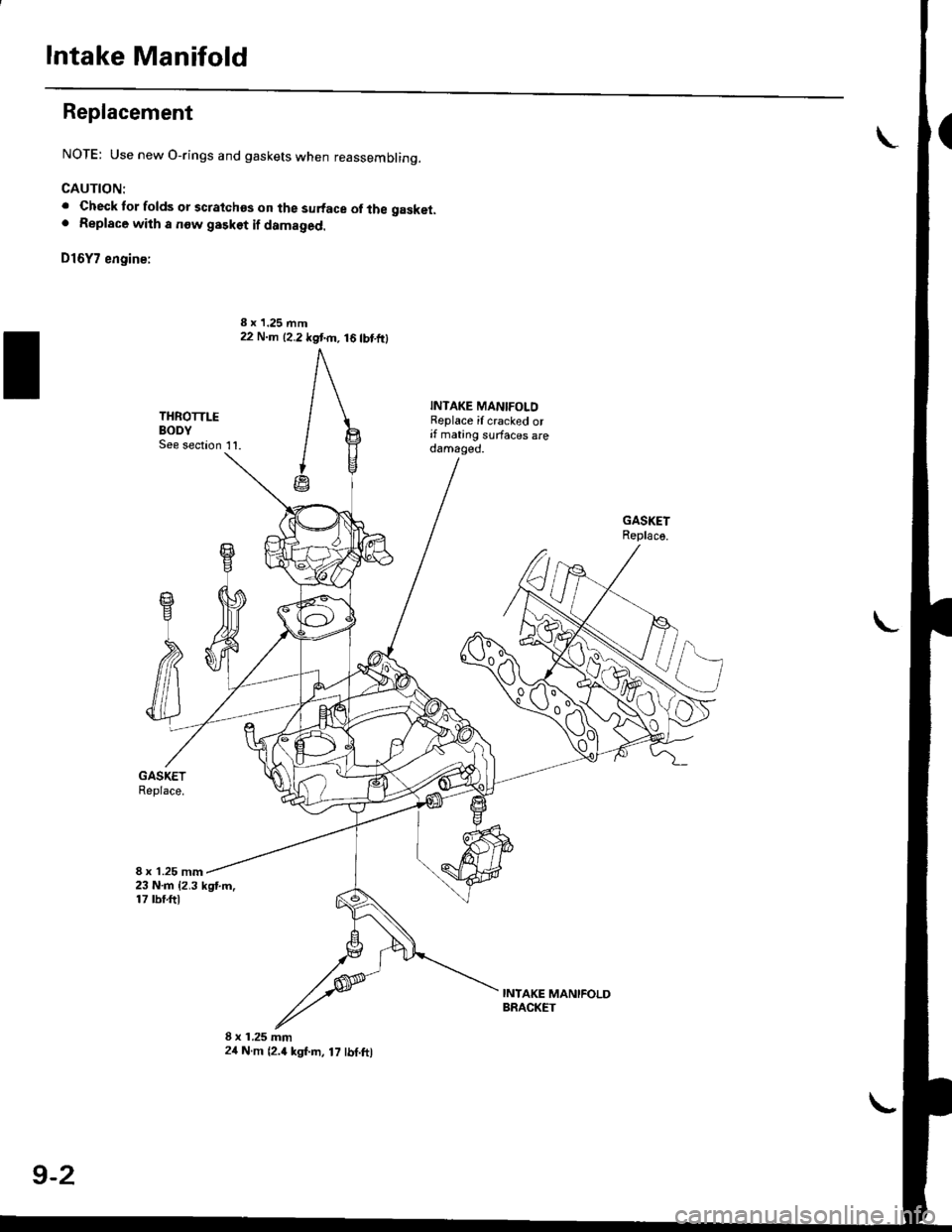
Intake Manifold
Replacement
NOTE: Use new O-rings and gaskets when reassemblinq.
CAUTION:
. Check tor folds or scratchos on the surface of tbe gasket.. Replace with a now gasket if damaged.
D16Y7 engine:
8 x 1.25 mm22 N.m 12.2 kgtm, 16 tbtftl
INTAKE MANIFOLDReplace if cracked orif mating surfaces aredamaged.
8 x 1.25 mm23 N.m {2,3 kgt m.17 rbf.ftl
INTAKE MANIFOLDBRACKET
8 x 1.25 mm24 N.m {2.4 kgf.m, 17 tbf.ftl
9-2
Page 274 of 2189
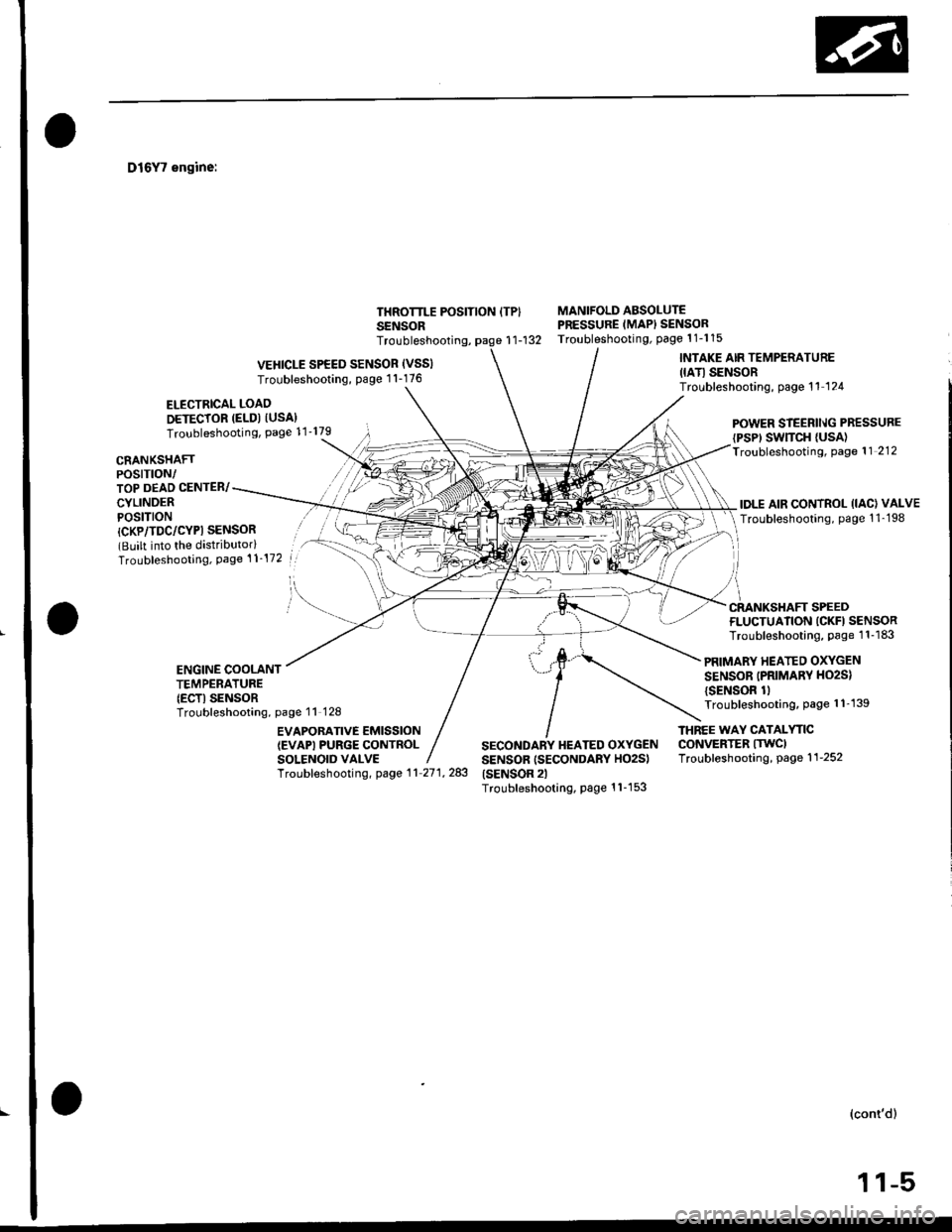
D16Y7 engine:
ELECTRICAL LOAO
DETECTOR (ELD) IUSA}Troubleshooting, Page 11'179
THROTTLE POSITION ITPISENSOR
MANIFOLD ABSOLUTEPRESSURE (MAPI SENSORTroubleshooting, Page 1 1-1 15r1-132
CRANKSHAFTPOSTTTON/TOP DEAD CENTER/
CYLINDERPOSITION
POWER STEERll\lG PRESSURE
{PSP' SWTTCH {USA)Troubleshooting, Page 11 212
IDLE AIR CONTROL (IAC) VALVE
Troubleshooting, page 1 1-198
Troubleshooting,
VEHICLE SPEED SENSOR (VSSI
Troubleshooting, Page 1 1-176
INTAKE AIR TEMPERATURE
IIATI SENSORTroubleshooting, page 11 124
l
/i
CRANKSHAFT SPEED
{CKP/TDC/CYPI SENSOR(Built into the distributorlTroubleshooting, Page 't 1-172
FLUCTUATION ICKFI SENSORTroubleshooting, Page 1 1-183
PRIMARY HEATED OXYGEN
SENSOR (PRIMARV HO2S)
{SENSOR 1lTroubleshooting, page 1 1'139
ENGINE COOLANTTEMPERATURE(ECTI SENSORTroubleshooting, page 11 128
EVAPOBATIVE EMISSION(EVAPI PURGE CONTROLSOLENOID VALVE
THNEE WAY CATALYTICCONVERTER ITWCITroubleshooting, page 1 1-252
Troubf eshooting, page 1 1 27 1, 283
SECONDARY HEATED OXYGENSENSOR (SECONDARY HO2S)(SENSOR 2lTroubleshooting, Page 1 1-1 53
(cont'd)
,l .ltr| | -r,
Page 360 of 2189
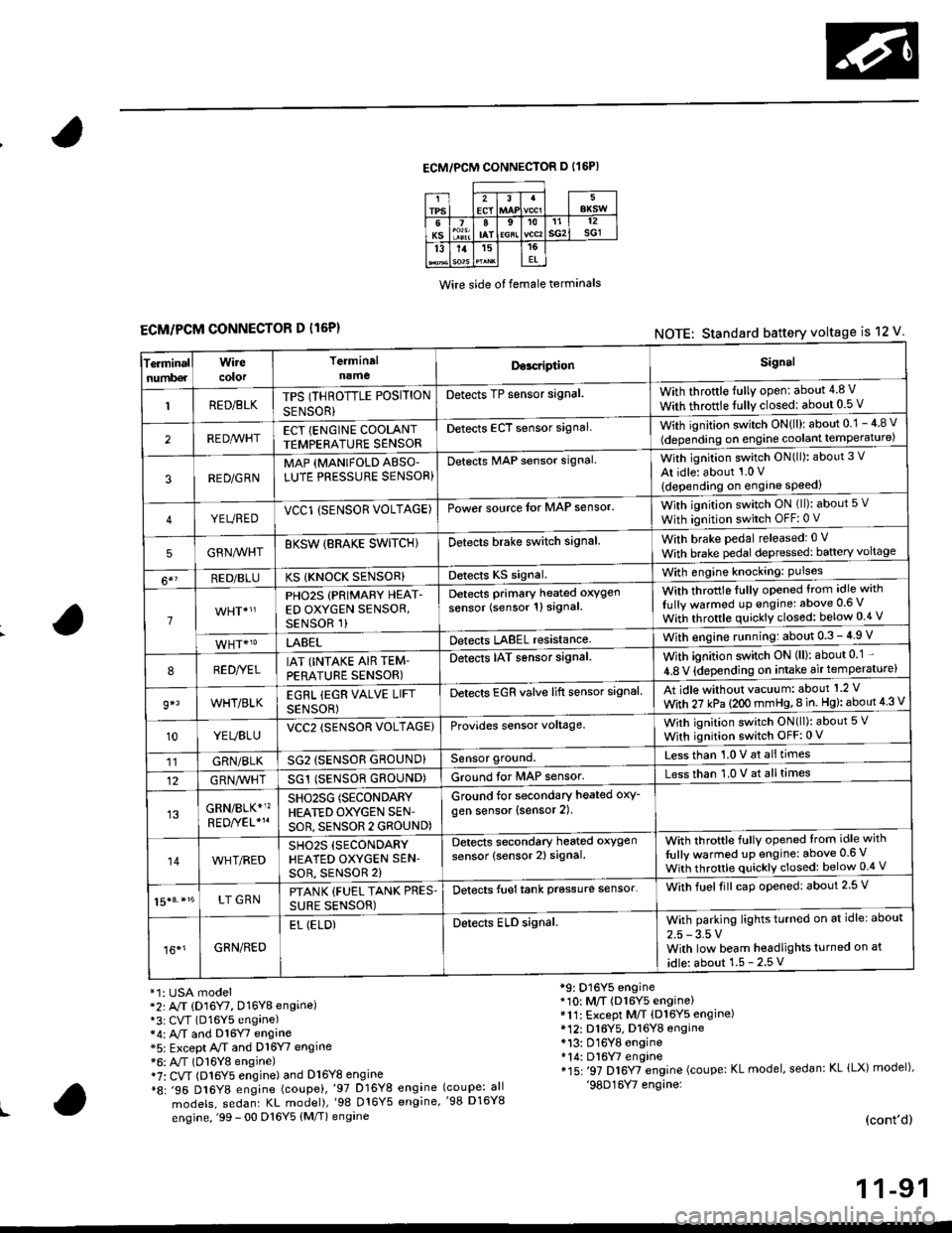
ECM/PCM CONNECTOR D I16P)
Wire side ot female terminals
ECM/PCM CONNECTOR D l16P)NOTE: Standard battery voltage is 12 V
Te.minalnumb€r
Wirecolor
Terminaln!meDor.riptionSignal
RED/BLKTPS (THROTTLE POSITION
SENSOR}
Detects TP sensor signal.With throttle fully open: about 4.8 V
With throttle fully closedl about 0.5 V
REDA/VHTECT {ENGINE COOLANTTEMPERATURE SENSORDetects ECT sensor signalWith ignition switch ON{ll): about 0.1 - 4 8 v
(depending on engine coolant lempe ratu re)
3RED/G RNMAP {MANIFOLD ABSO'LUTE PRESSURE SENSOR}Detects MAP sensor signal.With ignition switch ON(ll): about 3 V
At idle: about 1.0 V
{depending on engine speed)
YEUREDVCCl (SENSOR VOLTAGE)Power source lor MAP sensor.With ignition switch ON (ll): about 5 v
With ignition switch OFF: 0 V
5GRNMHTBKSW {BRAKE SWITCHIDetects brake switch signalWith brake pedal released: 0 v
With brake pedal depressed: baftery voltage
6*?RED/BLUKS {KNOCK SENSOR}Detects KS signal.With engine knocking: Pulses
1
PHO2S (PRIMARY HEAT-ED OXYGEN SENSOR,SENSOR 1)
Detects Primary heated oxygen
sensor (sensor 1l signal
With throttle fullv opened from idle with
Iully warmod up engine: above 0.6 V
With throttle quickly closed: below 0.4 v
LABELDetects LABEL resistanceWith engine r!nning:about 0.3 - 4.9 V
8RED//ELIAT (INTAKE AIR TEM-PERATURE SENSOR)
Detects IAT sensor signal.With ignition switch ON (ll): about 0 1 -
4.8 V {depending on intake air temperature)
9*lWHT/BLKEGRL iEGR VALVE LIFT
SENSOR)
Detects EGR valve lift sensor signalAt idle without vacuum: about'1 2 V
With 27 kPa (2OO mmHg,8 in. Hg): about 4 3 V
10YEUBLUVCC2 (SENSOR VOLTAGE)Provides sensor voltage,With ignition switch ON(ll): about 5 V
With ignition switch OFF:0 V
11GRN/BLKSG2 (SENSOR GROUND}Sensor ground.Less than 1.0 V at alltimes
12G RN,4/1r'HTSG1 (SENSOR GROUND)Ground for MAP sensor.Less than 1.0 V at alltimes
GRN/BLK*1?SHO25G (SECONDARY
HEATED OXYGEN SEN'
SOR, SENSOR 2 GROUND)
Ground for secondary heated oxy-
gen sensor (sensor 2).
14WHT/REDSH02S (SECONDARY
HEATED OXYGEN SEN'soR, sENsoR 2)
Detects secondary heated oxygen
sensor (sensor 2) signal.With throftle fully opened lrom idle with
fully warmed up engine: above 0.6 V
With throttle quickly closed: below 0.4 V
15|3. *15LT GRNPTANK {FUEL TANK PRES.
SURE SENSOR)
Detects fueltank prgssure sensor'With fuelfill caD opened: about 2.5 V
16*1GRN/RED
EL (ELD)Detects ELD signal.With parking lights turned on at idle: about
2.5 - 3.5 VWith low beam headlights turned on at
idle: about 1.5 - 2.5 V
*1: USA model*2r A/T (D16Y7, D16Y8 engine)*3: CVT (D16Y5 engane)*4: A,/T and Dl6Y7 engine*5: Except A/T and D16Y7 engine*6: A"/T (D16Y8 engine)i7: CVT (Dl6Y5 engine) and Dl6Y8 engine*8: .96 D16Y8 engine (coupei,'97 D16Y8 engine
models, sedanr KL model),'98 016Y5 engine,
engine, '99 - 00 D16Y5 (M/T) engine
*9: D16Y5 engine*10: M/T (D16Y5 engine)*11: Except M/T (Dl6Y5 engine)* 12r D16Y5. D16YB engine*13: D16Y8 engine*14: Dl6W engine*15: '97 D16Y7 engine (coupe: KL model, sedan: KL lLX) model),'98D16Y7 engine:(coupe: all'98 D16Y8
(cont'd)
1 1-91
Page 374 of 2189
3.
5.
6.
1.
Fuel Cut-off Control
. During deceleration with the throttle valve closed, current to the fuel injectors is cut off to improve fuel economy at
speeds over the following rpm:. D16Y5 engine (M/T):850 rpm. D]6Y5 engine (CVT), D'16Y8 engine (USA M/T): 920 rpm
. Dl6Y8 engine (USA A,/I), D16Y7 engine (USA A,/T);910 rpm
. D16Y8 engine (Canada M/T), D16Y7 engine (canada): 990 rpm
' D16Y8 engine (Canada M/T): 1,000 rpm
. 816A2 engine: 970 rpm
. Fuel cut-off action also takes place when engine speed exceeds 6,900 rpm (D16Y5, D16Y7 engine; D'16Y8 engine:
7,000 rpm. 816A2 engine: 8.100 rpm), regardless of the position of the throttle valve, to protect the engine from
over-rewing. With '99 Dl6Y7 engine (A,/T) and '99 D16Y8 engine (A./T), the PCM cuts the fuel at engine speeds over
5,000 rpm when the vehicle is not moving.
IVC Compressor Clutch Relay
When the ECM/PCM receives a demand for cooling from the air conditioning system, it delays the compressor from
being energized, and enriches the mixture to assure smooth transition to the A,/C mode
Evaporative Emission (EVAP) Purge Control Solenoid Valve*'
When the engine coolant temperature is above 154'F (68'C). the ECM/PCM controls the EVAP purge control solenoid
valve which controls vacuum to the EVAP purge control canister.
Evaporative Emission (EVAP) Purge Control Solenoid Valve*a
When the engine coolant temperature above 154"F (68"C), intake air temperature above 32"F (0'C) and vehicle speed
above 0 mile (0 km/h) or [Ay'C compressor clutch on and intake air temperature above 160"F (41'C)], the ECM/PCM
controls the EVAP purge control solenoid valve which controls vacuum to the EVAP purge control canister.
Exhaust Gas Recirculation (EGR) Control Solenoid Valve*?
When EGR is required for control of oxides of nitrogen (NOx) emissions. the ECM controls the EGR control solenoid
valve which supplies regulated vacuum to the EGR valve
Alternator Control
The system controls the voltage generated at the alternator in accordance with the electrical load and driving mode,
which reduces the engine load to improve the fuel economy.
ECM/PCM Fail-safe/Back-up Functions
1. Fail safe Function
When an abnormality occurs in a signal from a sensor, the ECM/PCM ignores that signal and assumes a pre-pro-
grammed value for that sensor that allows the engine to continue to run.
2. Back-uD Function
When an abnormality occurs in the ECM/PCM itself, the fuel injectors are controlled by a back-up circuit independent
of the system in order to permit minimal driving.
3. Self diagnosis Function lMalfunction Indicator Lamp (MlL)l
When an abnormality occurs in a signal from a sensor, the ECM/PCM supplies ground for the lvllL and stores the DTC
in erasable memory. When the ignition is initially turned on, the ECM/PCM supplies ground for the MIL for two sec-
onds to check the MIL bulb condition.
4. Two Trip Detection Method
To prevent false indications, the Two Trip Detection Method is used for the HO2S, fuel metering-related. idle control
system, ECT sensor, EGR system and EVAP control system self-diagnostic functions. When an abnormality occurs,
the ECM/PCM stores it in its memory. When the same abnormality recurs after the ignition switch is turned OFF and
ON 0l) again, the ECM/PCM informs the driver by lighting the MlL. However, to ease troubleshooting, this function is
cancelled when you jump the service check connector. The MIL will then blink immediately when an abnormality
occurs,
5. Two (or Three) Driving Cycle Detection Method
A "Driving Cycle" consists ot starting the engine. beginning closed loop operation, and stopping the engine. lf misfir-
ing that increases emissions is detected during two consecutive driving cycles, or TWC deterioration is detected dur-
ing three consecutive driving cycles, the ECM/PCM turns the MIL on. However, to ease troubleshooting, this function
is cancelled when you jump the service check connector. The MIL will then blink immediately when an abnormality
occurs.
(cont'd)
1 1-1 05
.1.
Page 459 of 2189
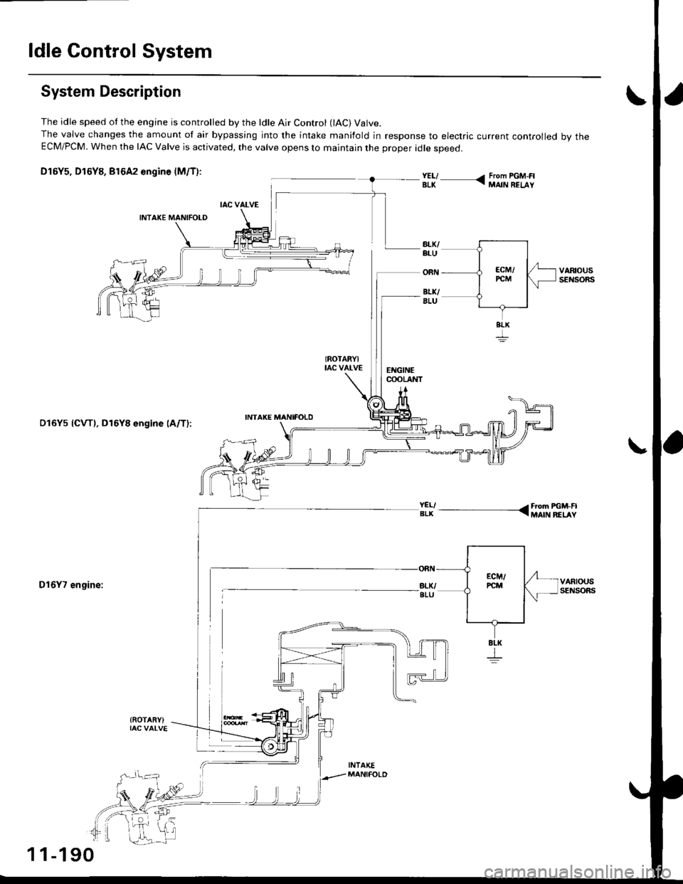
ldle Control System
System Description
The idle speed ot the engine is controlled by the ldle Air Control (lAC) Valve.The valve changes the amount of air bypassing into the intake manifold in response to electric current controlled bv theECM/PCM. When the IAC Valve is activated, the valve opens lo maintain the proper idle speed.
D16Y5, D16Y8, Br6A2 engine (M/T):
(ROTARYItac vat-vEEI{GINEcooLAI{T
VARIOUSsEI{SORS
VARIOUSSENSORS
INTAKE MANIFOTDDl6Ys {CVTl, D16Y8 engine lA/T):
D16Y7 engine:
{ROTABY)
;iy--, - ---
11-190
Page 462 of 2189
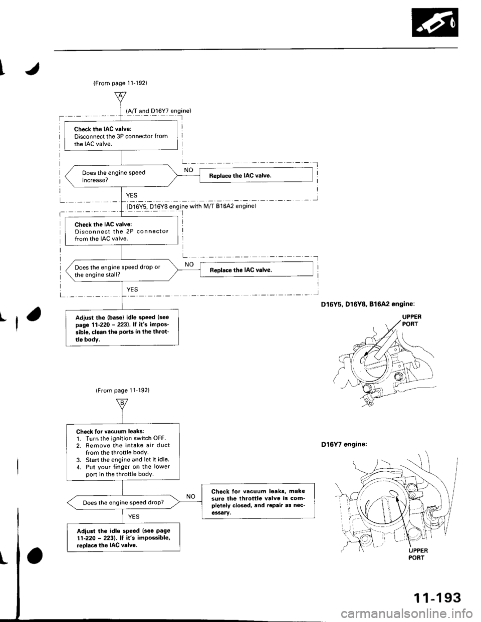
I
L
1D16Y5, D16Y8 engine with M/T 81642 engine)I
D16Y7 engine:
{From page 11-192)
Check the IAC valve:Disconnect the 3P connector from
the IAC valve.
Check the IAC valve:Disconnect the 2P connectorfrom the IAC valve.
Does the engine speed drop or
the engine stall?
Adiust the {base} idle speod (see
page 11-220 - 2231.It it's impos-
aible, clean the ports in lhe throt'
tle bodv,
(From page 11-192i
Check Ior vacuum leaks:1. Turn the ignition switch OFF.2. Remove the intake air ductfrom the throttle body.
3. Start the engine and let it idle.
4. Put your finger on the lowerpon in the th.ottle body.
Ch€ck tor vecuum loaks, m.kesure the throttle valve is com_pletaly closed, end repair as nec-Does the engine speed droP?
Adiust the idle speed (see page
11-220 - 2231. lf it's impossible,
reolace the IAC velve.UPPERPORT
1 1-1 93