Gas throttle HONDA CIVIC 1996 6.G Workshop Manual
[x] Cancel search | Manufacturer: HONDA, Model Year: 1996, Model line: CIVIC, Model: HONDA CIVIC 1996 6.GPages: 2189, PDF Size: 69.39 MB
Page 72 of 2189
ILubrication Points
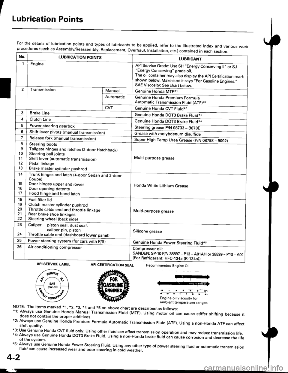
For the details of lubrication points and types of lubricants to be applied, refer to the lllustrated Index and various workprocedures (such as Assembly/Reassembly, Replacement, Overhaul. Installation, etc.) contained in each section.
No.LUBRICATION POINTS
Engine
LUBRICANT
"Energy Conserving" grade oil,The oil container may also display the Apl Certification markshown below. Make sure it says ,,For Gasoline Engines.,,SAE Viscosity: See chart below,
I
TransmissionManualGenuine Honda MTF*1
Genuine Honda Premium FormulaAutomatic Transmission Fluid (ATF)*,
Genuine Honda CVT Fluid*3
Genuine Honda DOT3 Brake Fluid*a
Automatic
CVT
3Brake Line
ClL,tci t""e4
I
Genuine Honda DOT3 Brake Fluid*aPower steering gearboxSteering grease P/N 08733 - BO70EShift lever pivots (manual transmission)Grease with molybdenum disulfide7-:ti
9
10'l'l
l3
14
't7
18
19
20
2122
Release fork (manual trancmi
Shift lever (automatic transmission)Pedal linkageBrake master cylinder pushrod
Super High Temp Urea crease (p/N 08798 - 9OO2)
i Multi-purpose grease
I
I
Honda White Lithium Grease
Multi-purpose grease
Silicone grease
@
Trunk hinges and latch (4-door Sedan and 2-doorCoupe)Door hinges upper and lowerDoor opening detentsHood hinge and hood latch-FUet T ter ttd
Clutch master cylinder pushrodThrottle cable end and throttle linkageRear brake shoe linkagesSteering wheel (back side)
23
E-
Caliper piston seal, dust seal,caliper pin. pistonThrottle cable end (dashboard lower panel)
Power steering system (for cars with p/S)
Air conditioning compressorComDressor oil:SANDEN: SPlo P/N 38897 - p13 -A01AH or 38899 - p13_ A01{For Refrigerant: HFC-134a (R-134a))
CERTIFICATION SEAL
ffi
NorE: The items m arked * 1, *2, +3, *4 and +5 on above chan are described as folows:*1: Always use Genuine Honda Manual Transmission Fluid (MTF). Using motor oil can cause stiffer shifting because itdoes not contain the proper additives.*2: Always use Genuine Honda premium Formula Automatic Transmission Fluid (ATF). Using a non-Honda ATF can affectshift quality.+3: Use Genuine Honda cVTfluid only usingotherfluid can affect tra nsmission operation and may reduce transmission life.*4: Always use Genuine Honda DoT3 Brake Fluid. Using a non-Honda brake fluid can cause corrosion and dec.ease the lifeof the svstem.*5: Always use Genuine Honda Power steering Fluid. using any other type of power steering fluid or automatrc transmissionfluid can cause increased wear and poor steering in cold weather.
4-2
Recommended Engine Oil
Engine oil viscosity forambrent temperature ranges
API SERVICE LABEL
Page 140 of 2189
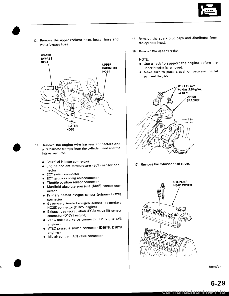
13. Remove the upper radiator hose' heater hose and
water bYPass hose
WATEREYPASSHOSEUPPERRADIATORHOSE
14.
HEATERHOSE
Remove the engine wire harness connectors and
wire harness clamps from the cylinder head and the
intake manifold.
o Four fuel injector connectors
. Engine coolant temperature (ECT) sensor con-
nector
a
a
a
ECT switch connector
ECT gauge sending unit connector
Throttle position sensor connector
Manitold absolute pressure (MAP) sensor con-
nector
Primary heated oxygen sensor (primary HO2S)
connector
Secondary heated oxygen sensor (secondary
HO2S) connector (D16Y7 engine)
Exhaust gas recirculation (EGR) valve lift sensor
connector (D16Y5 engine)
. VTEC solenoid valve connector (Dl6Y5, D16Y8
engrnes)
. VTEC pressure switch connector (D16Y5. D16Y8
engrnes,
. ldle air control (lAC) valve connector
15.Remove the spark plug caps and distributor from
the cylinder head.
Remove the uPPer bracket.
NOTE:
. Use a jack to support the engine before the
upper bracket is removed.
. Make sure to place a cushion between the oil
pan and the jack.
12 x 1.25 mm
74 N.m {7.5 kgf m.
sil lbl.ftl
UPPERBRACKET
'17. Remove the cylinder head cover'
CYLINDERHEAD COVER
(cont'd)
6-29
Page 245 of 2189
lntake Manifold
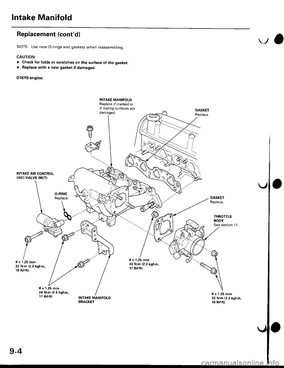
Replacement (cont'dl
NOTE: Use new O,rings and gaskets when reassembling.
CAUTION:
. Check lor folds or scratches on the surface of the gasket.. Replace with a new gasket il damaged.
D16Y8 engine:
INTAKE MANIFOLDReplace if cracked orif mating surfaces areoamageo,
INTAKE AIR CONTROL{ract vAt_vE {M/Tl
GASKETReplace.
8 x 1.25 mm24 N.m {2.{ kgtm.17 tbtftt
THROTTLEBODY
8 x 1.25 mm22 N.rn |.2.2 kgl.rn,16 tbtft)INTAKE MANIFOLDBRACKET
9-4
Page 270 of 2189

!
Fuel and Emrsslons
SoecialToofs .....,...."..,. 11-2
Component Locations
lndex ....................., ......... 11-3
Svstem Description
Vacuum Connections ................,,..,.. ......... 11-12
Electrical Connections ...............,.,.,... ....... 11-29
System Connectors ........,.,.,.......................... 1 1-51
Troubleshooting
Troubleshooting Procedures ................. .. 11-81
Engine Control Module/PowertrainControl Module TerminalAfiangement ....,.,..... 11-88
Diagnostic Trouble Code Chart .................,., 11.97
How to Read Flowcharts .,.......................... . 11-103
PGM-Fl System
System Description ...... 11-10,1
Troubleshooting Flowcharts
Engine Control Module/PowertrainContlol Module ........ 11-107
Manitold Absolute Pressure Sensor .....'. . ... 11-115
fntake Air Temperatuie Sensor ..... . . ., . 11'121
Engine Coolant Temperatuae Sensol ........., 11-128
Throttle Position Sensor ...................,........... 11-132
Primary Heated Orygen Sensor (Sensor 1l ... 11-139
Secondary Heated Oxygen Sensor(Sensor 21.................................................... 1 1-153
Heated Oxygen Sensor Heater ...................,. 11-157
Fuel Supply System ...... 11-164
Random Mislire ......., ..11-166
Misfire Detected in One Cylindsr ................. 11-167
Knock Sensor .,.,............ 11-170
CKP/TDC/CYP Sensor ................................... 11'172
Vehicle Speed Sensor ...........,......,...,.,........... 1t-176
Barometric Pressure Sensor ...............,......... I 1-178
Electrical Load Detector,.,,............................ 1 1-179
CKF Sensor .................... 11-183
ECM/PCM Internal Circuit ............................. I 1-188
A/T Signal {TMA/TMBI .................................. I 1-189
ldle Control System
System Doscriplion ............ 11-190
Troubleshooting Flowcharts
ldle Control System ...... 11-192
ldle Air Control Va1ve .................................... I 1-19i1
Starter Switch Signal .................................... 1 1'202
Air Conditioning Signal ................................. 11'201
Ahernator FR Signal .................................... . 1 1-208
BrakeSwitch Signal ..................................... f 1"210
Power Sleering Prossure Switch Signal ......11-212
A/T Gear Position Signal ............................... 11-216
Clutch Swiich Signal ................................-.... 11-214
ldte Speed Setting . .............11-220
Fuel Supply System
Fuel Lines .,...................,.,.,.,11-221
Fuef Tube/Ouick-Connect Fittings ..........,.,........ 11 -227
System Description ....'.... 11-230
Fuel Pressure .......,.,,........... 11-230
Fuef fniectors ......................11-232
Fu€f Pressure Regulator .....,.......................'...,. 11-231
Fuef Fifter ............................11-235
Fuel Pump .............'.......'.... 11-236
PGM-FI Main Relay .............11'237
Fuel Tank ................ ....,...'.'.' 11'211
Intake Air System
System Description ....-.-.....11-243
Air Cfeaner ...........,......."". .11-211
Throttle Cable .....................11-211
Throttfe Body ........ ..'... . . .,.11-211
Fuel Iniestion Air Control System ,.,.,....-........... 11-250
Emission Control System
System Description .-..........11-252
Taifpip€ Emission ...............11-252
Three Way Catafytic Convert€r ............,.,,.,.,.,.... 11 -252
Exhaust Gas Racirculaiion System ...,.,,,,.,.,.,.,,. 11'254
Positive Crankcas€ Ventilation System .... . . .. 11-266
Evaoorative Emission Controls ..................,,..,.,. 11 -267
Page 272 of 2189
Gomponent Locations
L
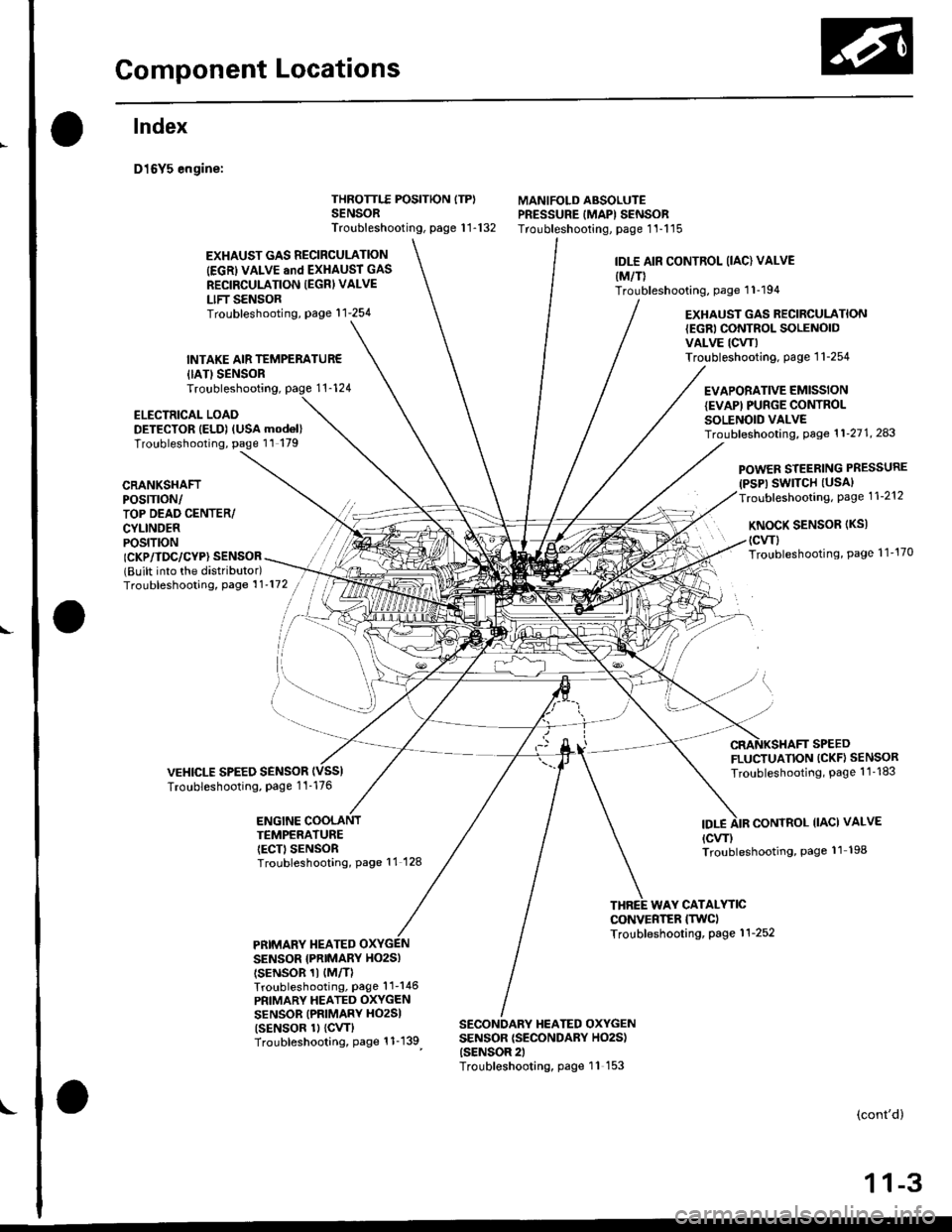
lndex
D16Y5 engine:
{IATISENSORTroubleshooting,
ELECTRICAL LOADDETECTOR IELD) (USA mod6l)Troubleshooting, page 11 179
THROTTLE POSITION ITP)SENSORTroubleshooting, page 1 1-132
MANIFOLD ABSOLUTEPRESSURE IMAPI SENSORTroubleshooting, page 1'l-115
EXHAUST GAS RECIRCULATION
IEGRI VALVE and EXHAUST GAS
RECIRCULATION IEGRI VALVE
LIFT SENSORTroubleshooting, page'l 1-254
INTAKE AIR TEMPERATUR€
IDLE AIR CONTROL (IAC) VALVE
{M/T)Troubleshooting, page 1 1-194
EXHAUST GAS RECIRCULATION{EGRI CONTROL SOLENOIDVALVE ICW)Troubleshooting. page 1 1-254
EVAPORATIVE EMISSIONIEVAPI PUNGE CONTROLSOLENOID VALVETroubf eshooting, Page 1 1'21 1, 243
CRANKSHAFTPOS|TTON/TOP DEAD CENTER/CYLINDERPOS|T|ON
POWER STEERING PRESSURE(PSP) SWITCH (USAI
Troubleshooting, Page 1 1-212
KNoCK SENSoR (Ks)
(cwl
Troubleshooting, Page 1 1'170ICKP/TDC/CYP} SENSOR(Built into the distributor)Troubleshooting, Page 1 1'172
VEHICLE SPEED SENSORTroubleshooting, Page 1 1-176
FLUCTUATION (CKF} SENSOR
Troubleshooting, Page 1 1 -183
ENGINE COOLANTTEMPERATUREIECT) SENSORTroubleshooting, Page 11 128
IDT.ECONTROL IIACI VALVE
{cw)Troubleshooting, Page 11 198
WAY CATALYTICCONVERTER ITWCITroubleshooting, Page 1 1-252PRIMARY TIEATEDSENSOR {PNIMARY HO2SI
tsENsoR 1t {M/TlTroubleshooting, Page'l 1-146
PRIMARY HEATED OXYGENSENSOR (PRIMARY HO2SI
tsENsoR 1l {cw}Troubleshooting, Page 1 1-139
SECONDARY HEATED OXYGENSENSOR {SECONDARY HO2S){SENSOR 2)Troubleshooting, page 11 153
(cont'd)
1 1-3
Page 288 of 2189
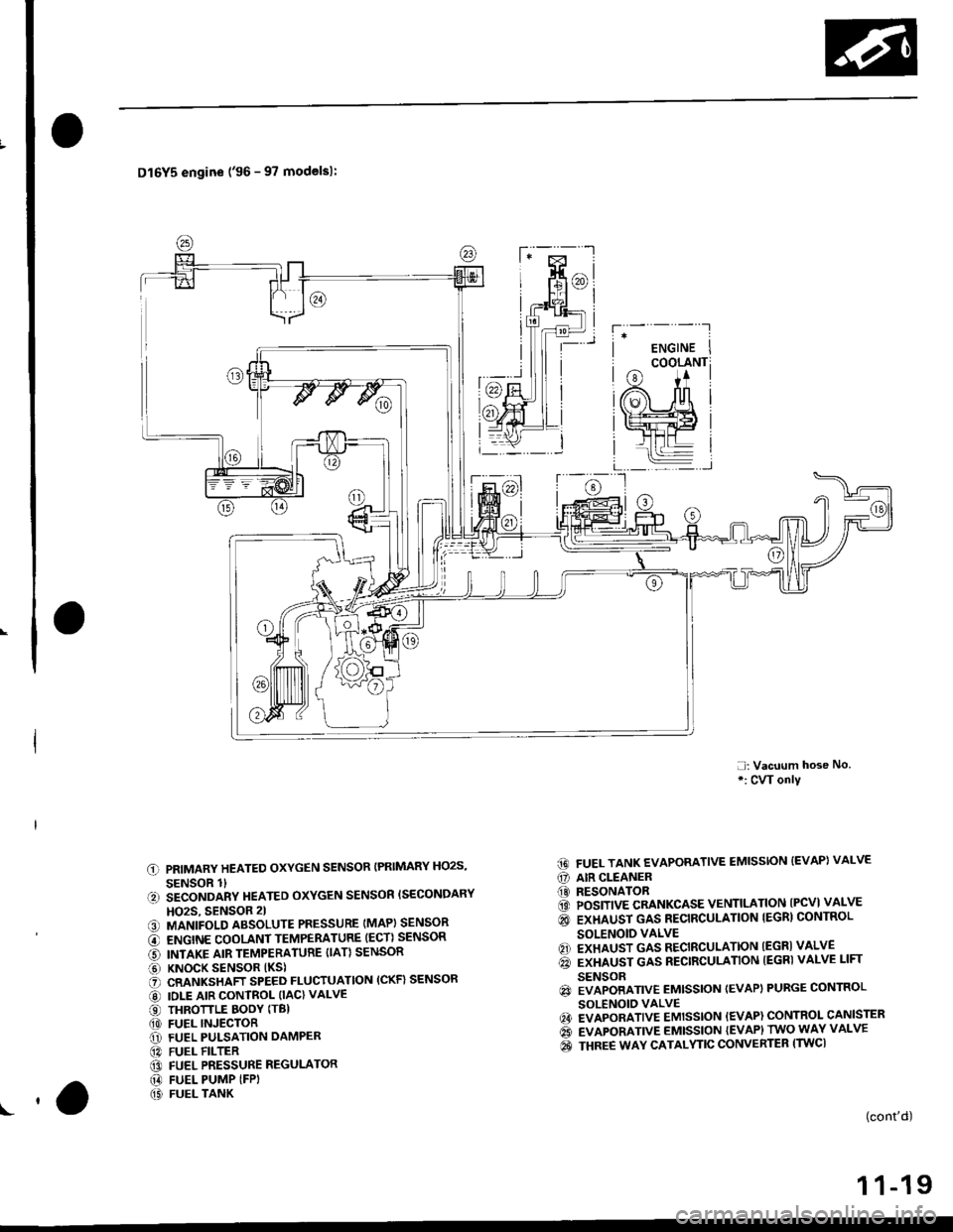
Dl6Y5 engine ('96 - 97 modelsl:
o
,6i
@
o@€)@o
@(il(i'
PRIMARY HEATED OXYGEN SENSOR {PRIMARY HO2S,
SENSOR 1'SECONDARY HEATED OXYGEN SENSOR (SECONDARY
HO2S. SENSOR 2l
MANIFOLD ABSOLUTE PRESSURE {MAP) SENSOR
ENGINE COOLANT TEMPERATURE (ECTI SENSOR
INTAKE AIR TEMPERATURE IIAT) SENSOR
KNOCK SENSOR (KS)
CRANKSHAFT SPEED FLUCTUATTON (CKF} SENSOR
IOLE AIR CONTROL (IAC} VALVE
THROTTLE BODY (TBI
FUEL INJECTORFUEL PULSATION DAMPER
FUEL FILTERFUEL PRESSURE REGULATORFUEL PUMP IFPIFUEL TANK
:li Vacuum hose No*: CVT only
FUEL TANK EVAPORATIVE EMISSTON {EVAP) VALVE
AIR CLEANERRESONATORPOSITIVE CRANKCASE VENTIL/ATION IPCVI VALVE
EXHAUST GAS RECIRCULATION IEGR) CONTROL
SOLENOID VALVEEXHAUST GAS RECIRCULATION (EGRI VALVE
EXHAUST GAS RECTRCULATION IEGRI VALVE LIFT
SENSOREVAPORATIVE EMISSION IEVAPI PURGE CONTROL
SOLENOID VALVEEVAPORATIVE EMISSION {EVAP} CONTROL CANISTER
EVAPORATIVE EMISSION {EVAP} TWO WAY VALVE
THREE WAY CATALYTIC CONVERTER (TWCI
{Do(D
@@
@@
@
@@@
(cont'd)
1 1-19
!'a
Page 289 of 2189
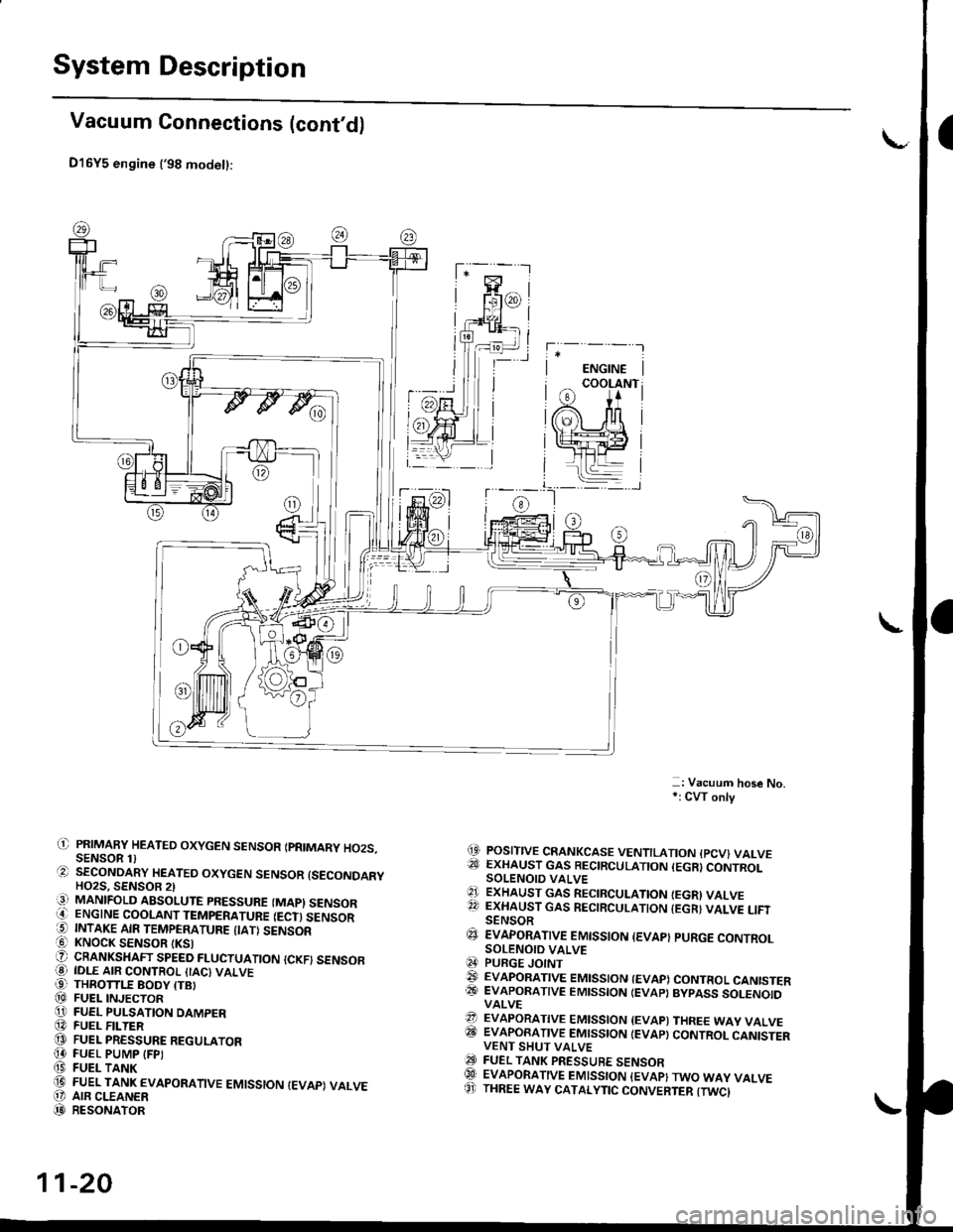
System Description
Vacuum Connections (cont'd)
D16Y5 engine ('98 modet):
-: Vacuum hose No,*: CW only
(9 POSITIVE CRANKCASE VENTILATION {PCV} VALVE?!J EXHAUST GAS BECIRCULATION (EGR}CONTROLSOLENOIO VALVE'1 ExHAUST GAs RECIRCULATIoN IEGRI VALVE22 EXHAUST GAS RECIRCULATION {EGR} VALVE LIFISENSOR€J EvApoRATtvE EMtsstoN {EvAp} puRGE coNTRoLSOLENOID VALVEq4 PURGE JOINT@ EVAPoRATIVE EMIssIoN {EVAP) coNTRoL CANISTER@� EVAPORATIVE EMISSION IEVAP} BYPASS SOLENOIDVALVE?? EVAPORATIVE EMISSION {EVAP) THREE WAY VALVEITII EVAPORATIVE EMISSION IEVAP} CONTROL CANISTERVENT SHUT VALVEO FUEL TANK PRESSURE sENsoRQlI EVAPORATIVE EMISSION {EVAP}TWO WAY VALVE8' THREE WAY CATALYTIC CONVERTER {TWCI
il) PRIMAFY HEATED OXYGEN SENSOR IPRIMARY HO2S.SENSOR 1)O SECoNDARY HEATEo oxYGEN sENsoR {sEcoNDARYHO2S. SENSOB 2)iq] MANIFOLD ABSOLUTE PRESSURE (MAPI SENSORO ENGINE COOLANT TEMPERATURE IECT) SENSOR5 INTAKE AIR TEMPERATURE {IATI SENSOR! KNOCK SENSOR tKSlO CRANKSHAFT SPEED FLUCTUATIoN {cKF) sENsoFO IDLE AIR coNTRoL {IAc) vALvE99 THROTTLE BODY ITBI@ FUEL INJECToRO FUEL PULSATION DAMPER@ FUEL F -TER@ FUEL PRESSURE REGULAToR[4 FUEL PUMP IFPI(9 FUEL TANK(D FUEL TANK EVAPoRATIVE EMIssIoN IEVAPI VALVEO' AIR CLEANER(D RESoNAToR
11-20
Page 290 of 2189
![HONDA CIVIC 1996 6.G Workshop Manual D16Y5 engine (99 - 00 modelsl:
O) PRIMARY HEATED OXYGEN SENSOR (PBIMARY HO2S,
SENSOR 1)
O SECONDARY HEATEO OXYGEN SENSOR {SECONDARY
HO2S. SENSOR 2)
6] MANIFOLD ABSOLUTE PRESSURE IMAPI SENSOR
rO CruCI HONDA CIVIC 1996 6.G Workshop Manual D16Y5 engine (99 - 00 modelsl:
O) PRIMARY HEATED OXYGEN SENSOR (PBIMARY HO2S,
SENSOR 1)
O SECONDARY HEATEO OXYGEN SENSOR {SECONDARY
HO2S. SENSOR 2)
6] MANIFOLD ABSOLUTE PRESSURE IMAPI SENSOR
rO CruCI](/img/13/6068/w960_6068-289.png)
D16Y5 engine ('99 - 00 modelsl:
O) PRIMARY HEATED OXYGEN SENSOR (PBIMARY HO2S,
SENSOR 1)
O SECONDARY HEATEO OXYGEN SENSOR {SECONDARY
HO2S. SENSOR 2)
6] MANIFOLD ABSOLUTE PRESSURE IMAPI SENSOR
rO CruCIruC COOUruT TEMPERATURE IECTI SENSOR
o rrurlxe ln ETUpERATURE 0AT) SENSOR
.d KNOCK SENSOR (KS}
O CN,NruXSXITT SP:ED FLUCTUATION (CKFI SENSOR
@ rou an corurnoL 0Ac) valvE
O THROTTLE BODY (TB)
@ FUEL INJECTOR
E) FUEL PULSATION OAMPER
t? FUEL FILTER
G) FUEL PRESSURE REGULATOR
OI FUEL PUMP (FP)
Gi FUEL TANK
G) AIR CLEANERfi? RESONATOR
Gl posmvr cnglrcAsE VENTILATION (PCV) VALVE
@ EXHAUST GAS RECIRCULATION IEGR} CONTROL
SOLENOID VALVE6 EXHAUST GAS RECTRCULATION (EGR) VAI-VE
rf exxlust cls nectRcuLATloN IEGR) vALvE LIFT
SENSOR@ EVAPORATIVE EMISSION (EVAPI PURGE CONTNOL
SOLENOID VALVE
O} PURGE JOINTio :vaponanve eutssloN (EVAP) coNTRoL cANlsrER
d rvlponlrtve EmtsstoN tEvAPl BYPASS soL-eNolD
VALVE
6 EVAPORATIVE EMISSION {EVAP) CONIROL CANISTER
FILTER
@ EVAPORATIVE EMISSION (EVAPI CONTROL CANISTER
VENT SHUT VALVEOA FUEL TANK PRESSURE SENSOR
6 :vlponlnvg er,/tlssloN tEvAPl TWO WAY VALVE
6 oNgoano nerueltNc vAPoR REcovERY {onvRl VENT
SHUT VALVE
€!) ONBOARD REFUELING VAPOR RECOVERY (ORVRI VAPOR
RECIBCULATION VALVE
@ THREE WAY CATALYTIC CONVERTER (TWCI
(cont'd)
11-21
L
Page 374 of 2189
3.
5.
6.
1.
Fuel Cut-off Control
. During deceleration with the throttle valve closed, current to the fuel injectors is cut off to improve fuel economy at
speeds over the following rpm:. D16Y5 engine (M/T):850 rpm. D]6Y5 engine (CVT), D'16Y8 engine (USA M/T): 920 rpm
. Dl6Y8 engine (USA A,/I), D16Y7 engine (USA A,/T);910 rpm
. D16Y8 engine (Canada M/T), D16Y7 engine (canada): 990 rpm
' D16Y8 engine (Canada M/T): 1,000 rpm
. 816A2 engine: 970 rpm
. Fuel cut-off action also takes place when engine speed exceeds 6,900 rpm (D16Y5, D16Y7 engine; D'16Y8 engine:
7,000 rpm. 816A2 engine: 8.100 rpm), regardless of the position of the throttle valve, to protect the engine from
over-rewing. With '99 Dl6Y7 engine (A,/T) and '99 D16Y8 engine (A./T), the PCM cuts the fuel at engine speeds over
5,000 rpm when the vehicle is not moving.
IVC Compressor Clutch Relay
When the ECM/PCM receives a demand for cooling from the air conditioning system, it delays the compressor from
being energized, and enriches the mixture to assure smooth transition to the A,/C mode
Evaporative Emission (EVAP) Purge Control Solenoid Valve*'
When the engine coolant temperature is above 154'F (68'C). the ECM/PCM controls the EVAP purge control solenoid
valve which controls vacuum to the EVAP purge control canister.
Evaporative Emission (EVAP) Purge Control Solenoid Valve*a
When the engine coolant temperature above 154"F (68"C), intake air temperature above 32"F (0'C) and vehicle speed
above 0 mile (0 km/h) or [Ay'C compressor clutch on and intake air temperature above 160"F (41'C)], the ECM/PCM
controls the EVAP purge control solenoid valve which controls vacuum to the EVAP purge control canister.
Exhaust Gas Recirculation (EGR) Control Solenoid Valve*?
When EGR is required for control of oxides of nitrogen (NOx) emissions. the ECM controls the EGR control solenoid
valve which supplies regulated vacuum to the EGR valve
Alternator Control
The system controls the voltage generated at the alternator in accordance with the electrical load and driving mode,
which reduces the engine load to improve the fuel economy.
ECM/PCM Fail-safe/Back-up Functions
1. Fail safe Function
When an abnormality occurs in a signal from a sensor, the ECM/PCM ignores that signal and assumes a pre-pro-
grammed value for that sensor that allows the engine to continue to run.
2. Back-uD Function
When an abnormality occurs in the ECM/PCM itself, the fuel injectors are controlled by a back-up circuit independent
of the system in order to permit minimal driving.
3. Self diagnosis Function lMalfunction Indicator Lamp (MlL)l
When an abnormality occurs in a signal from a sensor, the ECM/PCM supplies ground for the lvllL and stores the DTC
in erasable memory. When the ignition is initially turned on, the ECM/PCM supplies ground for the MIL for two sec-
onds to check the MIL bulb condition.
4. Two Trip Detection Method
To prevent false indications, the Two Trip Detection Method is used for the HO2S, fuel metering-related. idle control
system, ECT sensor, EGR system and EVAP control system self-diagnostic functions. When an abnormality occurs,
the ECM/PCM stores it in its memory. When the same abnormality recurs after the ignition switch is turned OFF and
ON 0l) again, the ECM/PCM informs the driver by lighting the MlL. However, to ease troubleshooting, this function is
cancelled when you jump the service check connector. The MIL will then blink immediately when an abnormality
occurs,
5. Two (or Three) Driving Cycle Detection Method
A "Driving Cycle" consists ot starting the engine. beginning closed loop operation, and stopping the engine. lf misfir-
ing that increases emissions is detected during two consecutive driving cycles, or TWC deterioration is detected dur-
ing three consecutive driving cycles, the ECM/PCM turns the MIL on. However, to ease troubleshooting, this function
is cancelled when you jump the service check connector. The MIL will then blink immediately when an abnormality
occurs.
(cont'd)
1 1-1 05
.1.
Page 403 of 2189
PGM-FI System
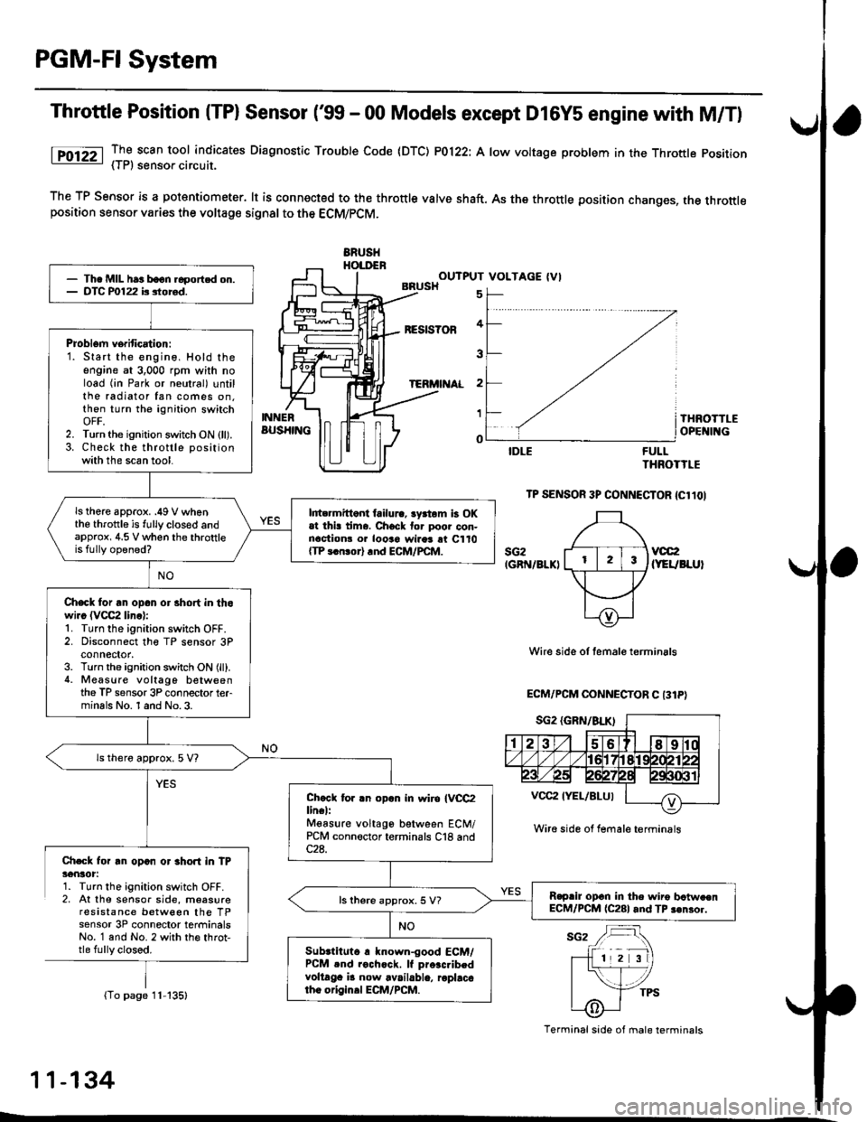
Throttle Position (TPl Sensor ('99 - 00 Models except D16Y5 engine with M/T)
lTO12Z _TI scan tool indicates Diaqnosttc Trouble Code (DTC) P0122: A low voltage problem in the Throttle position- { | r, sensoa crrcurl.
The TP Sensor is a potantiometer. lt is connected to the throttle valve shaft. As the throttle position changes, the throttleposition sensor varies the voltage signal to the ECM/PCM.
ERUSHHOI.DENOUTPUT VOLTAGE (VIBRUSH
BESIS?OF
TERi'I AL
5
4
3
2
1
o
INNERBUS}IINGTHROTTLEOPE II{G
FULLTHROTTLE
TP SENSOR 3P CONNECTOR {Cl1OI
sG2IGRN/8LKIvcc2(YEUBLUI
Wire side of temale terminals
ECM/PCM OONNECTOR C 131P)
Ch.Gk for rn opan or 3hort in TP36nlot:1. Turn the ignition switch OFF.2, At the sensor side, moasureresistance between the TPsensor 3P connector terminalsNo. 1 and No. 2 with th€ throt,tle fully closed.
(To page 11-135)
- Th. MIL har boon.6portcd on.- DTC P0122 b siored.
Problem verification:1. Start the engine, Hold theengine at 3,000 rpm with noload (in Park or neutral) untilthe radiator fan comes on.then turn the ignition switchOFF,2. Turn the ignition switch ON (ll).3. Check the throttle positionwith the scan tool.
ls there approx. .49 V whenthe throttle is fully clos€d andapprox, 4.5 V when the throttleis fully opened?
l||t rmittont failura, lyrtom b OKat thi! tima. Chock tor poor con-nactionr o. looao wires rt C110{TP 3.n!or} rnd ECM/PCM.
Check for an opan or 3hort in thowi.c (VCC2 linc):1. Turn the ignition switch OFF.2. Disconnect the TP sensor 3Pconnector,3. Turn the ignition switch ON (ll).4. Measure voltago betweenthe TP sensor 3P connector terminals No. 1 and No.3.
ls thero approx. 5 V?
Chccl tor .n opln in wiro IVCC2lin€l:Mgasure voltago between ECM/PCM connector terminals C18 and
R.prir opcn in the wiro bctw.enECM/PCM (C281 and TP 3€nror.ls there approx. 5 V?
Subrtituto r known-good ECM/PCM .nd rochcck. lf pro.c.ibedvoltaga i! now available, roplacotho origin.l ECM/PCM.
Wire side ol female terminrls
Terminal side of male terminals
11-134
L