Hose connection HONDA CIVIC 1996 6.G Workshop Manual
[x] Cancel search | Manufacturer: HONDA, Model Year: 1996, Model line: CIVIC, Model: HONDA CIVIC 1996 6.GPages: 2189, PDF Size: 69.39 MB
Page 177 of 2189
Removal
Engine removal is not required for this procedure.
!@@ Make sure jacks and safety stands are placed
properly and hoist brackels are attached to correst posi-
tion on the engine,
CAUTION:
o Use fender covers to avoid damaging painted sur-
faces.
To avoid damage, unplug the wiling connectors
carelully while holding the connector portion.
To avoid damaging the cylinder head, wait until the
engine coolant temperature drops below 100"F {38'Cl
before loosening the retaining bolt.
NOTE:
. Unspecified items are common.
. Mark all wiring and hoses to avoid misconnection.
AIso, be sure that they do not contact other wiring or
hoses or interfere with other parts.
o Inspect the timing belt before removing the cylinder
n eao.
. Turn the crankshaft pulley so that the No. 1 piston is
at top dead center (see page 6-64).
1. Disconnect the negative terminal from the battery.
Drain the engine coolant {see page 10-7).
. Remove the radiator cap to speed draining.
Remove the strut brace (see page 5-2).
Remove the intake air duct and air cleaner housing
(see page 5-3).
Remove the adjusting bolt and mounting bolt, then
remove the power steering (P/S) pump belt and pump
(see page 5 5).
2.
3.
4.
\
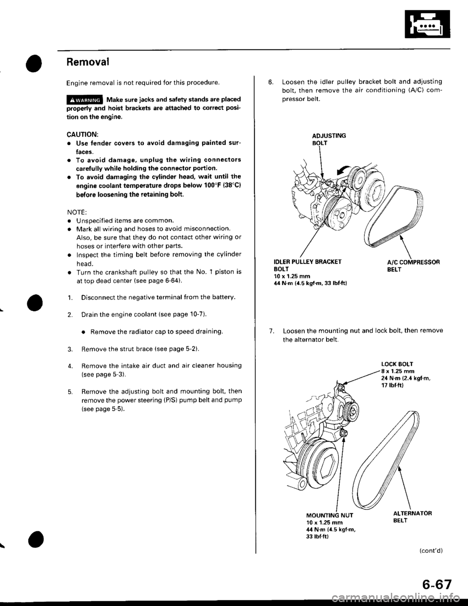
ADJUSTING
6. Loosen the idler pulley bracket bolt and adjusting
bolt, then remove the air conditioning (A/C) com-
pressor belt.
IDLER PULLEY BRACKETBOLT10 x 1.25 mm44 N.m {4.5 kg,l.m, 33 lbt.ft}
7. Loosen the mounting nut and lock bolt, then remove
the alternator belt.
LOCK BOLT8 x 1.25 mm24 N.m {2.4 kgf.m,17 tbtftl
ALTERNATORBELT10 x 1.25 mm,l,l N.m {4.5 kgf.m,33 tbf.ft,
(cont'd)
6-67
Page 258 of 2189
lv
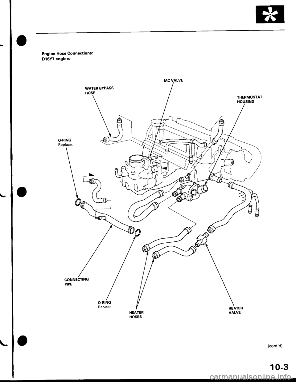
Engine Hose Connections:
D15Y7 engine:
CONNECTINGPIPE
HEATERHOSES
{cont'd)
IAC VALVE
WATEF BYPASS
THERMOSTATHOUSING
VALVE
10-3
Page 259 of 2189
lllustrated Index
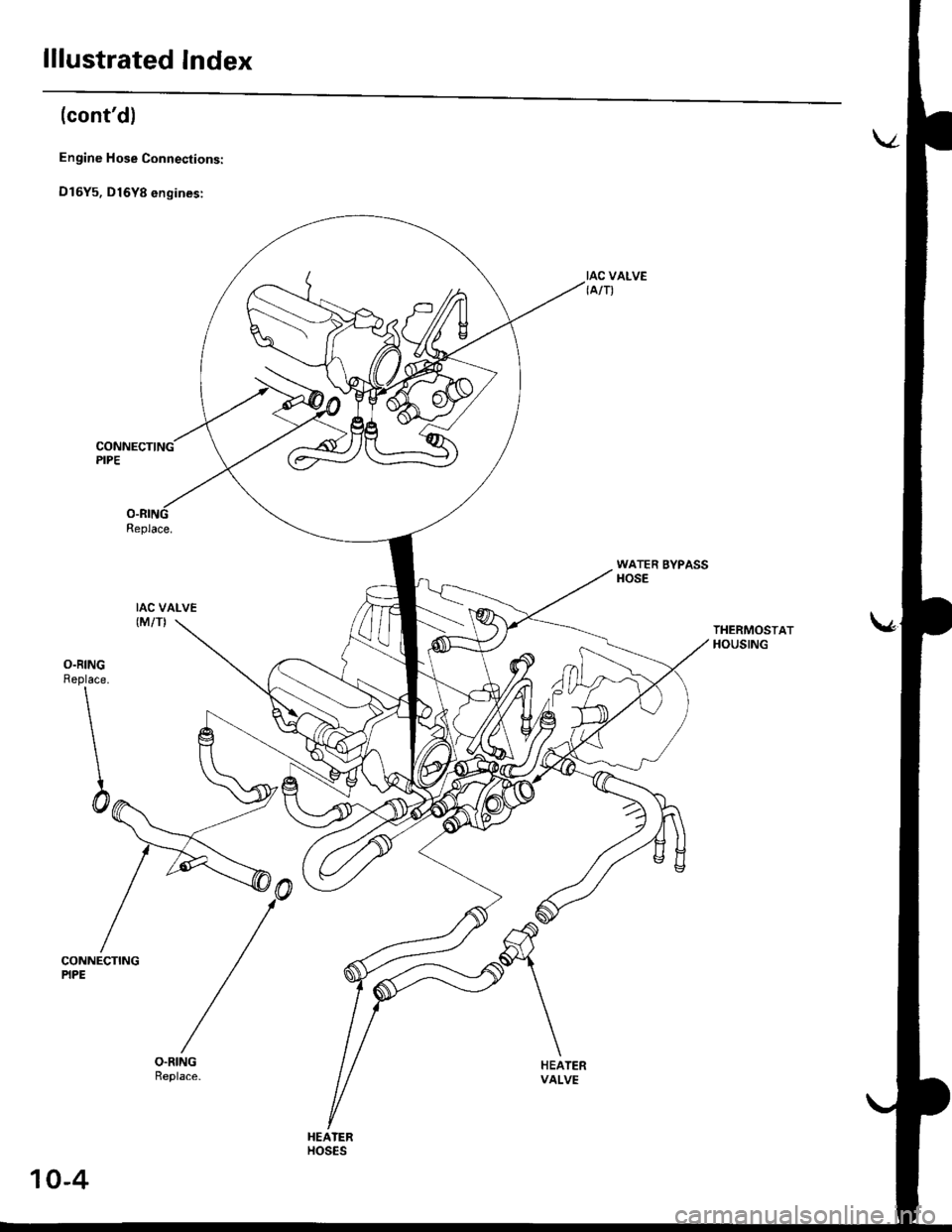
(cont'd)
Engine Hose Connections:
D16Y5, D16Y8 engines:
Replace.
IAC VALVE(M/TI
IAC VALVE{A/T)
WATER BYPASSHOSE
THERMOSTATHOUSING
O.RINGReplace.
\
\
\
\h
CONNECTINGPIPE
HEATERVALVE
HEATERHOS€S
10-4
Page 281 of 2189
System Description
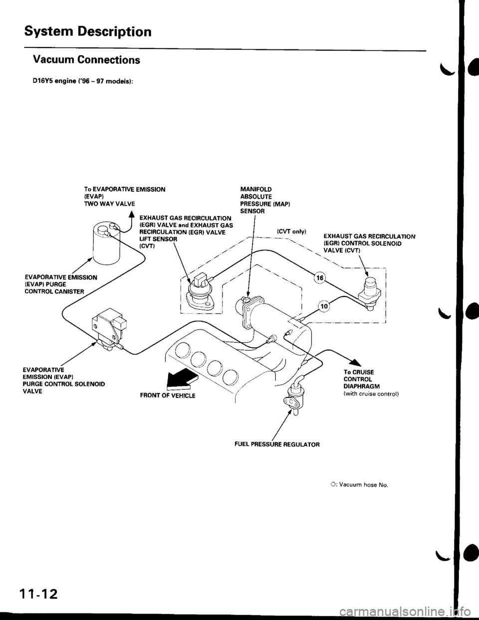
Vacuum Connections
D16Y5 engin6 ('96 - 97 modelsl:
To EVAPORATIVE EMISSION(EVAPI
TWO WAY VALVE
MANIFOLDABSOLUTEPRESSURE IMAPISENSOR
€VAPORATIVEEMISSION IEVAPIPURGE CONTROL SOLENOIDVALVE
EXHAUST GAS BECIRCULATION(EGR) VALVE end EXHAUST GASRECIRCULATION IEGR) VALVELIFT SENSOR
Qo
FRONT OF VEHICLE
To CRUISECONTROLDIAPHRAGM(wath cruise control)
Qo
O: Vacuum hose No.
11-12
EXHAUST GAS RECIRCULATION(EGR) CONTROL SOLENOID VALVE {CVT}\.'.-' \
I
I
)
FUEL PRESSURE REGULATOR
Page 289 of 2189
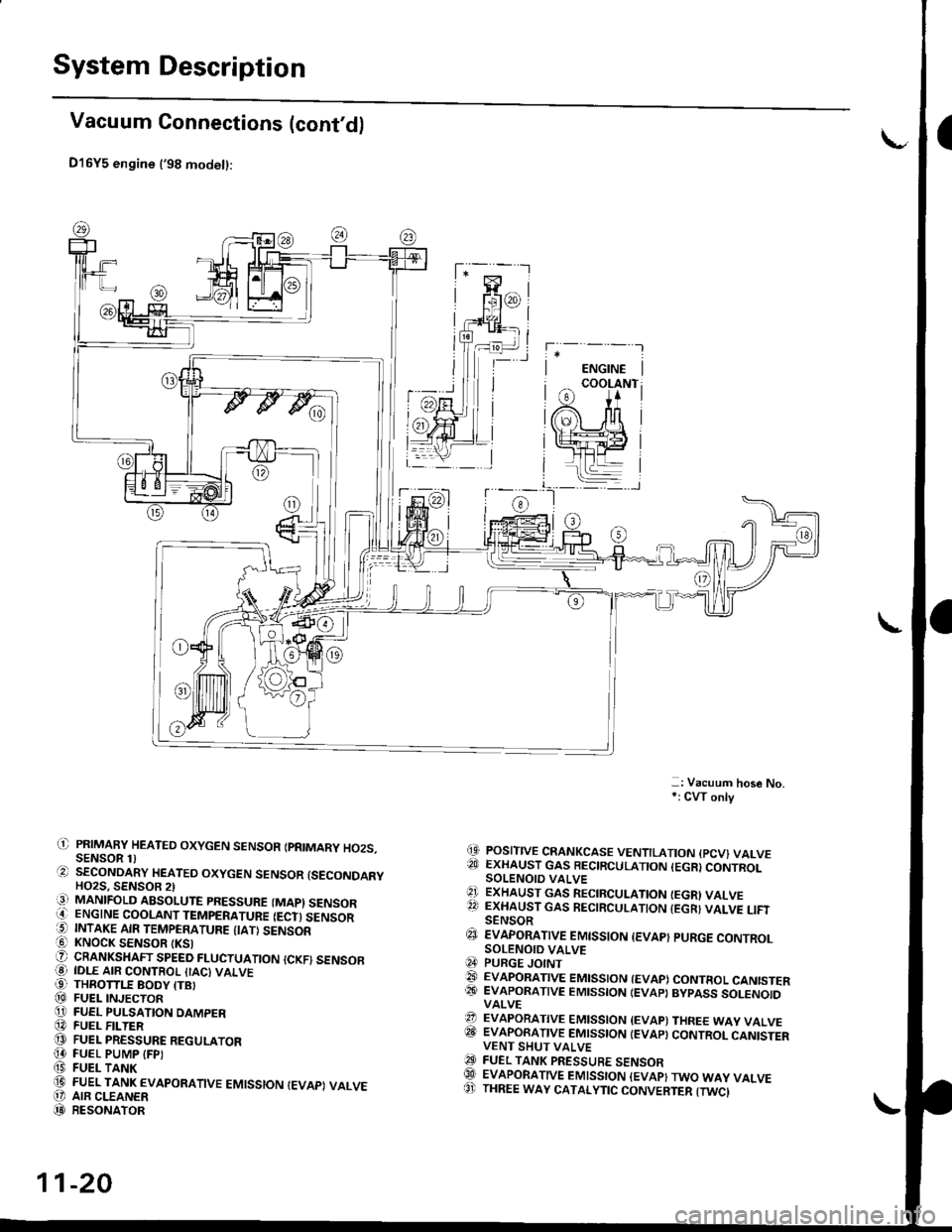
System Description
Vacuum Connections (cont'd)
D16Y5 engine ('98 modet):
-: Vacuum hose No,*: CW only
(9 POSITIVE CRANKCASE VENTILATION {PCV} VALVE?!J EXHAUST GAS BECIRCULATION (EGR}CONTROLSOLENOIO VALVE'1 ExHAUST GAs RECIRCULATIoN IEGRI VALVE22 EXHAUST GAS RECIRCULATION {EGR} VALVE LIFISENSOR€J EvApoRATtvE EMtsstoN {EvAp} puRGE coNTRoLSOLENOID VALVEq4 PURGE JOINT@ EVAPoRATIVE EMIssIoN {EVAP) coNTRoL CANISTER@� EVAPORATIVE EMISSION IEVAP} BYPASS SOLENOIDVALVE?? EVAPORATIVE EMISSION {EVAP) THREE WAY VALVEITII EVAPORATIVE EMISSION IEVAP} CONTROL CANISTERVENT SHUT VALVEO FUEL TANK PRESSURE sENsoRQlI EVAPORATIVE EMISSION {EVAP}TWO WAY VALVE8' THREE WAY CATALYTIC CONVERTER {TWCI
il) PRIMAFY HEATED OXYGEN SENSOR IPRIMARY HO2S.SENSOR 1)O SECoNDARY HEATEo oxYGEN sENsoR {sEcoNDARYHO2S. SENSOB 2)iq] MANIFOLD ABSOLUTE PRESSURE (MAPI SENSORO ENGINE COOLANT TEMPERATURE IECT) SENSOR5 INTAKE AIR TEMPERATURE {IATI SENSOR! KNOCK SENSOR tKSlO CRANKSHAFT SPEED FLUCTUATIoN {cKF) sENsoFO IDLE AIR coNTRoL {IAc) vALvE99 THROTTLE BODY ITBI@ FUEL INJECToRO FUEL PULSATION DAMPER@ FUEL F -TER@ FUEL PRESSURE REGULAToR[4 FUEL PUMP IFPI(9 FUEL TANK(D FUEL TANK EVAPoRATIVE EMIssIoN IEVAPI VALVEO' AIR CLEANER(D RESoNAToR
11-20
Page 460 of 2189
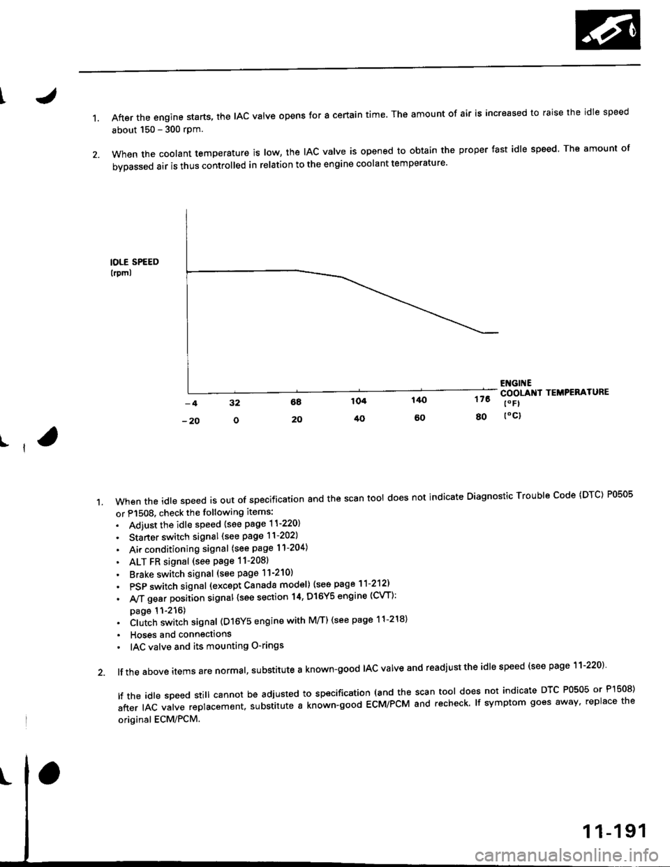
1.After the engine starts, the lAc valve opens for a certain time. The amount of air is increased to raise the idle speed
about 150 - 300 rpm.
When the coolant temperature is tow, the IAC valve is opened to obtain the proper fast idle speed. The amount of
bypassed air is thus controlled in relation to the engine coolant temperature'
IOLE SPEED
lrpml
176
80
ENGI ECOOLANI TEMPERATURE
t" Fl
toc)
ll
't.Whentheid|espeedisoutofspeciiicationandthescantoo|doesnotindicateDiagnosticTroub|ecode(DTc)P0505
or P1508. check the following items:
. Adiust the idle speed {see page 11-220}
. Starter switch signal (see page 11-202)
. Air conditioning signal (see page l1-204)
. ALT FR signal (see Page 11-2081
' Brake switch signal (see page 11-210)
. PSP switch signal (excapt Canada model) (see page 11-212)
. A,/T gear position signal {see section 14, Dl6Y5 engine (CVT):
page 11-216). Clutch switch signal (D16Y5 engine with M/T) (see page 11-218)
. Hoses and connections
' IAC valve and its mounting O-rings
lf the above items are normal, substitute a known-good IAC valve and readjust the idle speed (see page 11-220)
|ftheid|espeedsti||cannotbeadjustedtospecification(andthescantoo|doesnotindicateDTcP0505orP]50S)
after IAC valve replacement. substitute a known-good ECM/PCM and recheck. lf symptom goes away, replace the
original ECM/PCM.
Page 535 of 2189
Emission Control System
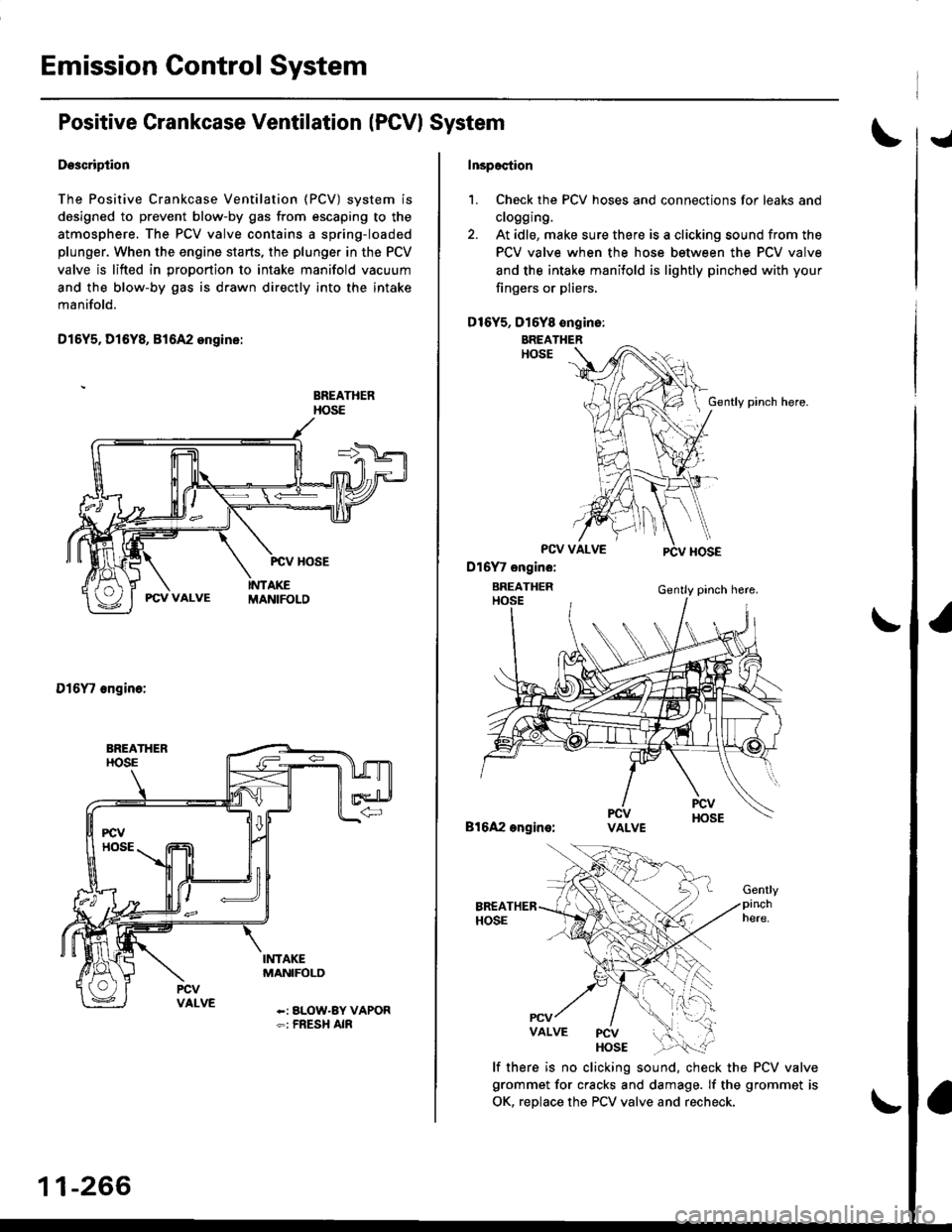
Positive Crankcase Ventilation IPCVI System
Descripiion
The Positive Crankcase Ventilation (PCV) system is
designed to prevent blow-by gas from escaping to the
atmosphere. The PCV valve contains a spring-loaded
plunger. When the engine starts, the plunger in the PCV
valve is lifted in proportion to intake manifold vacuum
and the blow-by gas is drawn directly into the intake
manifold.
D15Y5, D16Y8, 816A2 ongins:
BREATHERHOSE
Dl6'|11 6ngin6:
-: aLOW-BY VAPOR-: FnESH AIF
11-266
tJ
lrcpection
1. Check the PCV hoses and connections for leaks and
clogging.
2. At idle, make sure there is a clicking sound from the
PCV valve when the hose between the PCV valve
and the intake manifold is lightly pinched with your
fingers or pliers,
D16Y5, D16Y8 ongins:
BREATHERHOSE
PCV VALVE
Gently pinch here.
Bl6A2 engins:VALVE
lf there is no clicking sound, check the PCV valve
grommet for cracks and damage. If the grommet is
OK, replace the PCV valve and recheck.
PCV
Page 552 of 2189
\
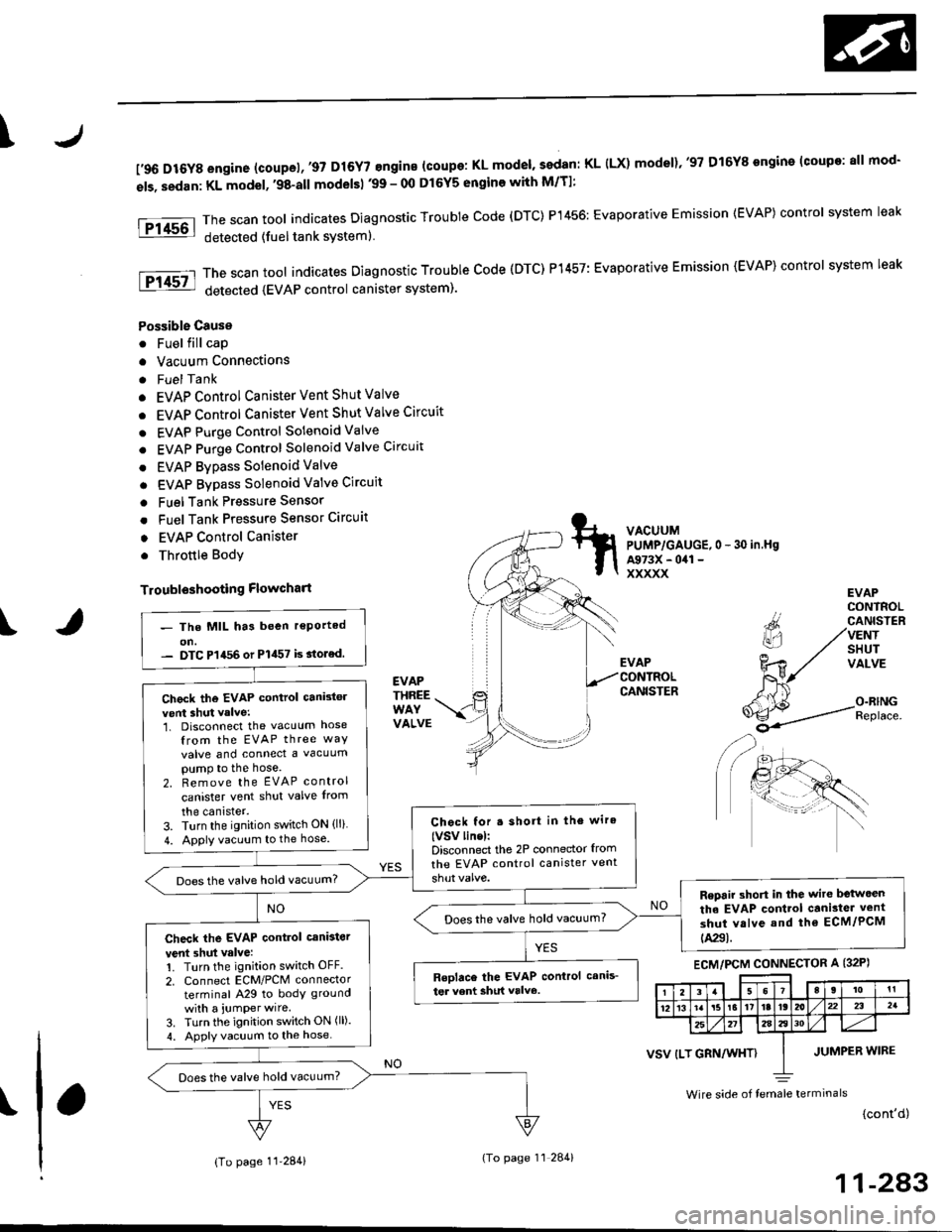
t,96 D16Y8 engine (coup6l,'9? Dl6Y7 engine (coupe: KL model, sedan: KL (LX) model)"g7 Dl6Y8 ongine (coupe: all mod-
els, sedan: KL model,'98-8ll modelsl 39 - 00 Dl5Y5 engine with M/Tl:
The scan tool indicates Diagnostic Trouble code (DTc) P1456: Evaporative Emission (EVAP) control system leak
detected (fuel tank sYsteml
The scan tool indicates Diagnostic Trouble Code (DTC) P1457: Evaporative Emission (EVAP) control system leak
detected (EVAP control canister system).
Fr4t6l
fF14s7
Possible Causs
. Fuel fill cap
. Vacuum Connections
. Fuel Tank
. EVAP Control Canister Vent Shut Valve
. EVAP Control Canister Vent Shut Valve Circuit
. EVAP Purge Control Solenoid Valve
. EVAP Purge Control Solenoid Valve Circuit
. EVAP Bypass Solenoid Valve
. EVAP Bypass Solenoid Valve Circuit
. Fuel Tank Pressure Sensor
. Fuel Tank Pressure Sensor Circuit
. EVAP Control Canister
. Throttle Body
Troublsshooting Flowchart
VACUUMPUMP/GAUGE,0 - 30 in.HgA973X - 041 -
xxxxx
I
EVAPCONTROL
.4, cANrsrER
re ./ VALVE
{S----r*::n
\(cont'd)
- The MIL ha3 been rePofted
on.- DTC P1456 or P1457 is stored.
Check the EVAP control canbtol
vent shut valve:1. Disconnect the vacuum hose
Irom the EVAP three waY
valve and connect a vacuurnpump to the hose.
2. Remove the EVAP control
canister vent shut valve Irofi
the canrster.3. Turn the ignition switch ON (lli
4. Apply vacuum to the hose.
Chock for . shon in the wire(VSv linel:Disconnect the 2P connector {rom
the EVAP control canister vent
Does the valve hold vacuum?
Repair short in the wir€ betwcen
the EVAP control canister vent
shut v.lve and tho ECM/PCM
tA29|.
Does the valve hold vacuum?
Check the EVAP control canister
vent shui valve:1. Turn the ignition switch OFF.
2. Connect ECM/PCM connectorterminal A29 to body ground
with a iumPer wire.
3. Turn the ignition switch ON (ll).
4. Applyvacuum to the hose
Reohce the EVAP control canis-
ter vent shttt valve.
Does the valve hold vacuum?
ECM/PCM CONNECTOR A {32P)
37I9t01t't2t3t5t6ItItt9202a2a
25aA
ILT GRN/W{T) I JUMPER WIRE
Wire side of femll terminals
(To page 11-284i(To page 11 284)
11-283
Page 557 of 2189
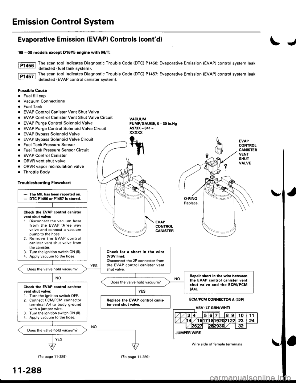
Emission Control System
Evaporative Emission {EVAP) Controls (cont'dl
\J
tF1456-l
tP14sz-l
EVAPCONTROLCANISTERVENTSHUTVALVE
O.RINGReplace.
EVAPCONTROLCANISTER
ECM/PCM CONNECTOR A I32PI
(To page 11'289)
'99 - 00 modols except Dl6Y5 engine with M/T:
The scan tool indicates Diagnostic Trouble Code (DTC) P1456: Evaporative Emission (EVAP) control system leak
detected (fuel tank svstem).
The scan tool indicates Diagnostic Trouble Code (DTC) P1457: Evaporative Emission (EVAP) control system leak
detected (EVAP control canister system).
Possible Cause
. Fuel fill cap
. Vacuum Connections
. FuelTank
. EVAP Control Canister Vent Shut Valve
. EVAP Control Canister Vent Shut Valve Circuit
. EVAP Purge Control Solenoid Valve
o EVAP Purge Control Solenoid Valve Circuit
. EVAP Bypass Solenoid Valve
0 -30 in,Hg
. EVAP Bypass Solenoid Valve Circuit
. Fuel Tank Pressure Sensor
. Fuel Tank Pressure Sensor Circuir
. EVAP Control Canister
. ORVR vent shut valve
. ORVR vapor recirculation valve
. Throttle Body
Troubleshooting Flowchart
VACUUMPUMP/GAUGE,A973X - oal -
xxxxx
T-t
t\
The MIL has been reported on.DTC P1456 o. P1457 is stored.
Check the EVAP cont.ol canistervent shul valve:1. Disconnect the vacuum hosefrom the EVAP three wayvalve and connect a vacuumpump to the hose.2. Remove the EVAP controlcanister vent shut valve fromtne canrster.3. Turn the ignition switch ON (ll).
4. Apply vacuum to the hose.Check for a short in the wiro(VSV linel:Disconnect the 2P connector fromthe EVAP control canister ventDoes the vaive hold vacuum?
RoDair 3hort in the wire botwe€nthe EVAP control canilter ventshut valve and the ECM/PCM{A4t.
Does the valve hold vacuum?Check the EVAP cont.ol canisterv€nl shut valve:1. Turn the ignition switch OFF.2. Connect ECM/PCM connectorterminal A4 to body groundwith a jumper wire.3. Turn the ignition switch ON (ll).
4. Apply vacuum to the hose.
Reolace the EVAP control canis-ter veni shut valve.
Does the valve hold vacuum?
Wire side of female terminals
11-288
lTo page 11-289)
Page 679 of 2189

Automatic Transmission
Special Tools ......... .....'."".'-.-.' 14'2
Description .,....................-...... 14-3
power Flow ......,................. 14"6
Elestronic Control System .... . ................'..'.'.. 14-13
Hvdraulic Control .....'......" 1'l-19
Hydraulic F|ow...... .'.'.".'....11-21
Lock-up System '............ ... t/t'33
Electrical System
Component Locations....,.............'......'.............'.,. 14'39
PCM Circuit Diagram
lA/T Control Syst€m: '96 - 98 Models) .........'.. 1/t-40
PCM Tarminal Volt8ge/Measuring Condhions
{'96 - 98 ModeblA/T Control System ............
PCM Circuit Disgram(A/T Conlrol System: '99 - 00 Modsls) '..........' 14-44
PCM Terminal Voltage/Measuring Conditions('99 - 00 Models)A/T Control System ...
Troubleshooting Proceduros ....
Symptom-to-ComPonent Chari
Efectricaf SFiem - '96 - 98 Models '..-.-..."'.'..11-52
Eloqtrical System -'99 - 00 Modols ... .........". 1+54
EleclricatTroubl$hooting ('96 - 98 Models)
Valve Body
Repair .................... ........'.... 14-139
Valve
Assembly
ATF Pump
1,1-1i10
Inspection ...........'.......... 14-141
Main Valvs Body
Disass€mbf y/lnspoction/R.sssembly .'.'.'.'.. -. -. 1 1-1 12
Secondsry Valve BodY
Disa$embfy/lnspoction/Rsassembly ......'.'.'.'. 11-111
Regulator Valve Body
Disa$embly/lnspoction/Rea3sembly ..........'... 14-1{5
Servo Body
Disassombly/lnsp€ction/Reassembly .".'........ 14-146
Lock-up Valv6 Body
Dis$s.mbf y/ln3poction/Rea$embly .'.. -. -..'.'.' 1 1-1 17
Mainsh!ft
Dkassembly/lnep€ction Reassembly ..'...'........ 14'148
Inspoction .............'..........'. l it-149
Countsrshaft
Disa$embly/lnspeqtion/Rea3sembly .......'...'.. 1a-l51
Dba$ombly/Re$s.mblY11-152
til-46
I rl-48
Troubleshooting Flowcharts
Electrical Troubleshooting ('9!t - 00 Models)
Troublsshooting Flowchart3
Lock-up Control Solenoid vslvo A/B AssemblY
RePlacoment
Shift Cont.ol Solenoid Valve A/B A3sembly
Inspestion
Ona-way Clutch
Disassembh/lrupoction/Rca$embly .. "'........ l4-155
Clutch
lllustlttcd Ind.x {A48A, B4RA Transmlssion) ..' 14-156
tustr.tod Index (MrnA Transmi$ionl ............ til-158
...................... 14-153
L
14-56
1+81'
14-105
1+105
Replacoment ......
Mainshaft/Countorshaft Spo€d Sonsors
Replacemsnt ......'."'........... lit'108
Hydraulic System
Symptom-to-Componeni Chart
Hydraulic Sydemr+109
t4-113
1+116
11-117
Rea$emblY
14-106 Difforrr ial
llhdraied Index........ t4-156
B.ckhrh ln3poction. 14-167
Boaring Roplacemont..-..........11-167
..... 14-108 Diftrrsniial Carrior Repl8cemeni .'.-.............'...' lil-168
Oil Sall Romovalt4-t 59
Oil Soal ln3tallstion/Sidc Clearance'......'.....'... 1'l'169
Torqua Convertcr Housing Boarings
Mlin3haft Besring/Oil Scal Roplac.ment ."..'.. lil-172
Counio6hatt Betring R.plscem.nt ..'...... ....... 14-173
Test.....,......14-106
14-107
14-160
11-162
11-171
11-175
Replacement
Test .....,.,..........
Road Te3t
Linear Solenoid AsssmblY
Stall Speed
lllustrated Indax
Transmission/End Cover'. ....
Transmission Hou3ing,.............'.'......'....""..-.-.. 11-128
Torque Conve.ter Housing/Valvo Body ........... 14-130
End Cover
14-itB Park Stop
1+119 In3pection/Adiustmsnt...'......'.'............'...."""'14-175
Transmbgion
Reassombly
11-122 Torquo Convertet/Drivr Plsie ............'.'............'.. . l4-182
Transmission
11.726 Inrtallation
Tranlmission Housing Boarings
Msinsh.ft /CounteEhaft Bearings
B!pltcomgnt
Rcvo.3s ldlor Gear
lnrtallation
Cooler Flushing ..
Shift Cabls
Test
Fluid Level
Checkin9 .........."..'.'.....
Changing
Pressure Testing
Transmission
Transmission
Rgmoval ..
lil-176
.'..........'.'.'..... 1'l-183
.... lil-187
11-132Adiustmont
RemovaUlnttallation1,1-190
lit-191Transmisgion Housing
Removal ... '.'...... ......'..... 14-l3il
Tolque Convgrter Housing/valvs Body
Rsmoval .........,...... ............. 14-136
Valve CaDs
Description .......'................. t 4'138
Shift lndicator Panel
Adiu3tmant ..'.................. 14-192
ATF Coolor Hoses
Connection ..,............,.,....... l'l-192
Shift Lever .,........