Pgm fi HONDA CIVIC 1996 6.G Workshop Manual
[x] Cancel search | Manufacturer: HONDA, Model Year: 1996, Model line: CIVIC, Model: HONDA CIVIC 1996 6.GPages: 2189, PDF Size: 69.39 MB
Page 270 of 2189

!
Fuel and Emrsslons
SoecialToofs .....,...."..,. 11-2
Component Locations
lndex ....................., ......... 11-3
Svstem Description
Vacuum Connections ................,,..,.. ......... 11-12
Electrical Connections ...............,.,.,... ....... 11-29
System Connectors ........,.,.,.......................... 1 1-51
Troubleshooting
Troubleshooting Procedures ................. .. 11-81
Engine Control Module/PowertrainControl Module TerminalAfiangement ....,.,..... 11-88
Diagnostic Trouble Code Chart .................,., 11.97
How to Read Flowcharts .,.......................... . 11-103
PGM-Fl System
System Description ...... 11-10,1
Troubleshooting Flowcharts
Engine Control Module/PowertrainContlol Module ........ 11-107
Manitold Absolute Pressure Sensor .....'. . ... 11-115
fntake Air Temperatuie Sensor ..... . . ., . 11'121
Engine Coolant Temperatuae Sensol ........., 11-128
Throttle Position Sensor ...................,........... 11-132
Primary Heated Orygen Sensor (Sensor 1l ... 11-139
Secondary Heated Oxygen Sensor(Sensor 21.................................................... 1 1-153
Heated Oxygen Sensor Heater ...................,. 11-157
Fuel Supply System ...... 11-164
Random Mislire ......., ..11-166
Misfire Detected in One Cylindsr ................. 11-167
Knock Sensor .,.,............ 11-170
CKP/TDC/CYP Sensor ................................... 11'172
Vehicle Speed Sensor ...........,......,...,.,........... 1t-176
Barometric Pressure Sensor ...............,......... I 1-178
Electrical Load Detector,.,,............................ 1 1-179
CKF Sensor .................... 11-183
ECM/PCM Internal Circuit ............................. I 1-188
A/T Signal {TMA/TMBI .................................. I 1-189
ldle Control System
System Doscriplion ............ 11-190
Troubleshooting Flowcharts
ldle Control System ...... 11-192
ldle Air Control Va1ve .................................... I 1-19i1
Starter Switch Signal .................................... 1 1'202
Air Conditioning Signal ................................. 11'201
Ahernator FR Signal .................................... . 1 1-208
BrakeSwitch Signal ..................................... f 1"210
Power Sleering Prossure Switch Signal ......11-212
A/T Gear Position Signal ............................... 11-216
Clutch Swiich Signal ................................-.... 11-214
ldte Speed Setting . .............11-220
Fuel Supply System
Fuel Lines .,...................,.,.,.,11-221
Fuef Tube/Ouick-Connect Fittings ..........,.,........ 11 -227
System Description ....'.... 11-230
Fuel Pressure .......,.,,........... 11-230
Fuef fniectors ......................11-232
Fu€f Pressure Regulator .....,.......................'...,. 11-231
Fuef Fifter ............................11-235
Fuel Pump .............'.......'.... 11-236
PGM-FI Main Relay .............11'237
Fuel Tank ................ ....,...'.'.' 11'211
Intake Air System
System Description ....-.-.....11-243
Air Cfeaner ...........,......."". .11-211
Throttle Cable .....................11-211
Throttfe Body ........ ..'... . . .,.11-211
Fuel Iniestion Air Control System ,.,.,....-........... 11-250
Emission Control System
System Description .-..........11-252
Taifpip€ Emission ...............11-252
Three Way Catafytic Convert€r ............,.,,.,.,.,.... 11 -252
Exhaust Gas Racirculaiion System ...,.,,,,.,.,.,.,,. 11'254
Positive Crankcas€ Ventilation System .... . . .. 11-266
Evaoorative Emission Controls ..................,,..,.,. 11 -267
Page 276 of 2189
I
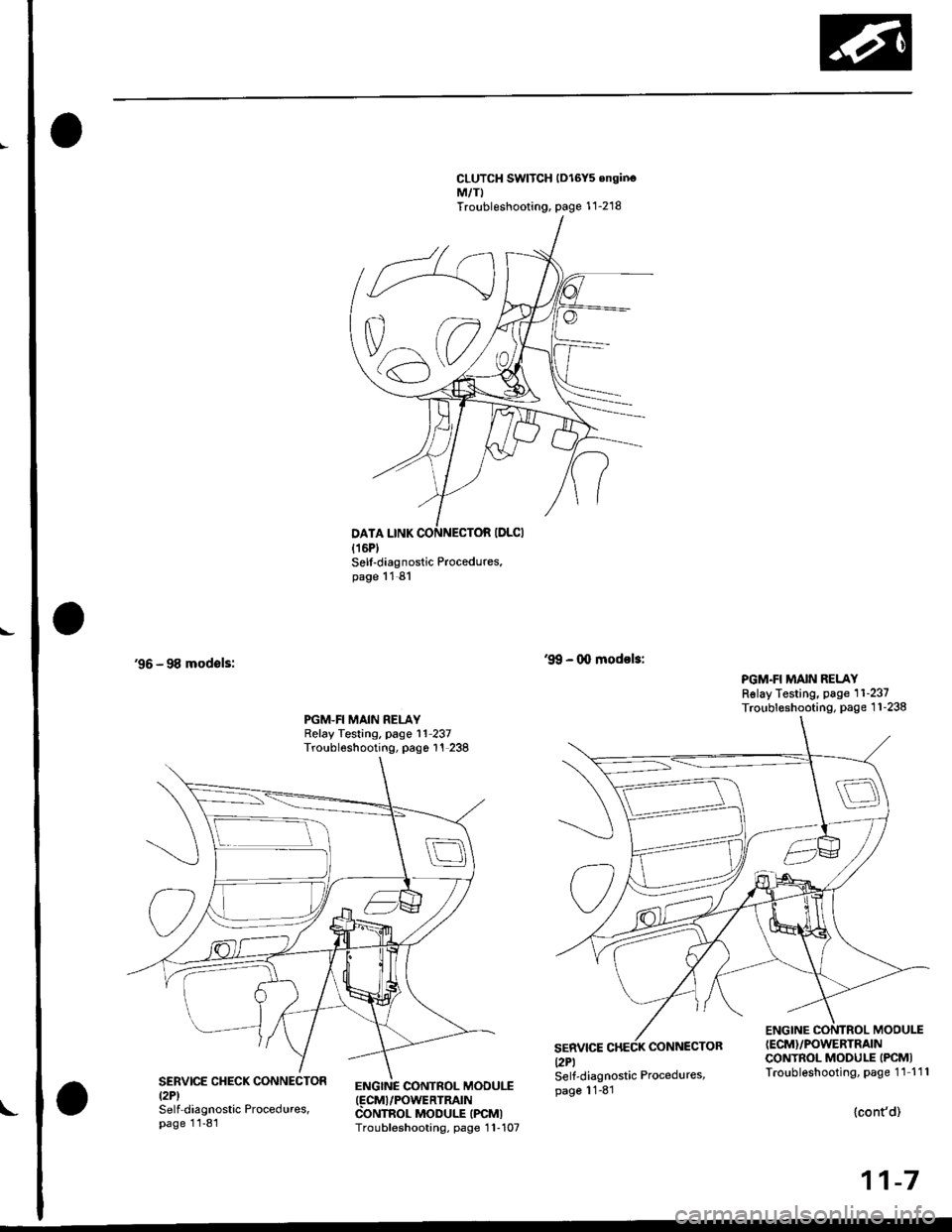
CLUTCH SWITCH lDl6Y5 onginoM,/TITroubleshooting, page 1 1-218
'96 - 98 modsls:
Sell-diagnostic Procedures.page 11 81
ENGINC CONTROL MOOUI.T(FCMI/POWERTRATN
CONTROL MODULE IPCMITroubleshooting, page 1 1-107
'9!, - 0o modol3:
PGM.FI MAIN RELAYRslay Testing, page 11-237Troubleshooting, page 1 1-238PGM.FI MAIN RELAYRelay Testing, page l1 237Troubleshooting, pago 1'! 238
SERVICEl2Pl
CONNECTOR
ENGINE CONTROL MODU1T(ECM}/POWERTRAIN
CONTROL MODULE IPCMITroubleshooting, page 11 111SERVICE CHECK CONNECTORtzPlSelf-diagnostic Procedures,page 11-81
Self-diagnostic Procedures,page 11-81
{cont'd)
11-7
Page 350 of 2189
Troubleshooting
Troubleshooting Procedures
How To Begin Troubleshooting
When the Malfunction Indicator Lamp (MlL) has been reported on, or there is a driveability problem, use the appropr'-
ate orocedure below to diagnose and repair the problem'
A. When the MIL has come on:
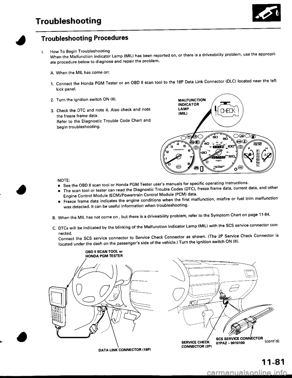
,1. connect the Honda PGM Tester or an oBD ll scan tool to the 16P Data Link connector (DLC) located near the left
kick panel.
2. Turn the ignition switch ON (ll)
3. Check the DTC and note it. Also check and note
the freeze trame data
Refer to the Diagnostic Trouble Code Chart and
begin troubleshooting.
NOTE:
.SeetheoBD||scantoolorHondaPGMTesteruser,smanua|sforspecificoperatinginstructions..
.Thescantoo|oltestercanreadtheDiagnosticTroub|ecodes(DTc},freezeframedata,currentdata,andother
Engine Control Module (ECM)/Powertrain Control Module (PCM) data'
oFreezeframedataindicatestheengineconditionswhenthefirstma|function,misfireorfue|trimma|function
was detected. lt can be useful information when troubleshooting'
B. When the MIL has not come on , out there is a d riveability problem, refer to the Symptom Chart on page 1 1-84'
c.DTcswi|lbeindicatedbytheb|inkingoftheMa|function|ndicatorLamp(M|L)withthescsserviceconnectorcon.
nected.
Connect the SCS service connector to Service Check Connector as shown (The 2P Service Check Connector is
|ocatedunderthedashonthepassenger,ssideofthevehic|e')TurntheignitionswitchoN{||)'
OBO ll SCAN TOOL olHONOA PGM TESTER
SERVICE CHECKCONNECTOR I2P)
scs sERvlcE(cont'd)
MALFUNCTIONINDICATORLAMP
DATA LINK CONNECTOR Il6PI
07PAZ - (x)l0100
11-81
Page 351 of 2189
Troubleshooting
Troubleshooting Procedures (cont,dl
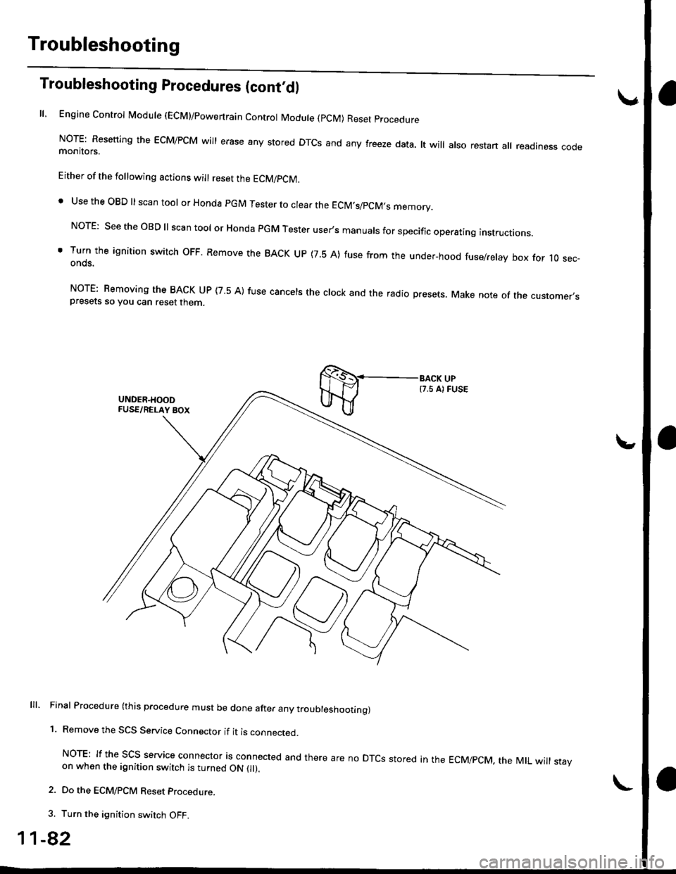
ll, Engine Control Module (ECM)/powertrain Control Module (pCM) Reset procedure
NoTE: Resetting the EcM/PcM will erase any stored DTcs and any freeze data. lt will also restart all readiness codemonitors.
Either of the following actions will reset the ECM/PCM.
. Use the OBD ll scan tool or Honda pGM Tester to clear the EClM,s/pCM,s memory.
NorE: see the oBD ll scan tool or Honda PGM Tester user's manuals for specific operating instructions.
' Turn the ignition switch oFF. Remove the BACK uP (7.5 A) fuse from the under-hood fuse/relay box for 10 sec-onds.
NorE: Bemoving the BACK uP (7 5 A) fuse cancels the clock and the radio presets. Make note of the customer,spresets so you can reset then
lll. Final Procedure (this procedure must be done after any troubleshoottng)
1. Remove the SCS Service Connector if it is connected.
NoTE: If the Scs service connector is connected and there are no DTcs stored in the EcMipcM, the MtL will stayon when the ignition switch is turned ON 0l).
2. Do the ECM/PCM Reset procedure.
3. Turn the ignition switch OFF.
1-82
Page 354 of 2189
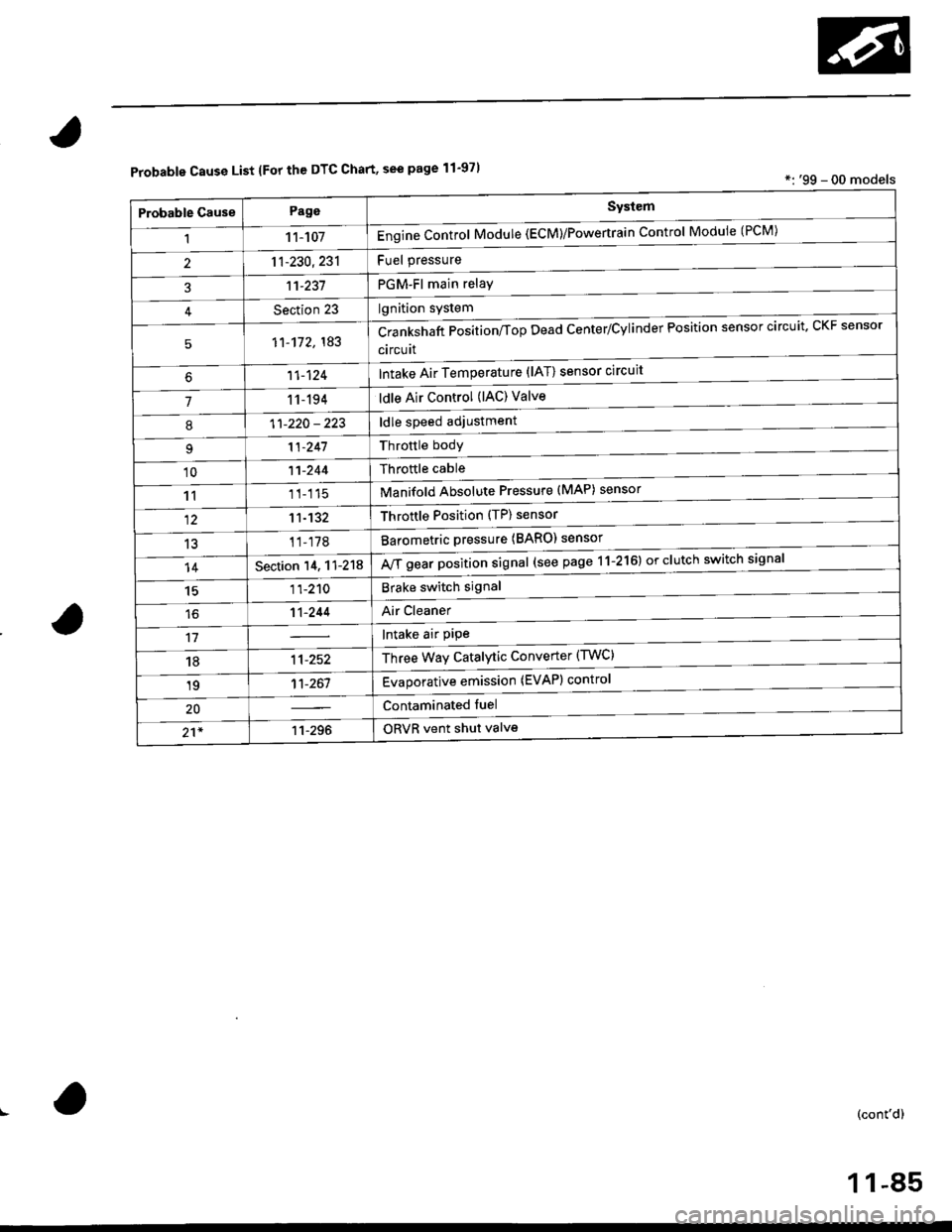
Probable Cause List lFor th€ DTC Chart, see page 11-971*: '99 - 00 models
Probable GausePageSystem
11 1-107Engine Control Module (ECM)/Powertrain Control Module (l'uM)
PGM-Fl main relay
l^^iti^n cwetam
211-230,231
3't't-237
Section 23
51'�1-172,183Crankshaft Position/fop Dead Center/Cylinder Fosltlon sensor clrculr'� Lr\F selrsor
circuit
Intake Air Temperature (lAT) sensor circuit
ldle Air Control (lAC) Valve
ldle speed adjustment
Throttle bodY
Throftle cable
Manifold Absolute Pressure (MAP) sensor
Throftle Position (TP) sensor
Barometric pressure (BARO) senso'
Mf g"a, po"ition signal (see page 11-216) or clutch switch signal
Brake switch signal
Air Cleaner
lntake air pipe
Three Way Catalytic Converter (TWC)
Evaporative emission (EVAP) control
Contaminated fuel
ORVR vent shut valvs
't1-124
71 1-194
I11-220 - 223
11-241
'1011-244
1111-115
1211-132
13't1-178
14Section 14. 11-218
1511-210
16't1-244
1811-252
1911-261
20
21*11-296
(cont'd)
11-85
Page 355 of 2189
Troubleshooting
Troubleshooting Procedures (cont,dl
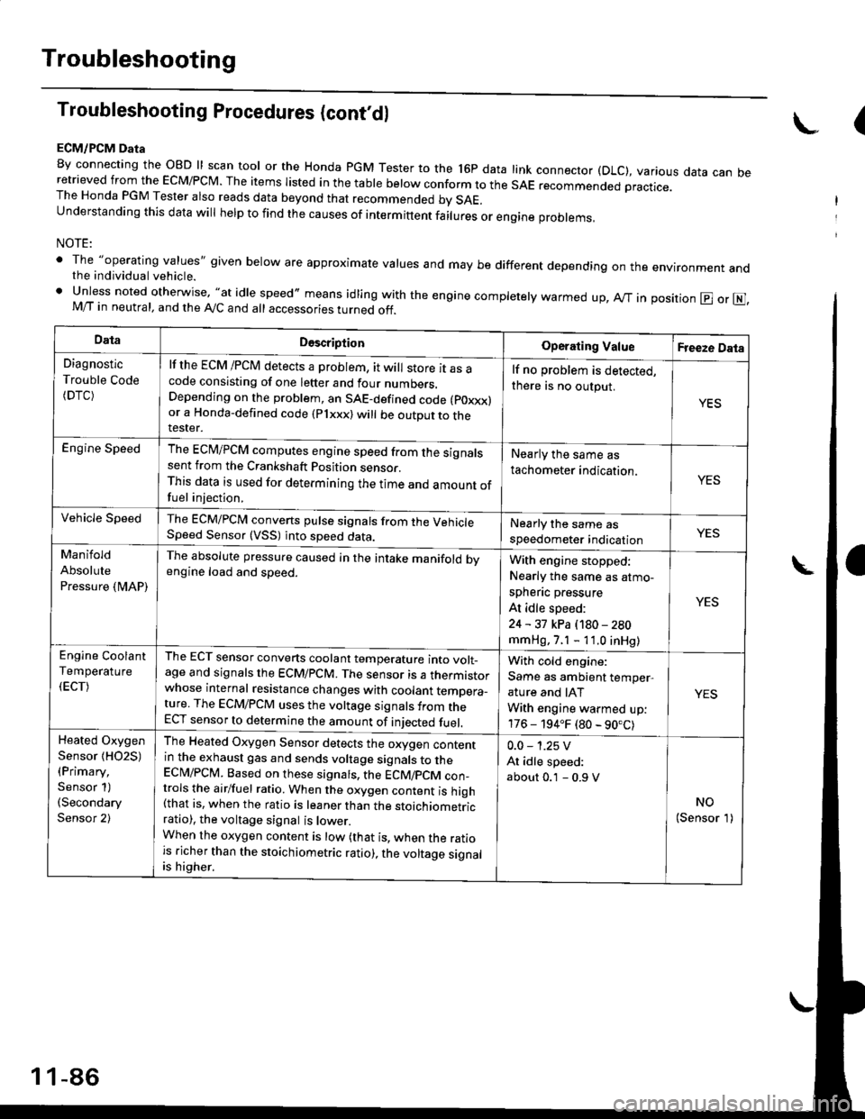
ECM/PCM Data
By connecting the OBD ll scan tool or the Honda pGM Tester to the l6p data link connector (DLC), various data can beretrieved from the EcM/PcM. The items Iisted in the table below conform to the sAE recommended practice.The Honda PGM Tester also reads data beyond that recommended bv SAE.understanding this data wil help to find the causes of intermittent fairures or engine probrems,
NOTE:
' The "operating values" given below are approximate values and may be different depending on the environment andthe individual vehicle.. Unless noted otherwise, "at idle speed,, means idling with the engine completely warmed up, Ay'T in position @ or E],M/T in neutral, and the Ay'C and all accessories turned off.
(
DataDescriptionOperating ValueFreeze Data
Diagnostic
Trouble Code(DTC)
lf the ECM /PCM detects a problem, it will store it as acode consisting of one letter and four numbers.Depending on the problem, an SAE-defined code (poxxx)or a Honda-defined code (Plxxx) will be outDut to therester.
lf no problem is detected,
there is no output.
YES
Engine SpeedThe ECM/PCM computes engine speed from the signalssent from the Crankshaft Position sensor.This data is used for determining the time and amount offuel injection,
Nearly the same as
tachometer indication.YES
Vehicle SpeedThe ECM/PCM converts pulse signals from the VehicleSpeed Sensor (VSS) into speed data.Nearly the same as
speedometer indicationYES
Manifold
Absolute
Pressure {MAP)
The absolute pressure caused in the intake manifold bvengine load and speed.With engine stopped:
Nearly the same as atmo-
spheflc pressure
At idle speed:
24 - 31 kPa (180 - 280
mmHg, 7.1 - 11.0 inHg)
YES
Engine Coolant
Temperature
(ECT)
The ECT sensor converts coolant temperature into volt_age and signals the ECM/PCM. The sensor is a thermistorwhose internal resistance changes with coolant temDera_ture. The ECM/PCM uses the voltage signals from theECT sensor to determine the amount of iniected fuel.
With cold engine:
Same as ambient temper,
ature and IAT
With engine warmed up:
176 - 194.F (80 - 90.C)
YES
Heated Oxygen
Sensor {HO2S)(Primary,
Sensor 1)(Secondary
Sensor 2)
The Heated Oxygen Sensor detects the oxygen contentin the exhaust gas and sends voltage signals to theECI\4/PCM. Based on these signats, the ECM/pCM con_trols the airlfuel ratio. When the oxygen content is high(that is, when the ratio is leaner than the stoichiometricratio), the voltage signal is lower.When the oxygen content is low (that is, when the ratiois richer than the stoichiometric ratio), the voltage signalis higher.
0.0 - 1.25 V
At idle speed:
about 0.1 - 0.9 V
NO(Sensor 1)
1 1-86
Page 373 of 2189
PGM-FI System
System Description
CKP/TDC/CYP Sensor
MAP Sensor
IAT SensorTP SensorEGR Valve Lift Sensor*'Primary H02SSecondary HO2SVSSBARO SensorELD*'KS€Starter SignalALT FR SignalAir Conditioning SignalA/T Gear Position SignalBattery Voltage {lGN.1}Erake Switch SignalPSP Switch SignalFuel Tank Pressure Sensor*iVTEC Pressure Switch*5Clutch Switch Signal*6Countershaft Speed SensornBMainshaft Speed Sensorrs
-\
----t /
F;ilrr j"-----fi-tri-'r.;l
Fb"t."'i" d" c;;il
F,h"'c;;tr*".io";-l
@."r.l"sc;;ll
EaM/PcM B""k-p F"""till
r\
-:/
Fuel IniectorsPGM-Fl Main Belay {Fuel Pump)MILIAC Valve!y'C Compressor Clutch RelayRadiator Fan Relay*,Condenser Fan RelayALT*'lcMEVAP Purge Control Solenoid
Primary HO2S HeaterSecondary H02S HeaterEGR Control Solenoid Valve*rEGR valve*6EVAP Bypass Solenoid Valve*'EVAP Control Canister Vent Shut
VTEC Solenoid Valve*5DLCLock-up Control Solenoid Valve*aShift Control Solenoid Valve*3Linear Solenoid Valve*3
*1: Dl6Y5 engine*2: USA model*3: CW (D16Y5 ensine), D16Y8 engine and 81642 ensine*4: '96 D16Y8 engine lcoupe),'97 Dl6Y7 engine (coupe: KL model, sedan: KL (LX) model),'97 D16Y8 engine {coupe: all models, sedan: KLmodel),'98-all models,'99'all models,'00-all models+5: D16Y5, D16Y8,816A2 engine*6: M/T (D16Y5 enginei*7: CVT 1D'l6Y5 engine)+8: A/T (D16Y7, D16Y8 engine)*9: '96 D16Y5 engine,'96 D16Y7 engine,'96 Dl6Y8 engine (sedan),'97 D16Y5 engine,'97 Dl6Y7 engine (coupe: KA, KC models, sedan:KA, KC, KL (LX) models, hatchback: all models),'97 D16Y8 engine (sedan: KA, KC modelsi
PGM-FI Sy3lem
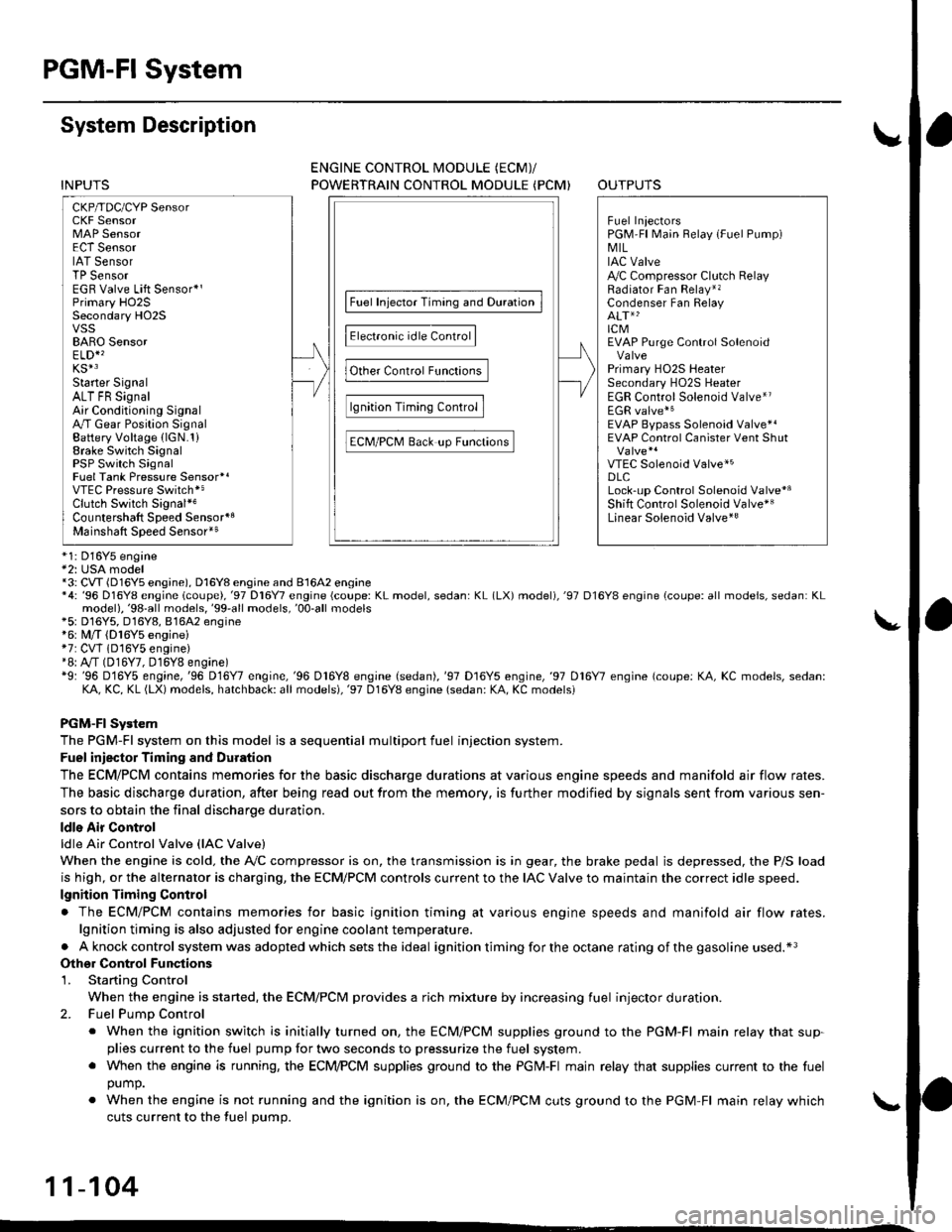
The PGM-Fl system on this model is a sequential multipon fuel injection system.
Fuel iniector Timing and Duration
The ECM/PCM contains memories for the basic discharge durations at various engine speeds and manifold air flow rates.
The basic discharge duration, after being read out from the memory. is further modified by signals sent from various sen-
sors to obtain the final discharge duration.
ldle Air Control
ldle Air Control Valve llAC Valve)
When the engine is cold. the A,/C compressor is on, the transmission is in gear, the brake pedal is depressed, the P/S load
is high, or the alternator is charging, the ECM/PCM controls current to the IAC Valve to maintain the correct idle speed.
lgnition Timing Control
. The ECM/PCM contains memories for basic ignition timing at various engine speeds and manifold air flow rates.
lgnition timing is also adjusted for engine coolant temperature.
. Aknockcontrol system was adopted which sets the ideal ignition timing for the octane rating ofthegasoline used.*3
Othgr Control Funqtions
1. Starting Control
When the engine is started, the ECM/PCM provides a rich mixture by increasing fuel injector duration.
2. Fuel Pump Control
. When the ignition switch is initially turned on, the ECM/PCM supplies ground to the PGM-Fl main relay that sup-plies current to the fuel pump for two seconds to pressurize the fuel system.. When the engine is running, the ECI\4PCM supplies ground to the PGM-FI majn relay that supplies current to the fuel
oumo.
. When the engine is not running and the ignition is on, the ECM/PCM cuts ground to the PGM-FI main relay which
cuts current to the fuel pump.
11-104
INPUTS
ENGINE CONTROL MODULE (ECMY
POWERTRAIN CONTROL MODULE (PCM) OUTPUTS
Page 375 of 2189
PGM-FI System
System Description (cont'dl
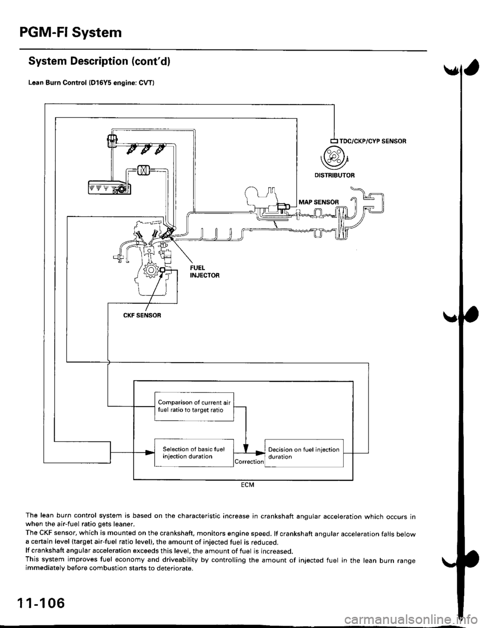
Lean Burn Control {D16Y5 engine: CvT)
The lean burn control system is based on the characteristic increase in crankshaft angular acceleration which occurs inwhen the air-fuel ratio gets leaner.
The CKF sensor, which is mounted on the crankshaft, monitors sngine speed, lf crankshaft angular acceleration falls belowa certain level (target air-fuel ratio level), the amount of injected fuel is reouceo.
lf crankshaft angular acceleration exceeds this level. the amount of fuel is increased.
This system improves fuel economy and driveability by controlling the amount of injected fuel in the lean burn rangeimmediatelv before combustion starts to deteriorate.
1 1-1 06
TOC/CKP/CYP SENSOR
MAP SENSOR
CKF SENSOR
ECM
Comparison oI current airfuel ratio to target ratio
Page 377 of 2189
PGM-FI System
Engine Control Module/Powertrain Control Module (ECM/PCMI
('96 - 98 Models,'99 - 00 Dl6Y5 engine with M/Tl (cont'd)
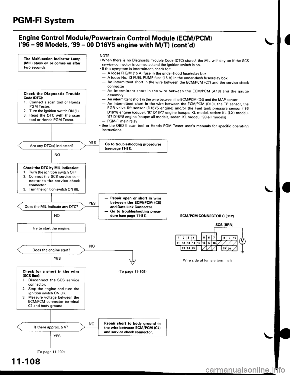
NOTE:. When there is oo Diagnostic Trouble Code (DTC) stored, the MtL wi
stay on if the SCSservace connector is connected and the ignition switch is on,. lf this symptom is intermittent, checklor:- A loose Fl E/M 115 A) fuse in the under hood luse/relay box- A loose No. 13 FUEL PUMP fuse (15 A) in the underdash fuse/relay box- An intermittent shon in the wire between the ECM/PCM (C7) and the service cnecKconnector- An intermittent short in the wire between the ECM/PCM (A18) and the gaugeassembly- An intermittent shon in the wire between the ECM/PCM {D4) and the MAp sensorAn intermittent short in the wire between the ECM/PCM (D10), the Tp sensor, theEGR valve l:ft sensor (D16Y5 engine) and/or the Fuel tank pressure sensor (,96Dl6Y8 engine (coupe), '97 016Y7 engine (coupe: KL model, sedan: KL (LX) modeli,'97 016Y8 engine {coupe: all models, sedan: KL modeti,'98,all models}- PGM-FImain relay. See the OBD ll scan tool or Honda PGM Tester user's manuals lor specitic operatinginstructions.
ECM/PCM CONNECTOR C 13lPI
Wire side of female terminals
(To page 11 109)
(To page 11,109)
11-108
The Maltunction Indicator Lamp(MlLl stays on o. comes on eftartwo s€conds,
Check the Oiagnoslic TroubleCode {DTC}I1. Connect a scan tool or HondaPGM Tester.2. Turn the ignition switch ON (ll).
3. Read the DTC with the scantool or Honda PGM Tester.
Go to troubleshooting p.oc€dur€s(se€ pago 11{11.Are any DTC{s) indicated?
Check the DTC by MIL indication:1. Turn the ignition switch OFF.2. Connect the SCS service con,nector to the service checkconnector.3. Turn the ignition switch ON (lli.
Repair opon ol short in wirebotwoen the ECM/PCM (C8)
and Data Link Connector.Go to troublelhooting proce-dure ls6e page 11-811.
Does the MIL indicate any DTC?
Try to start the engine.
Does the engine start?
Check for a short in the wire(SCS lin€l:1. Disconnect the SCS serviceconnector.2. Stop the engine and turn theignition switch ON {lli.3. Measure voltage between theECM/PCM connector terminalC7 and body ground.
Ropair short to body Iround inthe wire betweon ECM/PCM lCTland sorvice check connector.
ls there approx. 5 V?
scs tBRNI
Page 378 of 2189
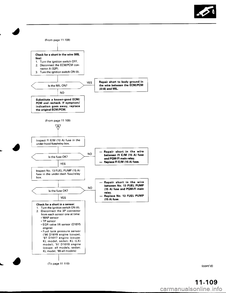
lFrom page 11 108)
Check for a short in the wire {MlLlinell1. Turn the ignition switch OFF.
2. Disconnect the Eclvl/PCM con-nector A (32P).
3. Turn the ignition switch ON {ll).
Ropair short to body gtound in
the wir. between the ECM/PCM
lA18) and MlL.ls the MIL ON?
Substitute a known-good ECM/
PCM and recheck. lt 3ymptom/indicaiion goes away, rePlace
ihe original ECM/PCM.
(From page 11 108)
Inspect Fl E/M (10 A) fuse in theundeFhood Iuse/relay box.
- Repair short in the wirg
b€tweon Fl E/M (15 A) luse
and PGM-FI main rolay.- Replace Fl E/M (15 Alfuse.
Inspect No. 13 FUEL PUMP (15 A)
fuse in the under-dash fuse/relaY
- Repait lhort in the wire
botween No. 13 FUEL PUMP
115 Al fuse and PGM-FI main
reray.- Roplace No. 13 FUEL PUMP115 Al tu3o.
Check for a short in a 3€nsor:1. Turn the ignition switch ON (lli.
2. Disconnecl the 3P connectorfrom each sensor one at time:
. TP sensor. EGR valve lift sensor (D16Y5
engrne). Fuel tank pressure sensor('96 D16Y8 engine (coupe),'97 D16Y7 engine (couPe:
KL model, sedan: KL (LX)
model),'97 D16Y8 engine
lcoupe: all models, sedan:KL model,'98-all models)
{To page 11 110)(cont'd)
1 1-109
!