thermo HONDA CIVIC 1996 6.G Workshop Manual
[x] Cancel search | Manufacturer: HONDA, Model Year: 1996, Model line: CIVIC, Model: HONDA CIVIC 1996 6.GPages: 2189, PDF Size: 69.39 MB
Page 51 of 2189
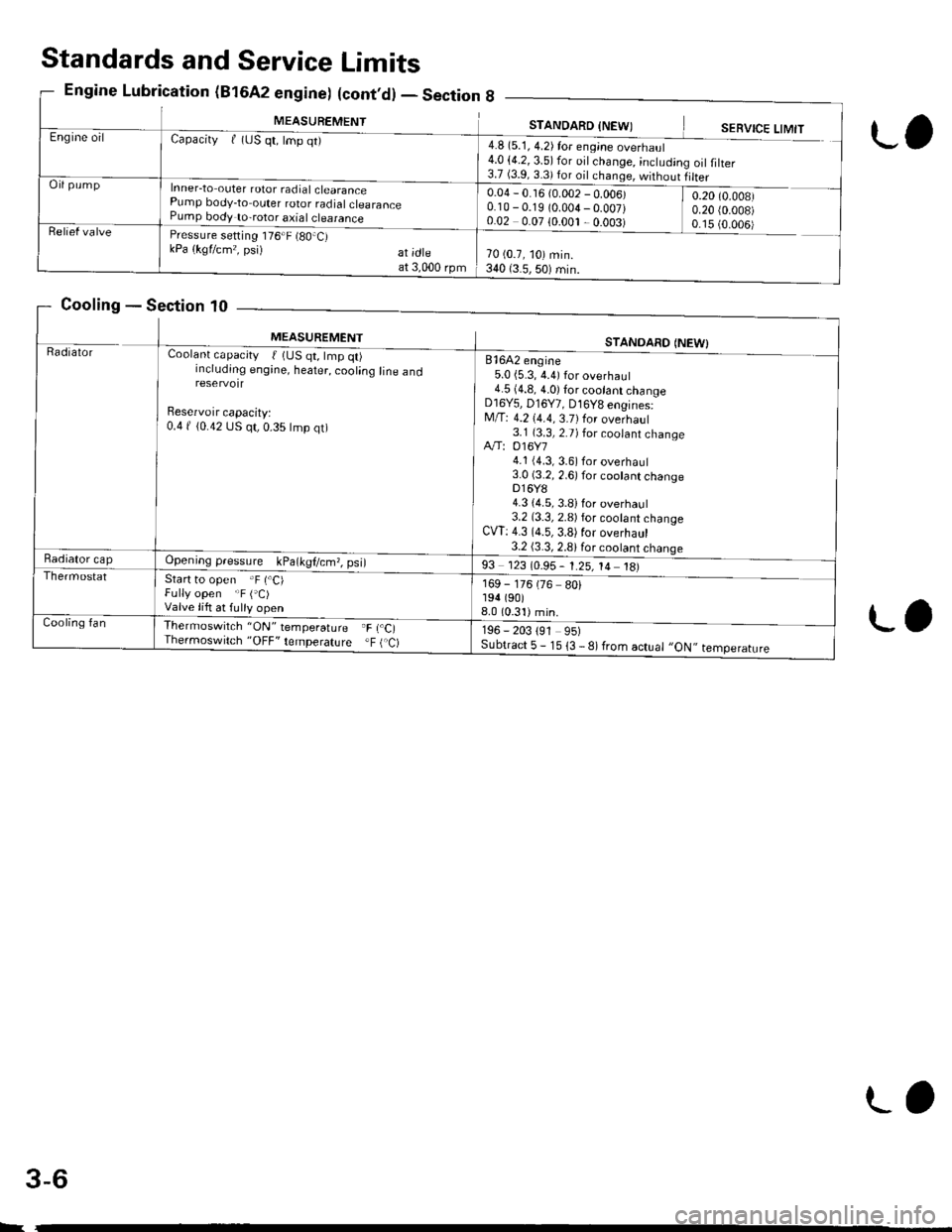
MEASUREMENTSTANDARD INFWIEngine oilCapacityf (uS qt, lmp qt)
Inner-to outer rotor radial clearancePump body-to outer rotor radialclearancePump body to-rotor axial clearance
4.8 (5.1, 4.2) for eng;ne overhaul4.0 (4.2, 3.5) for oil change, ;ncludin3.7 (3.9.3 3)for dil .h,nde '^,irh^,,rg oilfilter
Oil pump0.04 - 0.16 {0.002 - 0.006)0.10 - 0.19 (0.004-0.007)0.02 0.07 10.001 ,0.003)
0.20 (0.008)
0.20 {0.008)0 15 {O OO6iRelief valvePressure setting 176"F (80.C)kPa (kgflcm,, psi) at;dteat 3,000 rpm70 (0.7, 10) min.340 (3.5,50) min.
Standards and Service Limits
Engine Lubrication (B16A2 engine) (cont,d) - Section 8
Cooling - Section 10
L,
L.
MEASUREMENTSTANOARO {NEW)RadratorCoolant capacity t 1US qt, tmp qt)including engine, heater, cooling line andreservotr
Beservoir capacity:0.4 f {0.42 US qt, 0.35 lmp qt)
81642 engine5.0 {5.3, 4.4) for overhaul4.5 (4.8, 4.0) for cootant changeD16Y5, D16Y7, D16Y8 engines:M/T: 4.2 (4.4, 3.7)for overhaul3.1 (3.3, 2.7) for coolant changeA"/T: 016Y74.1 (4.3, 3.6) for overhaul3.0 (3.2, 2.6) for cootant changeDl6Y84.3 {4.5, 3.8)for overhaul3.2 (3.3, 2.8) for cootant changeCW: 4.3 (4.5,3.8)for overhaul3.2 (3.3, 2.8)for cootant chanqeRadiator capOpeningpressure kPa(kgl/cm,,psi)
Start to open .F (.C)Fully open "F ('C)Valve lift at fulty open
93 123 (0.95- 1.25, 14 18)
169 - 176 (76 80)194 (90)
8.0 (0.31)min.
196 - 203 191 95)Subtract 5 - 15 {3 - 8) from actual ,,ON,, temperature
Thermostat
Cooling fanThermoswilch 'ON" temperature F r.C,Thermoswitch "OFF' lemperature .F ( C)
L
3-6
L,
Page 152 of 2189
Valve Guides
7.
VALVESEAT
PFUSSIAN BTUE COMPOUNO
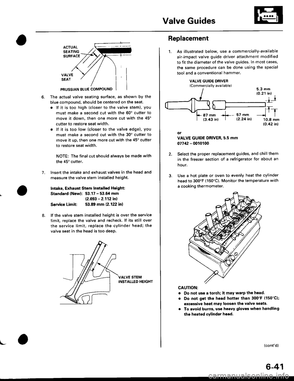
The actual valve seating surface. as shown by the
blue comDound, should be centered on the seat.
. lf it is too high (closer to the valve stem), you
must make a second cut with the 60'cutter to
move it down, then one more cut with the 45'
cutter to restore seat width,
. lf it is too low (closer to the vslve edge), you
must make a second cut with the 30" cutter to
move it uD, then one more cut with the 45'cutter
to restore seat width.
NOTE: The final cut should always be made with
the 45" cutter.
lnsert the intake and exhaust valves in the head and
measure the valve stem installed height.
Intake. Exhau3t Siem Installsd Height:
Standard (New): 53.17 - 53.6,4 mm
12.093 - 2.112 in)
Sorvice Limit: 53.89 mm (2.122 in)
lf the valve stem installed height is over the service
limit. reDlace the valve and recheck. lf its still over
the service limit, replace the cylinder head; the
valve seat in the head is too deep.
VALVE STEMINSTALLED HEIGHT
8.
\-
Replacement
1.As illustrated below, use a commercially-available
air-impact valve guide driver attachment modified
to fit the diameter of the valve guides. In most cases.
the same procedure can be done using the special
tool and a conventional hammer.
VALVE GUIDE DRIVERlCommerciallv available)5.3 mm
87 mm +- 57 mft
t3.43 in) | 12 24 inl
tr-r'10.8 mm(0.42 inl
or
VALVE GUIDE DRIVER, 5.5 mm
07742 - 0010100
Select the proper replacement guides. and chill them
in the freezer section of a refrigerator for about an
nour.
Use a hot plate or oven to evenly heat the cylinder
head to 300"F (150'C). Monitor the temperature with
a cooking thermometer.
CAUTION:
. Do not use a torch; it may warp the head.
Do not got the head hottel than 300"F (150"C1;
excessive heat may loosen thg valve seats.
To avoid burns. use heayy gloves whon handling
the heated cylinder h€ad.
{cont'd)
6-41
Page 190 of 2189
t
Valve Guides
Replacement
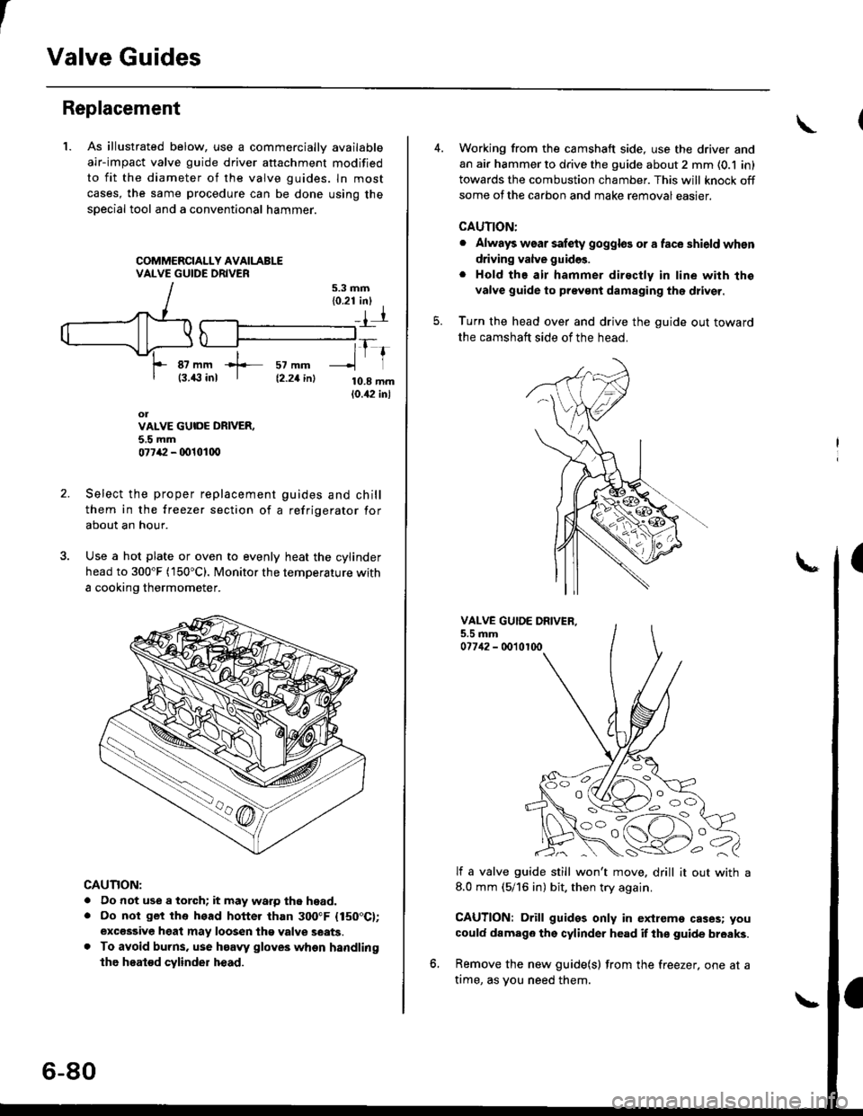
1. As illustrated below, use a commerciallv available
air-impact valve guide driver attachment modified
to fit the diameter of the valve guides. ln most
cases, the same procedure can be done using the
sDecial tool and a conventional hammer.
COMMERCIALLY AVAILABLEVALVE GUIDE DRIVER
87 mm -L- sz mm(3.43 inl I tz.zr int
rE-tt
10.8 mm10.42 inl
olVALVE GUIOE DRIVER,5.5 mm077,P - 0010100
Select the proper replacement guides and chill
them in the freezer section of a refrigerator for
about an hour.
Use a hot plate or oven to evenly heat the cylinder
head to 300"F (150"C). Monitor the temperature with
a cooking thermometer.
CAUTION:
. Do not use a torch; it may warp tho head.. Do not get tho head hotter than 300"F {150"C};excesgive heat may loosen thg valve seats.. To avoid burns. use haaw gloves whon handling
the heatod cylinder head.
6-80
Working from the camshaft side, use the driver and
an air hammer to drive the guide about 2 mm (0.1 in)
towards the combustion chamber. This will knock off
some ofthe carbon and make removaleasier.
CAUTION:
. Always wsar safety goggles or a face shield whsn
driving valve guides.
. Hold the air hammer dir€ctly in line with the
valve guide to prevont damaging thg dtiver.
Turn the head over and drive the guide out toward
the camshaft side of the head.
VALVE GUIOE DRIVER,5.5 mm077{2 - 0010100
lf a valve guide still won't move. drill it out with a8.0 mm (5/16 in) bit, then try again.
CAUTION: Drill guides only in extreme cases; you
could damago the cylinder head if ths guide br6aks.
Remove the new guide(s) from the freezer, one at a
time, as vou need them.
-:^-,65i^q
NNSp-<
Page 256 of 2189
Cooling
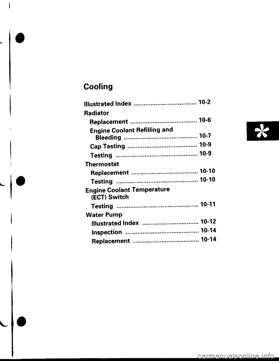
fllustrated Index ."..."... ""' 10-2
Radiator
Replacement .'....'...."..."
Engine Coolant Refilling and
Bleeding
Cap Testing
Testing
Thermostat
Replacement .............'....
Testing
10-6
10-7
10-9
10-9
10-10
10-10
Engine Goolant TemPerature
(ECT) Switch
Testing """ 10-11
Water PumP
fffustrated Index ......'... " 10-12
Inspection ' 10'14
Replacement ..'..'...."...'.'....'..'.....'.""" 10-14
!
Page 258 of 2189
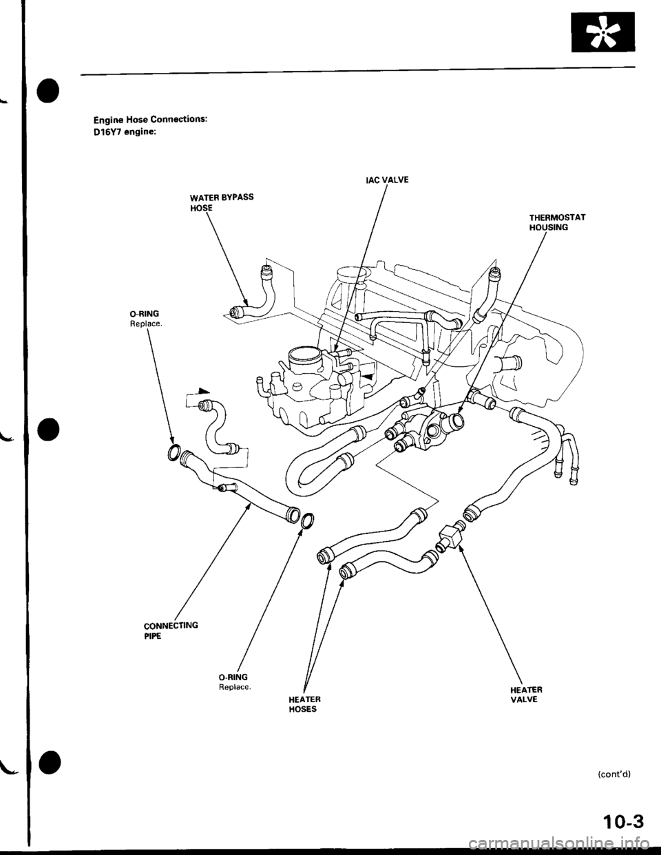
lv
Engine Hose Connections:
D15Y7 engine:
CONNECTINGPIPE
HEATERHOSES
{cont'd)
IAC VALVE
WATEF BYPASS
THERMOSTATHOUSING
VALVE
10-3
Page 259 of 2189
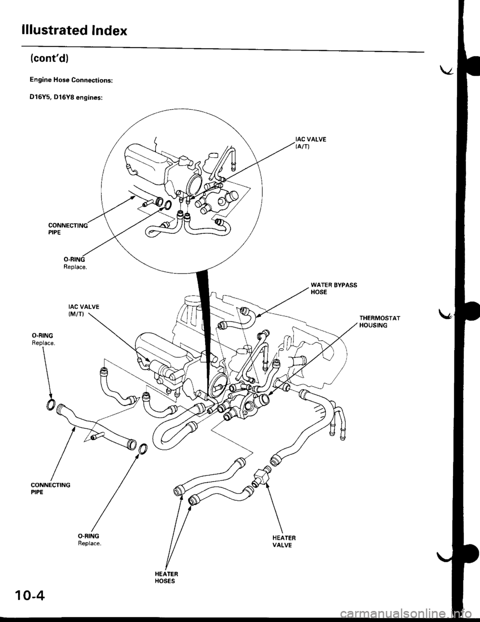
lllustrated Index
(cont'd)
Engine Hose Connections:
D16Y5, D16Y8 engines:
Replace.
IAC VALVE(M/TI
IAC VALVE{A/T)
WATER BYPASSHOSE
THERMOSTATHOUSING
O.RINGReplace.
\
\
\
\h
CONNECTINGPIPE
HEATERVALVE
HEATERHOS€S
10-4
Page 260 of 2189
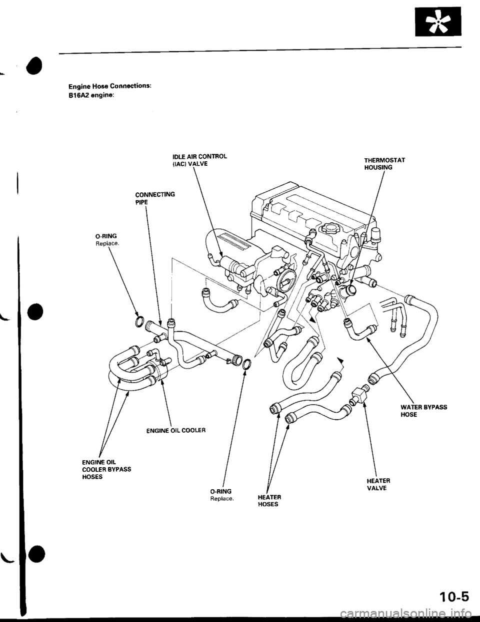
CONNECTINGPIPE
Engine Hose Conneqtions:
81642 engine:
O-RINGReplace.
b
WATER BYPASSHOSE
HEATERVALVE
HEATERHOSES
THERMOSTATHOUSING
ENGINE OIL COOLER
10-5
Page 265 of 2189
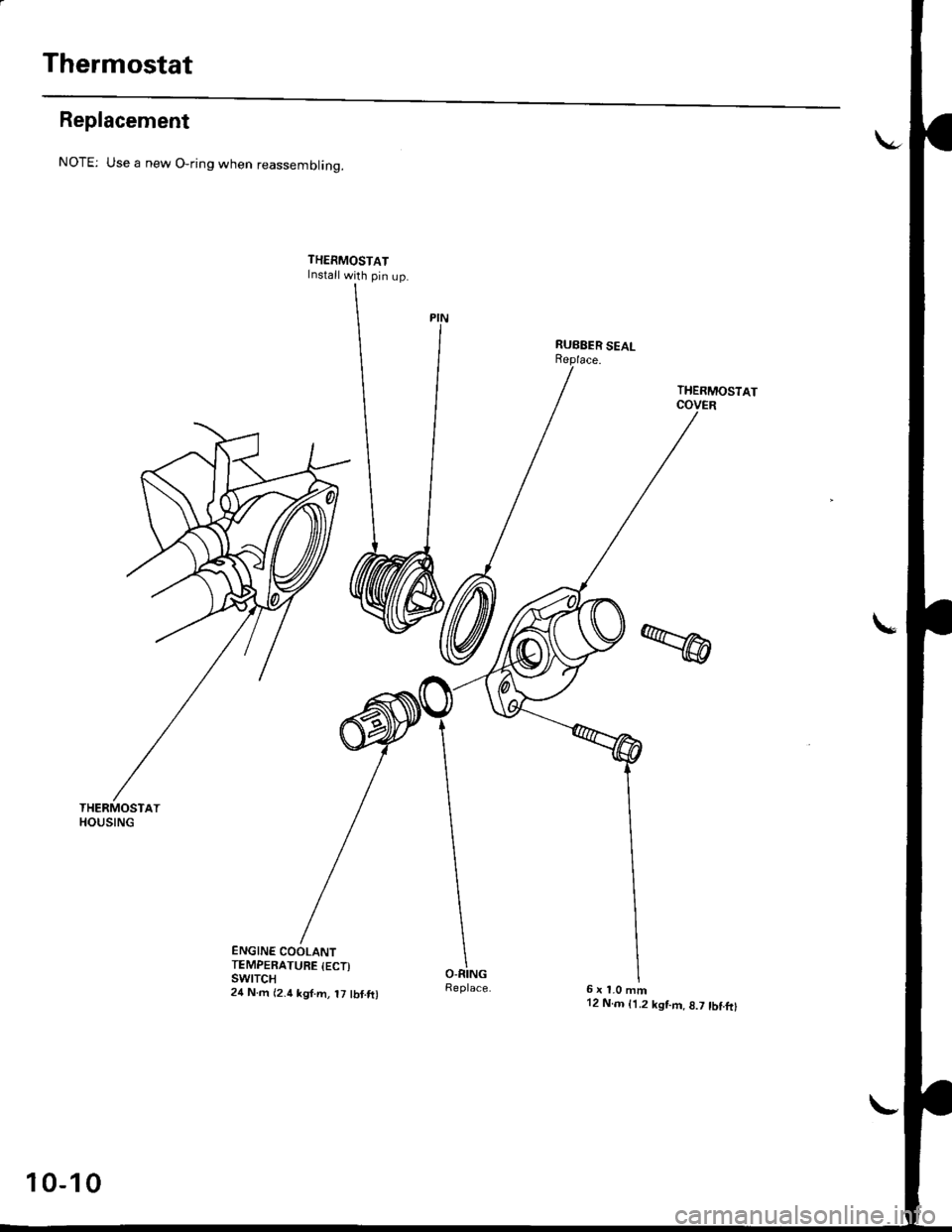
Thermostat
Replacement
THERMOSTATHOUSING
NOTE: Use a new O-ring when reassemblinq.
THERMOSTATInstall with pin up.
ENGINE COOLANTTEMPERATURE {ECT)swtTcH24 N.m {2.4 kgf.m, t7 tbf.ft)
THERMOSTAT
6x1.0mm12 N.m {1.2 kgf.m,8.7 tbf.frl
10-10
Page 266 of 2189
EGT Switch
-f
Testing
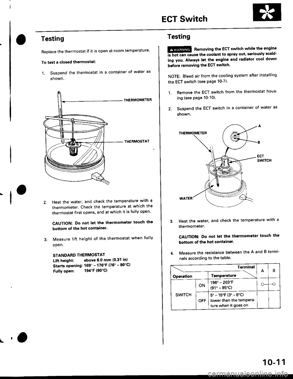
Replace the thermostat if it is open at room temperature'
To test a closed thermostat:
1, Suspend the thermostat in a container of water as
shown.
THEBMOMETER
THERMOSTAT
Heat the water, and check the temperature with a
thermometer. Check the temperature at which the
thermostat first opens, and at which it is fully open
CAUTION: Do not let the thermometer touch the
bottom of the hot Gonlainel.
Measure lift height of the thermostat when fully
open.
STANDARD THERMOSTAT
Lift height above 8.0 mm (0.31 inl
Starts opsning: 169' - 176'F (76' - 80'Cl
Fully open: 194'F {90"C1
!'o
10-1 1
Testing
!!@ Romoving the EcT swhch while lhs engine
i!-ot can cause the coolant to sPray out, seriously scald-
ing you. Always lst th€ ongine and rediator cool down
before removing ihe ECT switch.
NOTE: Bleed air from the cooling system after installing
the ECT switch (see Page 10-7)
1. Remove the ECT switch from the thermostat hous-
ing (see Page'10-10).
2. Suspend the ECT switch in a container of water as
shown.
Heat the water, and check the temperature with a
thermometer.
CAUTION: Do not let the thermomoter touch tho
bottom of the hot container'
Measure the resistance between the A and B termi-
nals according to the table.4.
Terminal
Oo"rffi
swlTcH
ON196' - 203"F
(91" - 95'C)o--o
OFF
5" - 15'F {3" - 8'C)
lower than the temPera-
ture when t goes on
Page 397 of 2189
PGM-FI System
Engine Coolant Temperature (ECTI Sensor
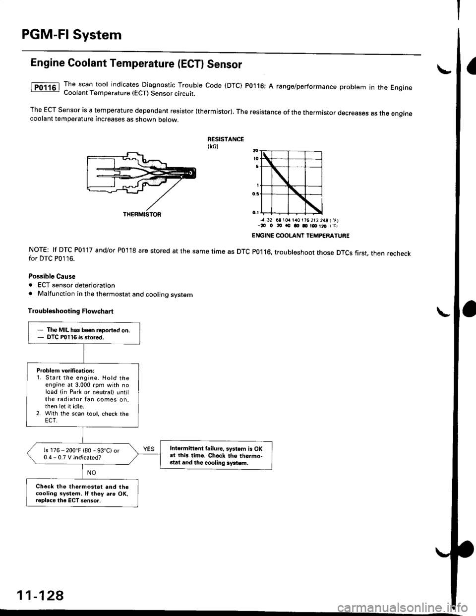
The scan tool indicates Diagnostic Trouble code (DTC) P0116; A range/performance problem in the EngrneCoolant Temperature (ECT) Sensor circuit.
The ECT Sensor is a temperature dependant resistor (thermistor). The resistance of the thermistor decreases as the enginecoolant temperature increases as shown oetow.
RESISTANCE(ko)
NOTE: lf DTC P0117 and/or P01'18 are stored at the same time as DTCfor DTC P0116.
Possible Cause
. ECT sensor deterioration. Malfunction in the thermostat and cooling system
Troubleshooting Flowchart
-a 32 68 r0a la0l?6 2t2 2481'rr-20 o 20 ao o D r@ Il, r'c)
ENGINE COOLANT IEMPERATURE
P0116, troubleshoot those DTCS first. then recheck
11-128
THERMISTOR
- The MIL has bogn reported on.- DTC P0116 is stored.
Problem verification:1. Start the engine. Hotd theengine at 3,000 rpm with noload (in Park or neutral) untilthe radiator fan comes on,then let it idle.2. With the scan tool, check the
Intermiftent lailure. system is OKai thi. time. Ch.ck the thc.mo-stat 6nd thc cooling system.
is 176 200'F {80 - 93'C)or0.0-0.TVindicated?
Check the thermostat and thecooling system. ll they als OK,raplace the ECT sensor.