Connectors HONDA CIVIC 1997 6.G Owners Manual
[x] Cancel search | Manufacturer: HONDA, Model Year: 1997, Model line: CIVIC, Model: HONDA CIVIC 1997 6.GPages: 2189, PDF Size: 69.39 MB
Page 801 of 2189
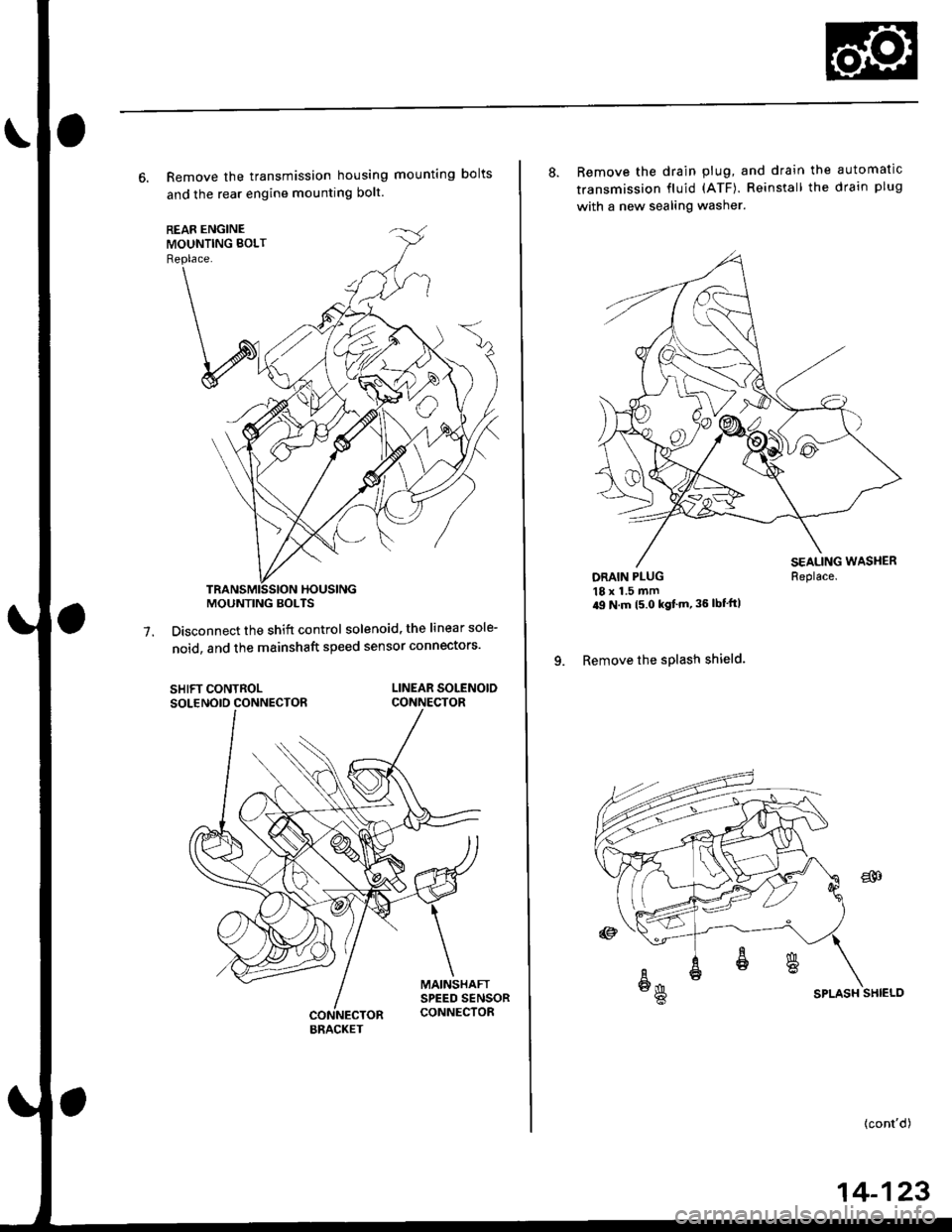
6. Remove the transmission housing mounting bolts
and the rear engine mounting bolt.
Disconnect the shift control solenoid, the linear sole-
noid, and the mainshaft speed sensor connectors'7.
SHIFT CONTROLSOLENOID CONNECTORLINEAR SOLENOIDCONNECTOR
MOUNTING BOLTS
BRACKET
8. Remove the drain plug, and drain the automatic
transmission fluid (ATF). Reinstall the drain plug
with a new sealing washer.
DRAIN PLUG18 x 1.5 mm'9 N m t5 o kgf'm' 36 lbf'ft|
9. Remove the splash shield.
Replace.
SPLASH SHIELD
{cont'd)
14-123
Page 863 of 2189
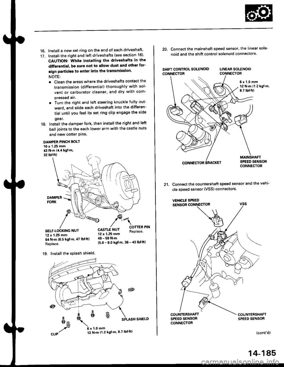
16. Install a new set ring on the end of each driveshaft'
17. Installthe right and left driveshafts (see ssction 16)
CAUTION: Whil6 installing the driveshafE in the
diffarential, be surs not lo allow du3t and othor for-
eign particl€s to enler into the transmission.
NOTE:
. Clean the areas where the driveshafts contact the
transmission (differential) thoroughly with sol-
vent or carburetor cleaner, and dry with com-
pressed air.
. Turn the right and left steering knuckle fully out-
ward, and slide each driveshaft into the differen-
tial until you feel its set ring clip engage the side
gear.
18. Install the damper fork, then install the rightand left
ball joints to the each lower arm with the castle nuts
and new cotter Plns.
DAMPER PINCH BOLT
10 x 1 .25 mma3 N.m l4.ia kgf.m,
32 tbl.ftl
4l
COTTERReplace.SELF.LOCKING NUT
12 x 1.25 mm
6il N.m t6.5 kgf'm, il7 lbf ftl
Replace.
19. Install the splash shield.
{5.0 - 6.0 kgf m, 36 - iB lbf'ft|
CASTLE NUT12 x 1,25 mm49 - 59 N.m
20. Connect the mainshaft speed sensor, the linear sole-
noid and the shift control solenoid connectors.
SHIFT CONTROL SOLENOIO LINEAR SOITNO|o
CONNECTOR CONNECTOR
6 r 1.0 mrn12 N.m (1.219f.m,
E.7 lbf.frl
CONNECTOR
21. Connect the countershaft speed sensor and the vehi-
cle speed sensor (VSS) connectors.
VEHICI..E SPEED
SENSOR CONNECTOR
COUNTERSHAFTSPEED SENSORCONNECTOR
(cont'dl
14-185
Page 913 of 2189
Troubleshooting Procedures
(cont'd)
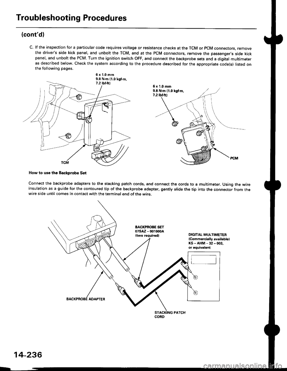
C. lf the inspection for a particular code requires voltage or resistance checks at the TCM or PCM connectors, removethe driver's side kick panel, and unbolt the TCM, and at the PCM connectors, remove the passenger's side kickpanel, and unbolt the PCM. Turn the ignition switch OFF, and connect the backprobe sets and a digital multimeteras described below. Check the system according to the procedure described for the appropriate code(s) listed onthe following pages.
6x1.0mm9.9 N.m {1.0 kgt m,
How to use lhe Backprob€ SE{
Connect the backprobe adapters to the stacking patch cords, and connect the cords to a multimeter, Using the wireinsulation as a guide for the contoured tip of the backprobe adapter, gently slide the tip into the connector from thewire side until comes in contact with the terminal end of the wire.
BACI(PROBE SET07saz - 001 txtoaItwo requirodlDIGITAL MULTIMETER(Commarcially avsibblelKS-AHM-32-(x)3,or oquivalent
6 x 'l,0 mm9.E N.m (1.0 kgf.m,7.2 rbtftt
coRo
14-236
ADAPTER
Page 919 of 2189
Electrical Troubleshooting ('96 - 98 Modelsl
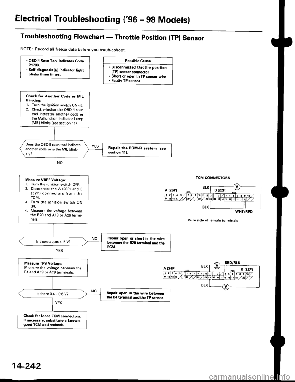
Troubleshooting Flowchart - Throttle position (Tpl Sensor
Possible Cause
. Disconnected throftle position(TPl 3ensor connoctol. Short or open in TP sensor wire. Fauhy TP sensol
TCM CONNECTORS
Wire s;de of female terminals
. OBO ll Scan Tool indic.tes CodeP1790.. Self-diagnosis E indicator lightblinks three times.
Check lor Anothar Code or MILBlinking:1. Turn the ignition switch ON 1 ).2. Check whether the OBD ll scantool indicates another code orthe Malfunction Indicator Lamp(MlL) blinks (see secrion 11).
Does the OBD ll scan tool indicateanothercode oristhe MIL blink-ing?
Repair the PGM-FI systom (3eesection 111.
Measure VREF Voltage:1. Turn the ignition switch OFF.2. Disconnect the A (26P) and B{22P} connectors lrom theTCM.3. Turn the ignition switch ON{fl).4. Measure the voltage bet\iveenthe 820 and A13 or 426 termi-nals,
Repair open or short in thc wireb,stween the Bao tcrminal rnd theECM.
ls lhere approx. 5 V?
Measure TPS Voltago:Measure the voltage between theB4 and A13 or 426 terminals.
Repail open in the wire tr€tweonthe Erl t6.minal ind the TP sen3o..ls there 0.4 - 0.6 V?
Check for loose TCM connectors.lf necessary, substitute a known-good TCM and r6check.
NOTE: Record all freeze data before you troubleshoot.
BLK
WHT/RED
A {26P1
Page 920 of 2189
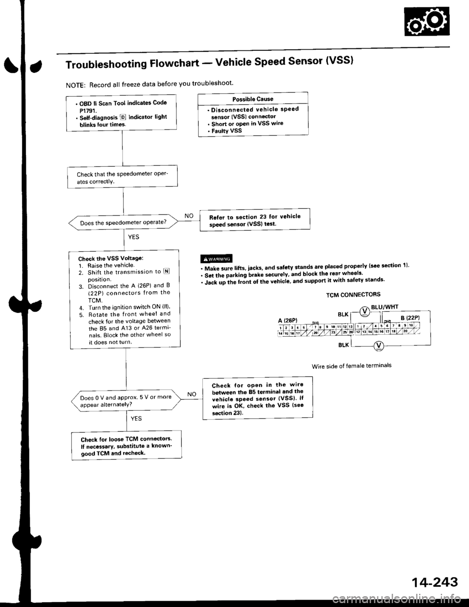
Troubleshooting Flowchart - Vehicle Speed Sensor (VSS)
NOTE: Record all freeze data before you troubleshoot'
Po$rible Ctuse
. Disconnected vehicle speed
sensor (VSS) connectol. Short or open in VSS wire' Faulty VSS
@. Make sure lifts, iacks, and sal€tY stands are placed properly lsoe section 1)'
. Set the parking brake securelv, and block the rear wheels'
. iacr upile rront or the vehicle, and support it with safety st'nds'
TCM CONNECTORS
Wire side of female terminals
. OBD ll Scan Tool indicates Code
P1791.. Setf-diagno3is E indicato. light
blinks tour times.
Refer to seclion 23 for vehicle
soeed sensor IVSSI test
Check the VSS Voltage:
1. Raise the vehicle2. Shift the transmission to lEposrtlon.3. Disconnect the A (26P) and B(22P) connectors from the
TCM.4. Turn the ignition switch ON {ll).
5. Rotate the front wheel and
check for the voltage between
the 85 and 413 or A26 termi-
nals. Block the other wheel so
at does not turn
Check for oP€n in the wire
between the 85 terminal and the
vehicle speed sensor {VSS}. lf
wire is OK, check the vSS (see
soction 23).
Does0Vandapprox 5 V or more
appear alternatelY?
Check for loos€ TCM connedors
lI nec€ssary, substitute a known'
good TCM and recheck.
14-243
Page 922 of 2189
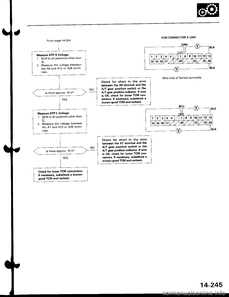
From page l4-244
Measure ATP S Vollage:
1. Shift to all Positions otherthan
2. Measure the voltage between
the A8 and A13 or A26 termi
nals.
Check lor shott in the wire
between the A8 terminal and the
A/T gea. Position switch or the
A/T gear position indicator. lf wire
is OK, check for loose TCM con_
nectors. lI necessary, substitute a
known-good TCM and recheck.
ls there approx. 10 V?
Measure ATP L Voltage:'1. Shift to all positions other than
E-2, Measure the voltage between
the A7 and A13 or A26 termi-
nals.
Check for short in the wi.e
between the A7 terminal and the
A/T gear position switch or the
A/T gear position indicator. lf wire
b OK. check for loose TCM con-
nectors. ff necessary, substilute a
known-good TCM and recheck.
ls there approx. 10 V?
Check lor loose TCM connectors.
lf necessary. substitute a known'
good TCM and recheck.
TCM CONNECTOR A (26P)
Wire side of female termanals
14-245
Page 924 of 2189
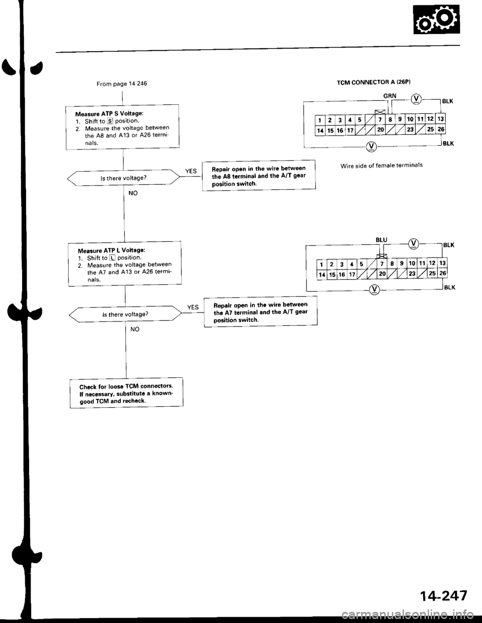
From page 14 246
Moasure ATP S Voltage:
1. Shift to E Position2. Measure the voltage between
the A8 and 413 or 426 termi
nals,
Bepair open in the wir€ between
the A8 t€rminal and the A/T gear
position switch.
Measure ATP L Vohage:
1. Shift to E Position2. Measure the voltage between
the A7 and A13 or 426 termi-
nals.
Repair open in the wire between
the A7 terminal and the A/T geal
Dosition switch
Chock tor loose TCM connectors.
lf necessary, substitute a l(nown-
good TCM and recheck,
TCM CONNECTOR A l26p)
Wire side of female terminals
14-247
Page 926 of 2189
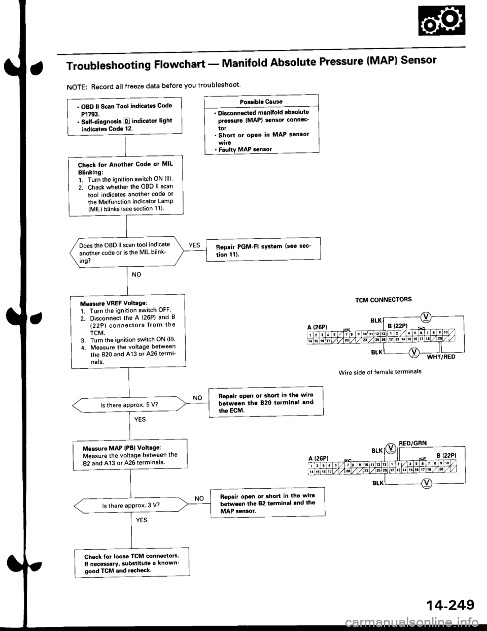
Troubleshooting Flowchart - Manifold
NOTE: Record all freeze data before you troubleshoot
Absolute Pressure {MAPI Sensor
TCM CONNECTORS
Wire side of female terminals
PG.iblo Cau3€
. Dkconnoctod manilold .bsoluto
ore33urc IMAP) sensor connoc'
lor. Short or opcn in MAP s.nsor
MAP sen3or
. OBD ll Scan Tool indicates Code
P1793,. self-diagno3b E indicato. light
indicat€s Code 12.
Chock tor Another Cod€ or MIL
Blinking:1. Turn the ignition switch ON (ll).
2. Check whether the OBD ll scan
tool indicates another code or
the Mal{unction Indicator LamP(MlL) blinks (sse section 11).
Does the OBD llscan tool indicate
another code or isthe lVlL blink-
in9?
Measure VREF voltage:
1. Turn the ignition switch OFF.
2. Disconnect the A (26P) and B
(22P) connectors trom the
TCM.3. Turn the ignition switch ON (ll).
4, Measure the voltage between
the B2O and A13 or A26 termr
nals.
R€pair opon or 3hort in the wire
botwoan the 820 t€.minal and
the EcM.lsthere aPprox.5 V?
Msasure MAP IPB) volt.ge:
Measure the voltage betlveen the
82 and A13 or 426 terminals.
Repair opon ot shorl in the wiro
betwesn the 82 torminal end th€
MAP sensol.ls there approx. 3 V?
Check for loo3e TCM conn€stors.
lf nec*sarY, sub3titute a known'
good TCM and rechock.
WHT/RED
14-249
Page 930 of 2189
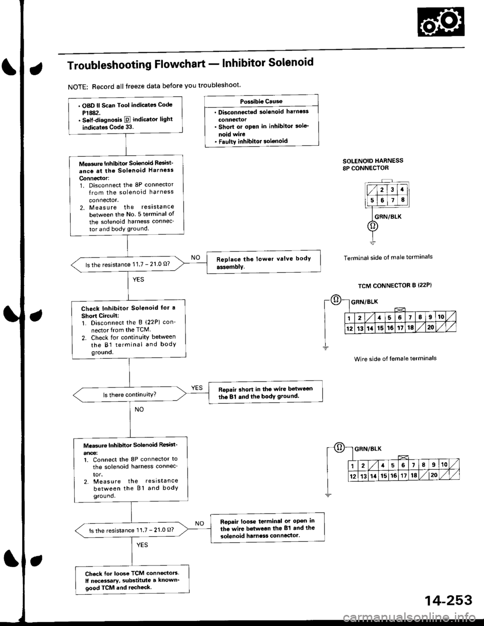
Troubleshooting Flowchart - Inhibitor Solenoid
NOTE: Record all treeze data betore you troubleshoot
Po$ibls Cause
. Dbconnected solenoid hatness
connedor' Short or opon in inhibitor sole'
noid wire. Faultv inhibitor solenoid
SOLENOID HARNESS8P CONNECTOR
Terminal side of male terminals
. OBD ll Scan Tool indic.td Code
P1882.. Selt-di.gnGis E indicator lighl
indic.tos Code 33.
Mea3ure Inhibhor Solenoid Resid-
ance at the sol€noid Harness
Connector:1. Disconnect the 8P connector
from the solenoid harness
connector.2. Measure the reslstance
betlveen the No 5 terminal of
the solenoid harness connec-
tor and body ground.
ls the resistance 11.7 - 21 0 0?
Check Inhibitor Solenoid lor a
Short Circuii:1. Disconnect the B (22P) con-
nector from the TCM.
2. Check for continuity between
the B1 terminal and bodygro!no.
Repair rhort in the wire ltetwegn
the 81 dnd the bodY ground.
Mea$rr€ Inhibitor Solenoid ResBt'
anoe:1. Connect the 8P connector to
the solenoid harness connec_
IOr.2. Measure the resistance
between the Bl and bodyground.
Reoair loose terminal or open in
the wire betwean the 81 and the
solenoid hame3s connector'ls the resistance 11.7 - 21.0 O?
Ch6ck for loose TCM connectors.
ll necessary, substhule a known_good TCM and techeck.
Wire side of female terminals
14-253
Page 934 of 2189
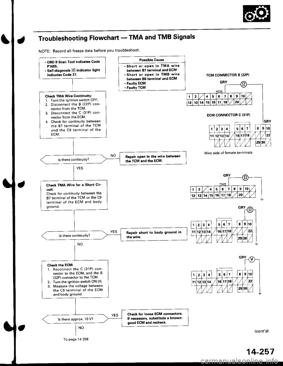
Troubleshooting Flowchart - TMA and TMB Signals
NOTE: Record all freeze data before you troubleshoot'
Possible Cause
. Shorl or op.n in TMA wi.o
botwo6n 87 terminal and ECM. Short or open in TMB wiro
bdtwoon BG to.min.l .nd ECM. F.ulty ECM. Faulty TCM
TCM CONNECTOR B (22P)
GRY
Wire side oI temale terminals
o
I2a58910
1213111516171820
GRY
ECM CONNECTOR C 13lPI
123a56l89r0
1112t3la1618//
29130 /
::)
I2a568910
12t3141516171820
. OBD ll Scsn Tool indicate3 Codo
P1655.. Self-diagnosb E indicator light
indicales Cod6 37.
Check TMA Wire Continuity:1. Turn the ignition switch OFF.
2- Disconnect the I (22P) con-
nector lrom the TCM
3. Disconnect the c (31P) con'
nector from the ECM
4. Check for continuity between
the 87 terminal of the TCM
and the Cg terminal oI the
ECM,
Ropail open in the wire betwcen
the TCM and the ECM.
Check TMA Wir€ for a Short Cir-
cuit:Check for continuity between the
87 terminal of the TCM or the Cg
terminal ol the ECM and bodyground.
check rhe EcM:1. Reconnect the C (31P) con'
nector to lhe ECM, and the B(22P) connector to the TCM
2. Turn the ignition switch ON (ll).
3. Measure the voltage between
the C9 terminal oI the ECM
and body ground.
Chock tor loose ECM connectors.
lf nscossary, subdituta a known'good ECM .nd lecheck.ls there approx. 10 V?
To page 14 258
(cont'd)
14-257