Engine remove HONDA CIVIC 1997 6.G Workshop Manual
[x] Cancel search | Manufacturer: HONDA, Model Year: 1997, Model line: CIVIC, Model: HONDA CIVIC 1997 6.GPages: 2189, PDF Size: 69.39 MB
Page 1025 of 2189
l.
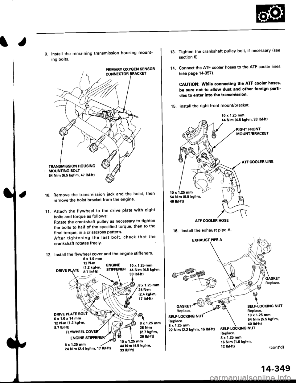
9. Install the remaining transmission housing mount-
ing bolts.
PRIMARY OXYGEN SENSOR
Remove the transmission jack and the hoist. then
remove the hoist bracket from the engine'
Attach the flvwheel to the drive plate with eight
bolts and torque as follows:
Rotate the crankshaft pulley as necessary to tighten
rhe bolts to half of the specified torque, then to the
final torque, in a crisscross pattern.
After tightening the last bolt. check that the
crankshaft rotates freelY.
10.
11.
12. Install the flywheel cover and the engine stiffeners
DRIVE
6xl.0mm12 N.m
- l12 kgf'm'rE 8.7 tbf.ftl
ENGINESTIFfENEB10 x 1.25 mmart N.m la.s kgt.m,33 tbtftt
8 x 1.25 mm24 N.m(2.1 kgf'm,17 tbt.ftt
DRIVE PI.ATE BOLT
6x1.0x14mm12 N.m {1.2 kgt m.
8.7 lbf,ftl8 x 1.25 mm26 N.m
12.7 kqfin,20 rbt'ftlFLYUTHEEL
ENGINE STIFFENER
8 x 1.25 mm10 x 1.25 mmr,a N.m {4,5 kgf m,
33 tbf.ftl
TRANSMISSION HOUSING
MOUNNNG BOLT
6il N.m {6.5 kgf.m, 47 lbf'ftl
24 N.m (2.4 kgt'm, '17 lbf'ftl
22 N.m t2.2 kgl m, 16lbf'ftl
14-349
13.
14.
Tighten the crankshaft pulley bolt, if necessary (see
section 6).
Connect the ATF cooler hoses to the ATF cooler lines
(see page 14-357).
CAUTION: Whilo connecting the ATF cooltr hGes,
b€ sure not lo allow dust and other loreign parti-
cles to entg. into the transmission.
15. Installthe right front mounvbracket'
10 x 1.25 mm
a,r N.m {4.5 kgf'm,33 lbt ftl
RIGHT FRONTMOUNT/BRACKET
ATF COOLER LINE
10 x 1 .25 mm54 N.m {5.5 kgt'm,
4{) tbl.ftt
ATF COOI,TR HOSE
16. Installthe exhaust PiPe A.
EXHAUST PIPE A
GASKETReplace.
@
\SELF.LOCKING NUTReplace.10 x 1.25 mm5/a N.m {5.5 kgt m,irc lbf.ft)
(cont'dl
*s$o
oor*rr-@Replace.
SELF.LOCKINGReplace.8 x 1.25 mmSELF.LOCKING NUT
Replace.8 x 1.25 mm16 N.m {1.6 kgl'm,12 tbl.ftt
Page 1027 of 2189

22. Install the shift cable end on the control lever, and
install the shift cable on the shift cable bracket'
CAUTION: Take care not to bend the shift cable'
23. lnstall the clip in the direction shown.
LOCKNUT
SHIFI CABLE 29 N m {3.0 kg{ m, 22lblftl
SHIFT CABLEERACKET
WASHERIPLASTIC)
CONTROL LEVER
24, Connect the solenoid harness connector. the drive
pulley speed sensor connector. and the ground
cable terminals.
6x1.0mm12 N.m {1.2 kgf.m.8,7 rbtft)
GROUND CABLETERMINAL 6x1.0mm
GROUNDTERMINAL
12 N.m {1.2 kgf'm,8.7lbtfrl
DRIVE PULLEYSPEED SENSORCONNECTOR
SOLENOID HARNESS
CONNECTOR
25. Connect the starter motor cable on the starter motor.
and install the cable holder.
NOTE: When installing the staner motor cable. make
sure that the crimped side of the ring terminal is
facing out (see section 23).
STARTEB
BMOUNTING NUT
9 N.m (0.9 kgf m,7 lbf ft)
26. Install all removed connectors and clamps'
27. Install the distributor.
28. Install the intake air duct and air cleaner housing
29.
assemDly.
Refill the transmission with the recommended
Genuine Honda CVT Fluid (see page 14-2991
CAUTION: While filling the CvT Fluid, bs surs not io
allow dust and other fotoign particles to entor into
the transmission.
Connect the battery positive (+) terminal first, then
the negative (-l terminal to the battery'
Check the ignition timing (see section 23).
Start the engine. Set the parking brake, and shift the
transmission through all gears three times Check
shift cable adjustment (see page 14-355).
Check the front wheel alignment (see section 18)
Let the engine reach operating temperature (the
radiator fan comes on) with the transmission in lXl
or E position, then turn it off and check fluid level'
Perform the start clutch calibration procedure on
page 14-293.
Road test as described on pages 14-296 and 14-297
30.
31.
34.
36.
STARTER MOTOR
14-351
Page 1029 of 2189
![HONDA CIVIC 1997 6.G Workshop Manual l.
17.Make sure the transmission is in the E] position.
Fill the transmission with cvT Fluid, and run the
engine for 30 seconds or until approximately 0 95 {
(1.0 US qt.,0.8 lmp qt.) is discharged.
Re HONDA CIVIC 1997 6.G Workshop Manual l.
17.Make sure the transmission is in the E] position.
Fill the transmission with cvT Fluid, and run the
engine for 30 seconds or until approximately 0 95 {
(1.0 US qt.,0.8 lmp qt.) is discharged.
Re](/img/13/6068/w960_6068-1028.png)
l.
17.Make sure the transmission is in the E] position.
Fill the transmission with cvT Fluid, and run the
engine for 30 seconds or until approximately 0 95 {
(1.0 US qt.,0.8 lmp qt.) is discharged.
Remove the drain hose, and reconnect the cooler
return hose to the transmission (see page 14-355)
Refill the transmission with CVT Fluid to the proper
level (see page 14-299).
18.
'19.
.l ,
TOOL MAINTENANCE
1. Empty and rinse after each use. Fill the can with water
and pressurize the can. Flush the discharge line to
ensure that the unit is clean.
2, lf discharge liquid does not foam, the orifice may be
blocked.
3. To clean, disconnect the plumbing from the tank at
the large couPling nut.
FILTER
\
\- 0--D
i
I
O.RING
Remove the in-line tilter from the discharge side and
clean if necessary'
The fluid orifice is located behind the filter. Clean it
with the pick stored in the bottom of the tank han-
dle. or blow it clean with air. Securely reassemble
all parts.
COUPLINGNUT
II
-@q
\ORIFICE
FILLER CAP
14-353
Page 1031 of 2189
t
Adjustment
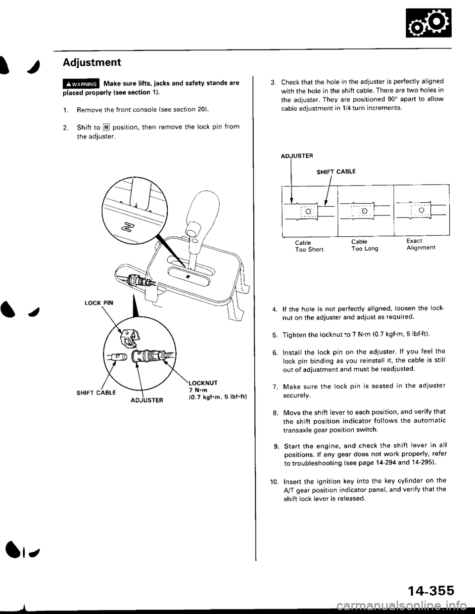
!@ Make sure lifts, jacks and safety stands are
placed properly (see section 1).
l. Remove the front console (see section 20).
2. Shift to I posirion, then remove the lock pin from
the adjuster.
SHIFT CAELE
l,
,l
{0.7 kgf.m, 5lbf'ltl
3. Check that the hole in the adiuster is perfectly aligned
with the hole in the shift cable. There are two holes in
the adjuster. They are positioned 90" apart to allow
cable adjustment in 1/4 turn increments.
lf the hole is not perfectly aligned, loosen the lock-
nut on the adjuster and adjust as required.
Tighten rhe locknut to 7 N.m (0.7 kgim,5 lbf'ft).
Install the lock pin on the adjuster' lf you feel the
lock pin binding as you reinstall it. the cable is still
out of adjustment and must be readjusted
Make sure the lock pin is seated in the adiuster
securery.
lMove the shift lever to each position, and verify that
the shift position indicator follows the automatlc
transaxle gear position switch.
Start the engine, and check the shift lever in all
positions. lf any gear does not work properly, refer
to troubleshooting (see page 14-294 and 14-295).
Insert the ignition key into the key cylinder on the
Aff gear position indicator panel, and verify that the
shift lock lever is released.
7.
10.
14-355
Page 1089 of 2189
IRack Guide Adjustment
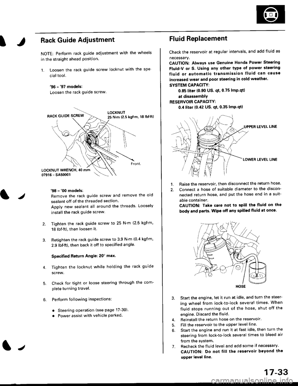
NOTE: Perform rack guide adjustment with the wheels
in the straight ahead Position.
1. Loosen the rack guide screw locknut with the
cialtool.
'96 - '97 models:
Loosen the rack guide screw
'98 - '00 models:
Remove the rack guide screw and remove the old
sealant off of the threaded section.
Apply new sealant all around the threads. Loosely
installthe rack guide screw
Tighten the rack guide screw to 25 N'm (2.5 kgf'm.
18 lbf.ft), then loosen it.
Retighten the rack guide screw to 3 9 N'm (0.4 kgim,
2.9 lbf.ft), then back it off to specified angle.
Specified Return Angle: 20" max.
Tighten the locknut while holding the rack guide
screw.
Check for tight or loose steering through the com-
plete turning travel.
Perform following insPections:
. Steering operation (see page 17-30).
. Power assist with vehicle parked.
4.
LOCKNUT WRENCH, 40 mm
lr
17-33
Fluid Replacement
Check the reservoir at regular intervals, and add fluid as
necessary.
CAUTION: Always us€ Genuine Honda Power Stearing
Fluid-V or S. Using any other type of power sto€ring
tluid or automatic transmission lluid can cause
increased wear and poor steering in cold weathor.
SYSTEM CAPACITY:
0.85 liter 10.90 US' qt,0.75 lmp'qt)
at disassembly
RESERVOIR CAPACITY:
0.4 liter (0.42 US. qt, 0.35 lmP.qt)
LEVEL LINE
LOWER LEVEL LINE
1. Raise the reservoir, then disconnect the return nose.
2. Connect a hose of suitable diameter to the discon-
nected return hose, and put the hose end in a suit-
able container.
CAUTION: Take care not to spill tho fluid on the
body and parts. Wipe off any spill€d fluid at oncs'
3. Start the engine, let it run at idle, and turn the steer-
ing wheel from lock-to-lock several times When
fluid stops running out of the hose, shut off the
engine, Discard the fluid.
4. Reinstall the return hose on the reservoir'
5. Fill the reservoir to the upper level line.
6. Start the engine and run it at fast idle, then turn the
steering trom lock-to-lock several times to bleed air
trom the system.
7. Recheck the fluid level and add some it necessary.
CAUTION: Do not fill the reservoir beYond the
upper l€vel line.
HOSE
Page 1096 of 2189
Power Steering Pump
RemovaUlnstallation
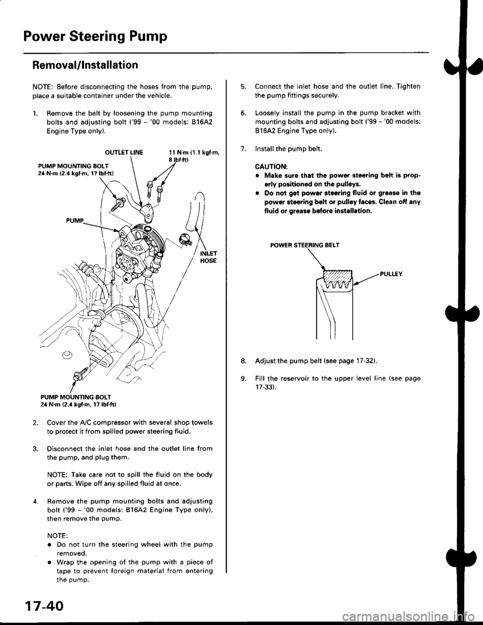
NOTE: Eefore disconnecting the hoses from the pump,
Dlace a suitable container under the vehicle.
1. Remove the belt by loosening the pump mounting
bolts and adjusting bolt ('99 -'00 models: 81642
Engine Type only).
OUTLET LINE11 N.m {1.1 kgf'm,8
L
PUMP MOUNTING BOLT24 N.m (2.4 kgl.m, 17 lbf ft)
2. Cover the Ay'C compressor with several shop towels
to protect it from spilled power steering fluid.
3. Disconnect the inlet hose and the outlet line from
the pump, and plug them.
NOTE: Take care not to spill the fluid on the body
or parts, Wipe off any spilled fluid at once.
4. Remove the pump mounting bolts and adjusting
bolt ('99 -'00 models: 816A2 Engine Type only),
then remove the pump.
NOTE:
. Do not turn the steering wheel with the pump
removeo.
. Wrap the opening of the pump with a piece of
tape to prevent foreign material from entering
the pump.
17-40
1.
8.
Connect the inlet hose and the outlet line. Tiqhten
the pump fittings securely.
Loosely install the pump in the pump bracket with
mounting bolts and adjusting bolt ('99 -'00 models:
81642 Engine Type only).
Installthe pump belt.
CAUTION:
. Make sure that the power steering belt is prop-
orly positioned on the pulleys.
. Do not get power stoering tluid or grease in the
power steering bsh or pulley faces. Clean off any
fluid or grease before installrtion.
Adjust the pump belt (see page 17-32).
Fill the reservoir to the upper level line (see page
Page 1135 of 2189
)
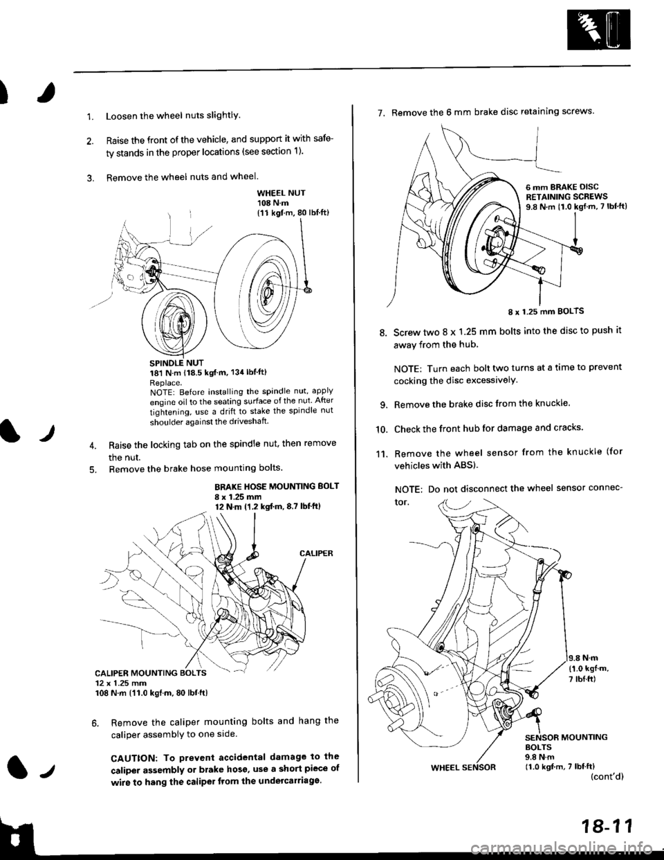
1.Loosen the wheel nuts slightlY.
Raise the front of the vehicle, and support it with safe-
ty stands in the proper locations (see section 1).
Remove the wheel nuts and wheel.3.
l)
WHEEL NUT'108 N.m
18'l N.m 118.5 kgf m, 134lblfti
Replace.NOTEI Before installing the spandle nut, apply
engine oil to the seating surface of the nut After
tightening, use a drift to stake the spindle nut
shoulder againsl the driveshaft
Raise the locking tab on the spindle nut, then remove
the nut.
Remove the brake hose mounting bolts.
BRAKE HOSE MOUNTING BOLT
I x 1.25 mm12 N.m (1,2 kgtm,8,7 lbf'ftl
6. Remove the caliper mounting bolts and hang the
caliper assembiy to one side
CAUTTON: To prevent accidental damage to the
caliper assembly or brake hoso' use a short piece of
wire to hang the caliPer tlom lhe undelcarriage.
{11 kgf m, 80 lbl.ft)
CALIPER MOUNTING BOLTS12 x 1.25 mm108 N.m {'11.0 kgtm, 80 lbt.ft)
7. Remove the 6 mm brake disc retaining screws.
8.
I x 1.25 mm BOLTS
Screw two 8 x 1.25 mm bolts into the disc to push it
away from the hub,
NOTE: Turn each bolt two turns at a tame to prevent
cocking the disc excessivelY.
Remove the brake disc from the knuckle.
Check the front hub for damage and cracks.
Remove the wheel sensor from the knuckle (for
vehicles with ABS).
NOTE: Do not disconnect the wheel sensor connec-
tor.
N.m
6 mm BRAKE OISCRETAINING SCREWS9.8 N.m t1.0 kgf.m, 7 lbf'ft)
{'1.0 kgf m,
7 tbf.ft)
10.
11.
MOUNTING
WHEEL
BOLTS9.8 N.m11.0 kgf,m, 7 lbf'ft)(cont'd)
Page 1147 of 2189
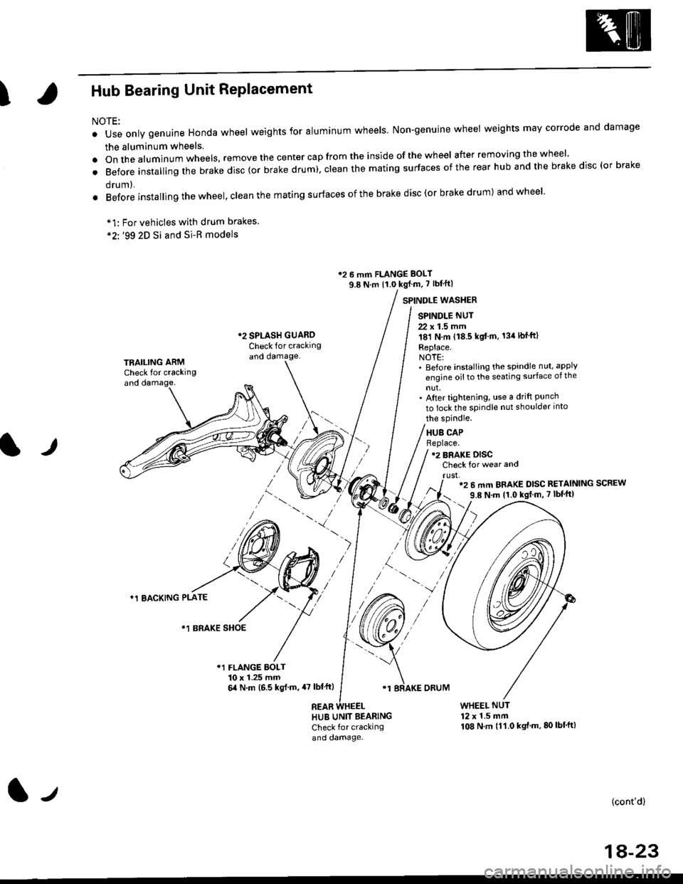
IHub Bearing Unit RePlacement
For vehicles with drum brakes.'99 2D Si and Si-B models
NOTE:
o Use only genuine Honda wheel weights for aluminum wheels Non-genuine wheel weights may corrode and damage
the aluminum wheels.
.onthea|uminumwhee|s,removethecentercapfromtheinsideoftheWhee|afterremovingthewhee|'
. Before insta||ing the brake disc (or brake drum), c|ean the mating surfaces of the rear hub and the brake disc (or brake
orum,.
. Before installing the wheel, clean the mating surfaces ofthe brake disc(or brake drum) andwheel'
*1:
*2'.
12 6 mm FLANGE BOLT
9.8 N.m {1.0 kgf m, 7 lbf'ft|
*2 SPLASH GUAROCheck for crackingand damage.
SPINDLE WASTIER
SPINDLE NUT
22 x 1.5 mm181 N,m (18.5 kgt'm. 134lbfft)
Replace.NOTE:' Before installing the spindle nut, apply
engine oil to the seating surface of the
nut,' After tightening, use a drift Punchto lock the spindle nut shoulder into
TRAILING ARMCheck for crackingand oamage,
lr
the spindle.
HUB CAPBeplace.12 BRAKE DISCCheck for wear and
rust,'2 6 mm BRAKE DISC RETAINING SCREW
9.8 N'm 11.0 kgt m, 7 lbf'ft|
)
*1 BACKING PLATE
/\*1 BRAKE SHOE
r1 FLANGE BOLT10 x 1.25 mm6,0 N.m (6.5 ksl.m,47 lbl'ftl
REAB
'1 BRAKE ORUM
HUB UNIT BEARING
Check for crackingand damage.
WHEEL NUT12 x 1.5 mm108 N.m {11.0 kgt'm.80lbt'ft)
(cont'd)
1A-23
l-t
Page 1148 of 2189
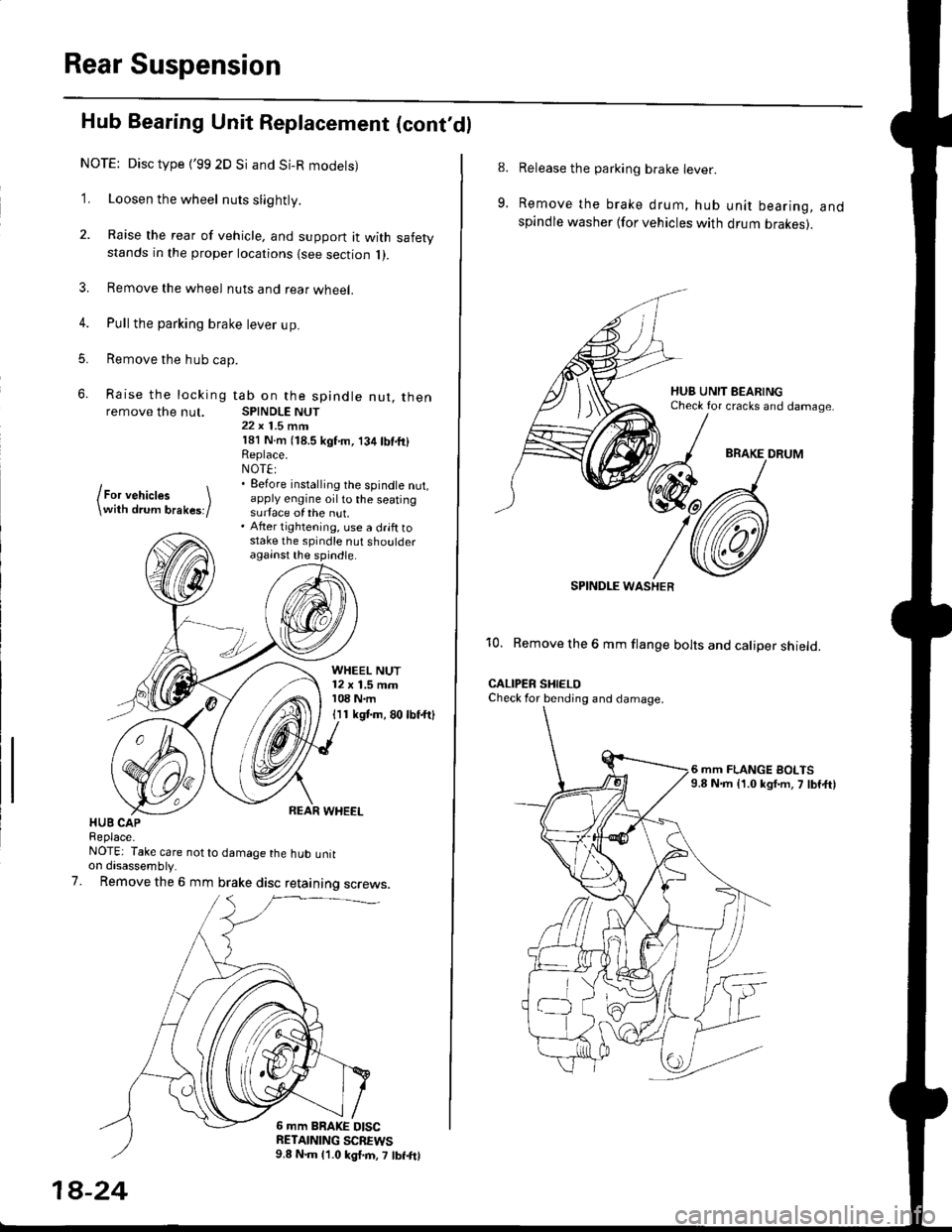
Rear Suspension
Hub Bearing Unit Replacement (cont'dl
NOTE: Disc type {'99 2D Si and Si-R modets)
1. Loosen the wheel nuts slightly.
2. Raise the rear of vehicle, and support it with safetystands in the proper locations {see section 1).
3. Remove the wheel nuts and rear wheel.
4. Pull the parking brake lever up.
5. Remove the hub cap.
6. Raise the locking tab on the spindle nut, thenremove the nut. SPINDLE NUT22 x 1.5 mrn181 N.m (18.5 kgf'm, 134lbf.fi)Replace.NOT€:. Eefore installing the spindle nut,apply engine oil to the seatingsurface of the nut.. After tightening, use a drift tostake the spindle nut shoulderagainst the spindle.
lFor vehictes \\with drum brakes;/
WHEEL NUT12 x 1.5 mm108 N.m
I I 1 kgt m, 80 lbf.ftl
HUB CAPReplace-NOTE: Take care not to damage the hub untton disassembly.
Remove the 6 mm brake disc retaining screws.7.
6 mm BRAKE DISCRETAINING SCBEWS9.8 N.m 11.0 kgl.m, 7 lbf.frl
1A-24
8.
9.
Release the parking brake lever.
Remove the brake drum, hub unit bearing, andspindle washer lfor vehicles with drum brakes).
BRAKE DRUM
SPINDI-E WASHER
10. Remove the 6 mm flange bolts and caliper shield.
CALIPER SHIELOCheck for bending and damage.
6 mm FLANGE BOLTS9.8 N.m {1.0 kgf.m, 7 lbf,ft)
Page 1159 of 2189
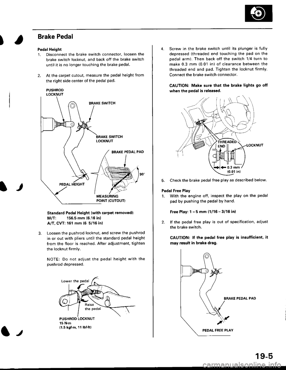
)
Brake Pedal
Pedal Height
1. Disconnect the brake switch connector, loosen the
brake switch locknut, and back off the brake switch
until it is no longer touching the brake pedal,
2. At the carpet cutout, measure the pedal height from
the right side center of the pedal pad.
PUSHRODLOCKNUT
Standard Pedal Height (with carpet removed):
M/T: 156.5 mm 16.16 inl
A/T, CVT: 161 mm (5 5/16 in)
3. Loosen the pushrod locknut, and screw the pushrod
in or out with pliers until the standard pedal height
from the floor is reached. After adjustment, tighten
the locknut firmly.
NOTE: Do not adiust the pedal height with the
Dushrod depressed.
It
PUSHROO LOCKNUT15 N.m(1.5 kgf.m. 11 lbI.ft)
POINT ICUTOUTI
4. Screw in the brake switch until its plunger is fully
depressed (threaded end touching the pad on the
pedal arm). Then back off the switch 1/4 turn to
make 0.3 mm (0.01 in) of clearance between the
threaded end and pad. Tighten the locknut firmly.
Connect the brake switch connector.
CAUTION: Make sure that the brake lights go off
when the pedal is released.
LOCKNUT
5. Check the brake pedal free play as described below.
Pedal Free Plsy
1. With the engine off, inspect the play on the pedal
pad by pushing the pedal by hand.
Free Play: 1 - 5 mm (1/16 - 3/16 inl
2. lf the pedal free play is out of specitication, adjust
the brake switch.
CAUTION: lf the pedal free play is insufficient, it
may result in brake drag.
BRAKE PEDAL PAO
)
19-5
*0.3 mm(0.01 in)