Engine oil service HONDA CIVIC 1997 6.G User Guide
[x] Cancel search | Manufacturer: HONDA, Model Year: 1997, Model line: CIVIC, Model: HONDA CIVIC 1997 6.GPages: 2189, PDF Size: 69.39 MB
Page 206 of 2189
Main Bearings
4.
Glearance
1.To check main bearing-to-journal oil clearance.
remove the main caps and bearing halves.
Clean each main journal and bearing half with a
clean shop towel.
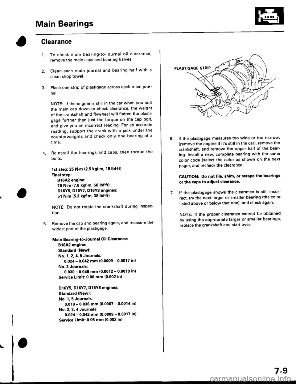
Place one strip of plastigage across each main jour-
na l.
NOTE: lf the engine is still in the car when you bolt
the main cap down to check clearance, the weight
of the crankshaft and flvwheel will flaften the plasti-
gage further than just the torque on the cap bolt.
and give you an incorrect reading. For an accurate
reading, support the crank with a jack under the
counterweights and check only one bearing at a
time,
Reinstall the bearings and caps, then torque the
bolts.
lst step: 25 N'm (2.5 kgl'm. 18 lbf'ft)
FinalsteD:
B16A2 engine:
76 N.m (7.8 kgf.m, 56 lbf'ft)
D16Y5, Dl6Y7, D16Y8 engines:
51 N.m (5.2 kgf'm, 38 lbf'ft)
NOTE: Do not rotate the crankshaft during inspec-
tron.
Remove the cap and bearing again, and measure the
widest part ot the plastigage.
Main Boaring-toJournal Oil Clearance:
816A2 engine:
Standald {New}:
No. l, 2, 4, 5 Journals:
O.O2,l - 0.042 mm 10'00(B - 0.0017 in)
No. 3 Journals:
0.030 - 0.048 mm {0'0012 - 0'0019 in)
Servico Limit: 0.06 mm {0.002 in,
Dl6Y5, Dl6
r, Dl6Y8 engines:
Standard (Nsw):
No. 1,5 Journals:
0.018 - 0.035 mm {0.0007 - 0'001'[ in)
No. 2. 3, 4 Journals:
0.02,1 - 0.0,(2 mm {0'0009 - 0.0017 in}
Service Limit: 0.05 mm (0.002 in)
\
7-9
7.
lf the plastigage measures too wide or too narrow,
(remove the engine if it's still in the car), remove the
crankshaft, and remove the upper half of the bear-
ing. Install a new. complete bearing with the same
color code {select the color as shown on the next
page), and rechsck the clearance.
CAUTION: Do nol fil€, shim, or scrape the bearings
or tho cap3 to adiust cleatanc€.
lf the plastigage shows the clearance is still incor-
rect, try the next larger or smaller bearing (the color
listed above or below that one), and check again
NOTE: lf the proper clearance cannot be obtained
by using the appropriate larger or smaller bearings,
replace the crankshaft and start over.
Page 208 of 2189
Connecting Rod Bearings
Clearance
Remove the connecting rod cap and bearing half
Clean the crankshaft rod iournal and bearing half
with a clean shop towel.
Place plastigage across the rod journal.
Reinstall the bearing half and cap, and torque the nuts.
Torque
Bl6A2 engine:
40 N.m (4.1 kgl.m, 30 lbf'ft)
Dr6Y5, D16Y7, D16Y8 enginss:
31 N'm (3.2 kgf.m, 23 lbf ftl
NOTE| Do not rotate the crankshaft during inspection.
Remove the rod cap and bearing half and measure
the widest part of the plastigage.
Connecting Rod Bearing-to.Journal Oil Glearance:
816A2 engine:
Standard lNewl: 0.032 - 0.050 mm
10.0013 - 0.0020 in)
Service Limit: 0.06 mm 10.002 inl
D16Y5, D16Y7, D16Y8 engines:
Standard lNew): 0.020 - 0.038 mm
(0.0008 - 0.0015 in)
Service Limit 0.05 mm 10.002 inl
'1.
4.
lf the plastigage measures too wide or too narrow'
remove the upper half of the bearing, install a new,
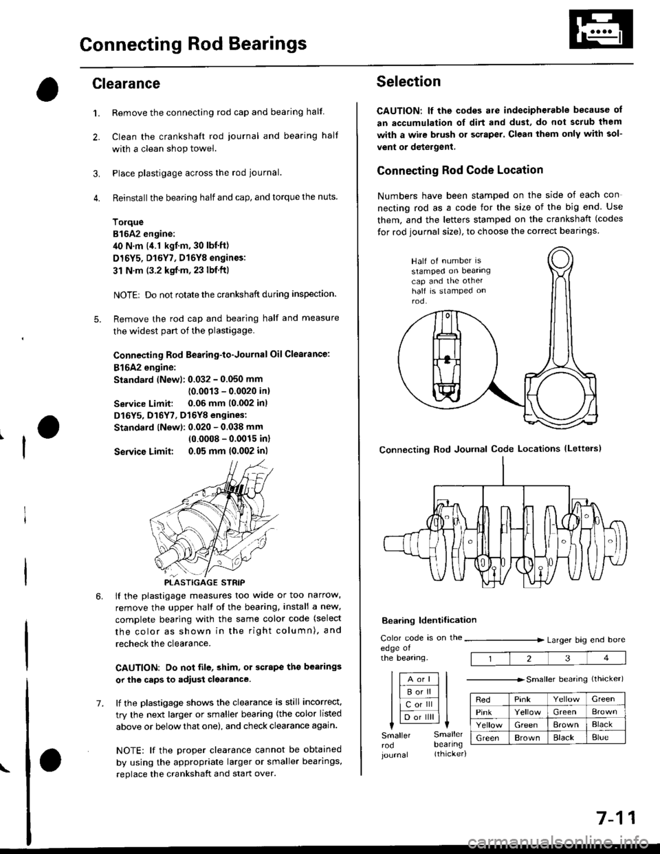
complete bearing with the same color code (select
the color as shown in the right column), and
recheck the clearance.
CAUTION: Do not lile, shim, or scrape the bearings
or the caps to adiust clgarance.
lf the plastigage shows the clearance is still incorrect.
try the next larger or smaller bearing (the color listed
above or below that one), and check clearance again.
NOTE: lf the Droper clearance cannot be obtained
by using the appropriate larger or smaller bearings,
replace the crankshaft and start over.
PLASTIGAGE STRIP
\
7.
7-11
Selection
CAUTION: lf the codes are indecipherable because of
an accumulation of dirt and dust, do not sclub them
with a wile brush or scraper. Clean them only with sol-
vent or detergent,
Connecting Rod Code Location
Numbers have been stamped on the side of each con
necting rod as a code for the size of the big end Use
them, and the letters stamped on the crankshaft (codes
for rod journal size), to choose the correct bearlngs
Half of number ls
stamped on bearingcap and the otherhalf is stamped onrod.
Bearing ldentilication
Color code is on theedge ofthe bearing.
lfA--;T] |
lle"'tt l;llcorlll ll
I lD;;ilril |l-l
Larger brg end bore
Smaller Smallerrod bearlngjournal (thicker)
---------------- Smallerbearing{thrcker)
RedPinkGreen
PinkGreen
GreenErownBlack
GreenBrownBlackBlue
1234
Connecting Rod Journal Code Locations (Lettels)
Page 211 of 2189
Crankshaft
Inspection
. Clean the crankshaft oil passages with pipe cleaners
or a suitable brush.
. Check the keyway and threads.
Alignment
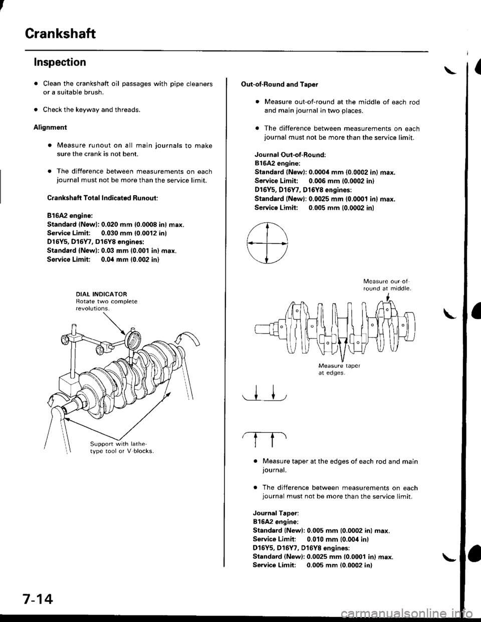
. Measure runout on all main journals to make
sure the crank is not bent.
. The difference between measurements on eachjournal must not be more than the service limit.
Crankshaft Total Indicated Runout:
Bl6A2 engine:
Standard (Newl: 0.020 mm {0.0008 in} max.
Service Limit: 0.030 mm {0.0012 inl
D16Y5, D15Y7, D15Y8 engines:
Standsrd {New): 0.03 mm (0.001 in} max.
Service Limit; 0.0i1 mm 10.002 in)
Support with lathetype tool or V blocks.
7-14
Out-of-Round and Tapet
. Measure out-of-round at the middle of each rod
and main journal in two places.
a The difference between measurements on eachjournal must not be more than the service limit.
Joulnal Out-of-Round:
81642 engine:
Standard (New): 0.0004 mm {0.0002 in) max.
Service Limit: 0.006 mm {0.0002 in)
Dr6Y5, Dl6Y7, D16Y8 engines:
Standard (Newl: 0.0025 mm (0.0001 inl max.
Service Limh: 0.005 mm (0.0002 inl
round at middle.
. Measure taper at the edges of each rod and mainjournal.
. The difference between measurements on eachjournal must not be more than the service limit.
JournalTaDer:
B16A2 ongine:
Standard lNewl: 0.005 mm (0.0002 inl max.
Service Limit: 0.010 mm (0.00i1 inl
D16Y5, D16Y7, Dl6YB engines:
Standard (New): 0.0025 mm {0.0001 in) max.
Service Limit: 0.005 mm (0.0002 in)
\
Page 214 of 2189
Cylinder BlockPiston Pins
Bore Honing
1.Measure cylinder bores as shown on page 7-16. lf the
block is to be reused, hone the cylinders and remea-
sure the bores.
Hone cylinder bores with honing oil 8nd a fine (400
grit) stone in a 60 degree cross-hatch pattern.
NOTE:
. Use only a rigid hone with 400 grit or finer stone
such as Sunnen, Ammco, or equivalent.
. Do not use stones lhat are worn or broken.
When honing is complete, thoroughly clean the
engine block of all metal particles. Wash the cylin-
der bores with hot soapY water, then dry and oil
immediately to prevent rusting.
NOTE: Never use solvent. it will only redistribute the
grit on the cylinder walls.
lf scoring or scratches are still present in cylinder
bores after honing to the service limit, rebore the
cylinder block.
NOTE: Some light vertical scoring and scratching is
acceptable if it is not deep enough to catch your fin-
gernail and does not run the full length of the bore.
CYLINOES BLOCK
CYLINDER
NOTE:
. After honing, clean the cylinder thoroughly with
soapy warer.
. Onlv a scored or scratched cylinder bore must be
noneo.
Removal
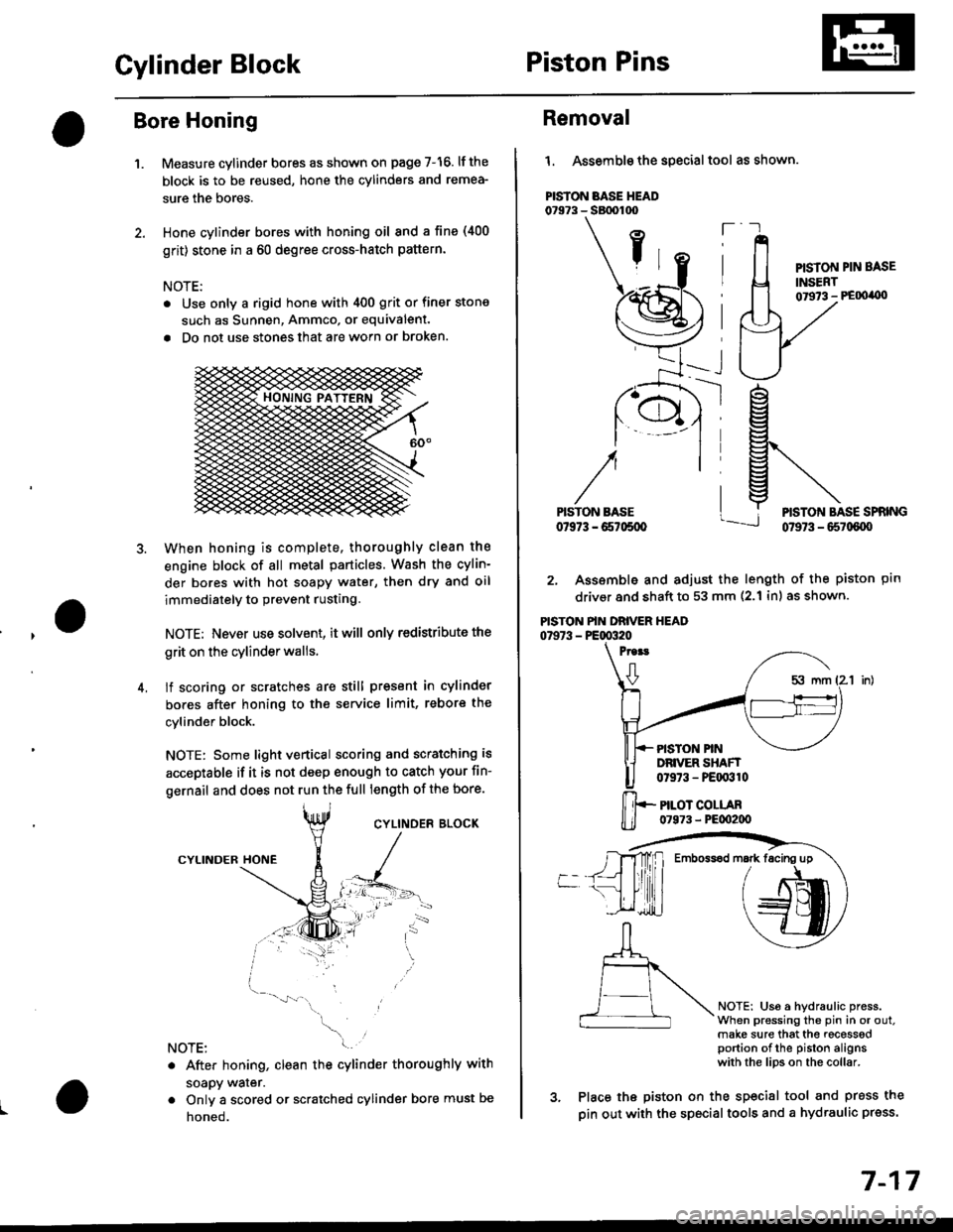
l. Assemble the special tool as shown.
PISTON BASE HEAD07973 - SBtx)too
ft
PISTON PIN BASE
INSERT01973 - PE00'0)
ptn
NOTEi Us6 a hydraulic press.When pressing the pin in or out.make sure that the recesssdportion of the piston alignswith the lips on the collar.
rg
g\
lj*N*,""
2. Assemble and adjust the length of the piston
driver and shaft to 53 mm (2.1 inl as shown.
PISTON PIN DRIVER HEAD07973 - PE00320
Proat
0
PISTON PINDRIVER SHAFT0t973 - PEqr310
PILOT COLLAR07973 - PE00200
3. Place the piston on the sp€cial tool and press the
pin out with the special tools and a hydraulic press.
Emboss6d mark facing up
7-17
Page 217 of 2189
Piston Rings
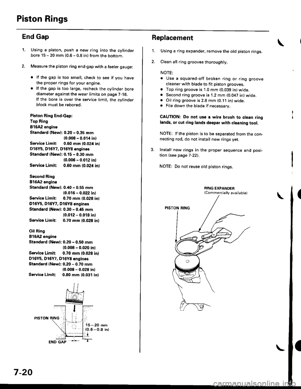
End Gap
1.Using a piston, push a new ring into the cylinderbore 15 - 20 mm (0.6 - 0.8 in) from the bottom.
Measure the piston ring end-gap with a feeler gauge:
. lf the gap is too small, check to see if you have
the proper rings for your engine.. lf the gap is too large. recheck the cylinder borediameter against the wear limits on page 7-16,
lf the bore is over the service limit, the cvlinderblock must be rebored.
Pkton Ring End-cap:
Top Ring
81642 engino
Siandtrd (New): 0.20 - 0.35 mm
{0.008 - 0.01,1 in)
Service Limit: 0.60 mm l0-02i1 inl
D16Y5. Dl6Y7, D16Y8 enginos
Standard lNewl: 0.15 - 0.30 mm
{0.006 - 0.012 in)
Ssrvic€ Limit 0.60 mm {0.024 inl
Socond Ring
816A2 ongina
Standard (Nowl: 0.40 - 0.55 mm
10.016 - 0.022 inl
Service Limit: 0.70 mm (0.028 inl
D16Y5, D16Y7, Dt6Y8 engines
Standard (New): 0.30 - 0.ia5 mm
{0.012 - 0.018 in)
Sorvice Limit 0.70 mm 10.028 inl
Oil Ring
81642 ongine
Standard {Now): 0.20 - 0.50 mm(0.008 - 0.020 inl
Sorvico Limit: 0.70 mm (0.028 in)
Dl6Y5. Dl6Y7, D16Y8 €nginos
Standard (Nowli 0.20 - 0.70 mm(0.008 - 0.028 inl
Servica Limit: 0.80 mm 10.031 in)
7-20
Replacement
1.Using a ring expander. remove the old piston rings.
Clean all ring grooves thoroughly.
NOTE:
. Use a squared-off broken ring or ring groove
cleaner with blade to fit piston grooves.
o Top ring groove is 1.0 mm (0.039 in)wide.. Second ring groove is 1.2 mm (0.047 in) wide.. Oil ring groove is 2,8 mm (0.11 in) wide.. File down the blade if necessary.
CAUTION: Do noi use a wire blush to clean ringlands. or cut ring lands deepol with cleaning tool.
NOTE: lfthe piston is to be separated from the con-necting rod, do not install new rings yet.
3. Install new rings in the proper sequence and posi-
taon (see page 7-22).
NOTE: Do not reuse old piston rings.
(Commercially available)
Page 233 of 2189
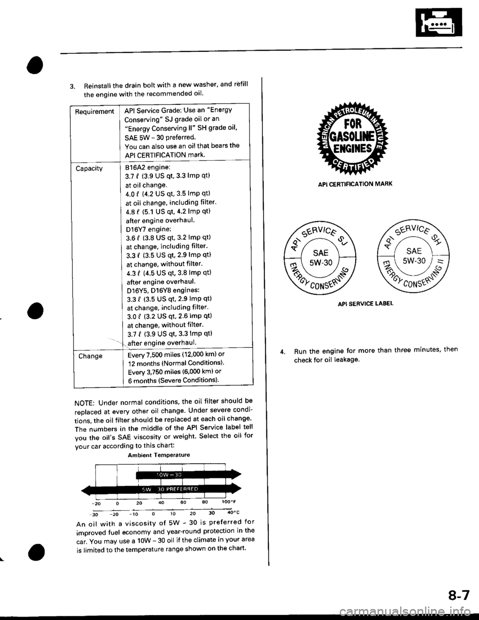
RequirementAPI Service Grade: Use an "Energy
Conserving" SJ grade oil or an"Energy Conserving ll" SH grade oil,
SAE 5W - 30 preferred
You can also use an oil that bears the
API CERTIFICATION mark.
Capacity[atolz engine:
3.7 f (3.9 US qt,3.3 lmp qtl
I at oil change.
J 4.0 r 9.2 US qt, 3.5 lmp qtl
I at oil change, including filter'
| 4.8 f (5.1 Us qt,4.2 lmp qt)
I after engine overhaul
I Dl6Y7 engine:
3.6 f (3.8 US qt, 3.2 lmP qt)
I at change. including filter.
I 3.3 f (3.5 US qt,2.9 lmP qtl
I at change, without filter.
I 4.3 f (4.5 us qt,3.8 lmp qtl
I after engine overhaul.
J D16Y5, D16Y8 engines:
L 3.3 { {3.5 US qt,2.9 lmp qt}
I at change, including filter.
3.01 (3.2 US qt,2.6lmp qt)
I at change, withoutfilter.
3.7 { (3.9 US qt,3.3 lmp qt}- '1.€fter engine overhaul.
ChangeEvery 7,500 miles (12,000 km) or
12 months (Normal Conditions).
Every 3,750 miles (6,000 kml or
6 months (Severe Conditions).
3. Reinstall the drain bolt with a new washer. and rbfill
the engine with the recommended oil.
NOTE: Under normal conditions, the oil filter should be
replaced at every other oil change Under severe condi-
tions, the oilfilter should be replaced at each oil change'
The numbers in the middle of the API Service label tell
you the oil's SAE viscosity or weight Select the oil for
vour car according to this chart:
30 20 -10 010 20 30 4OoC
An oil with a viscosity of 5W - 30 is preferred for
improved tuel economy and year-round protection in the
car. You may use a 10W - 30 oil if the climate in your area
is limited to the temperature range shown on the chart'
Ambient Temoerature
API CERTIFICATION MARK
API SERVICE LABEL
Run the engine tor more than three minutes, then
check for oii leakage
8-7
Page 239 of 2189
4.
Removal/lnspection/lnstallation
2.
3.
1.
5.
6.
1.
8.
Drain the engine oil.
Turn the crankshaft and align the white groove on
the crankshaft pulley with the pointer on the lower
cover.
Remove the cylinder head cover and upper cover'
Remove the power steering pump belt, air condi-
tioner beit and the alternator belt
Remove the crankshaft pulley and remove the lower
cover.
Remove the timing belt.
Remove the drive pulley.
Remove the oil pan and oil screen.
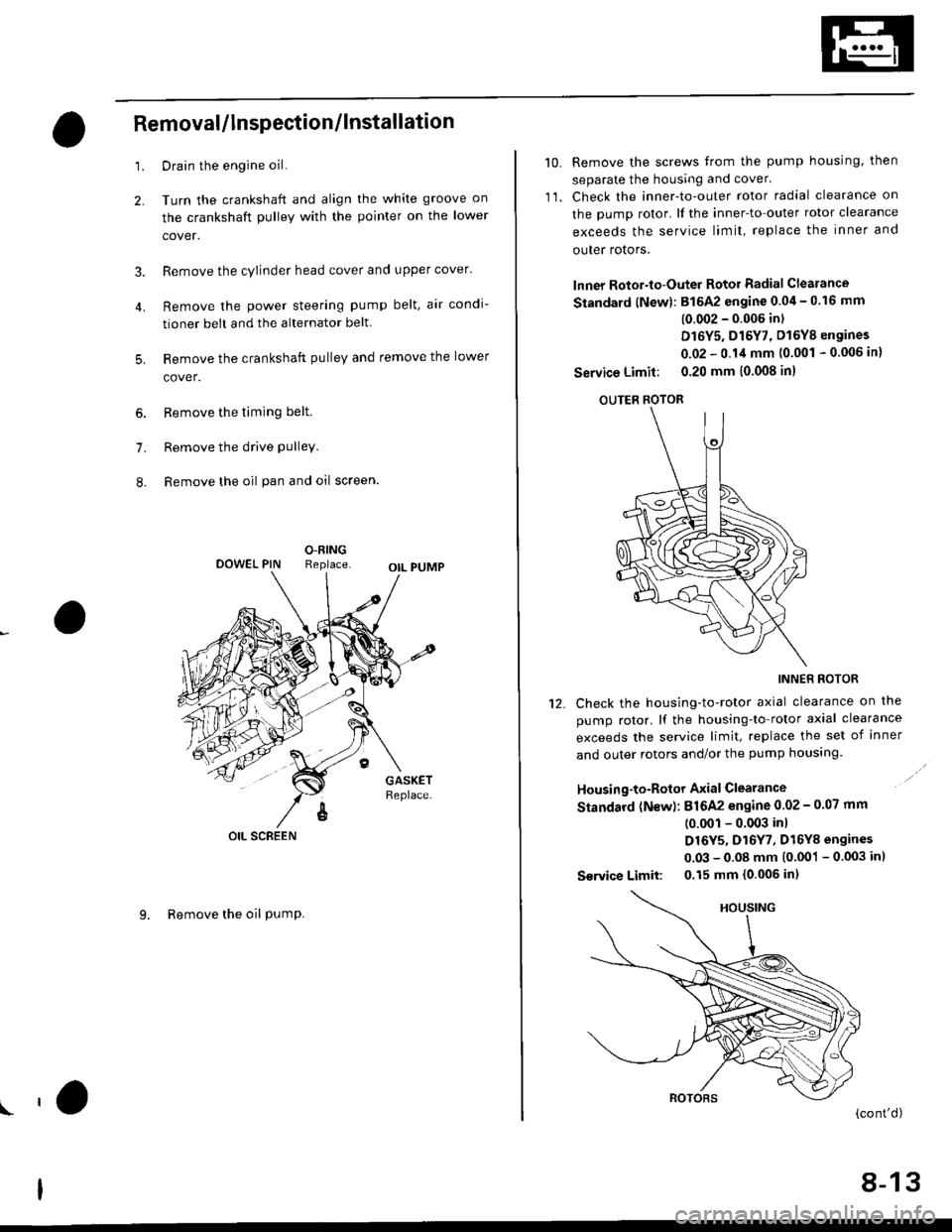
O.RINGReplaceOOWEL PIN
OIL SCREEN
9. Remove the oil PumP.
!'a
10.Remove the screws from the pump housing, then
separate the housing and cover'
Check the inner-to-outer rotor radial clearance on
the pump rotor. lf the inner-to outer rotor clearance
exceeds the service limit, replace the inner and
outer rotors.
lnner Rotor-to-Outer Rotor Radial Clearance
Standard {New}: 815A2 engine 0.04 - 0.16 mm
(0 002 - 0'006 in)
D16Y5, D16Y7, D16Y8 engines
0.02 - 0.14 mm 10.001 - 0.006 in)
Service Limit: 0.20 mm (0 008 inl
OUTER ROTOR
INNER ROTOR
Check the housing-to-rotor axial clearance on the
pump rotor. lf the housing-to rotor axial clearance
exceeds the service limit, replace the set of inner
and outer rotors and/or the pump housing
Housing-to-Rotor Axial Clearance
Standard (N€w): 816A2 engine 0.02 - 0.07 mm
(0.001 - 0.003 inl
D16Y5, D16Y7, D16Y8 engines
0.03 - 0.08 mm (0.001 - 0.003 inl
S€rvice Limit: 0.15 mm 10.006 in)
11.
't2.
(cont'd)
8-13
Page 240 of 2189
Oil Pump
RemovaUlnspection/lnstallation (cont'dl
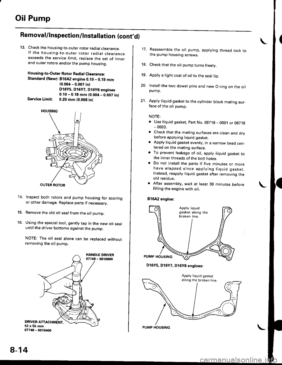
13. Check the housing-to-outer rotor radial clearance.lf the housing-to-outer rotor radial clearanceexceeds the service limit, replace the set of innerand outer rotors and/or the pump housing.
Housing-to-Outer Rotor Badial Clearanco:Standard {Newl: 816A2 sngine 0.10 - 0.19 mm(0.004 - 0.007 in)
D16y5, Di6y7, Dt6y8 engines0.10 - 0.18 mm {0.00it _ 0.007 in)Service Limit: 0.20 mm (0.008 in)
lnspect both rotors and pump housing for scoringor other damage. Replace parts if necessary.
Remove the old oil sealfrom the oil pump.
Using the special tool, gently tap in the new oil sealuntil the driver bottoms against the pump.
NOTE: The oil seal alone can be replaced withoutremoving the oil pump.
DRIVER ATT52x55mm077a6 - 0010ao0
14.
15.
16.
8-14
PUMP HOUSING
17. Reassemble the oil pump, applying thread lock tothe pump housing screws.
18. Check that the oil pump turns freely.
19. Apply a light coat of oilto the seal lip.
20. Install the two dowel pins and new O-ring on the oilpump.
21. Apply liquid gasket to the cylinder block mating sur_face of the oil pump.
NOTE:
. Use liquid gasket, Part No.08718 - oOOj or 08718- 0003.. Check that the mating surfaces are clean and drybefore applying liquid gaskel. Apply liquid gasket evenly, in a narrow bead cen-tered on the mating surface.o To prevent leakage of oil, apply liquid gasket tothe inner threads of the bolt holes.. Do not install the parts if five mtnures or morehave elapsed since applying liquid gasket.Instead. reapply liquid gasket after removing theold residue.
. After assembly, wait at least 30 minutes beforefilling the engine with oil.
81642 engine:
\
D16Y5, D16Y7, D16Y8 engines:
along the broken line.
Page 359 of 2189
Troubleshooting
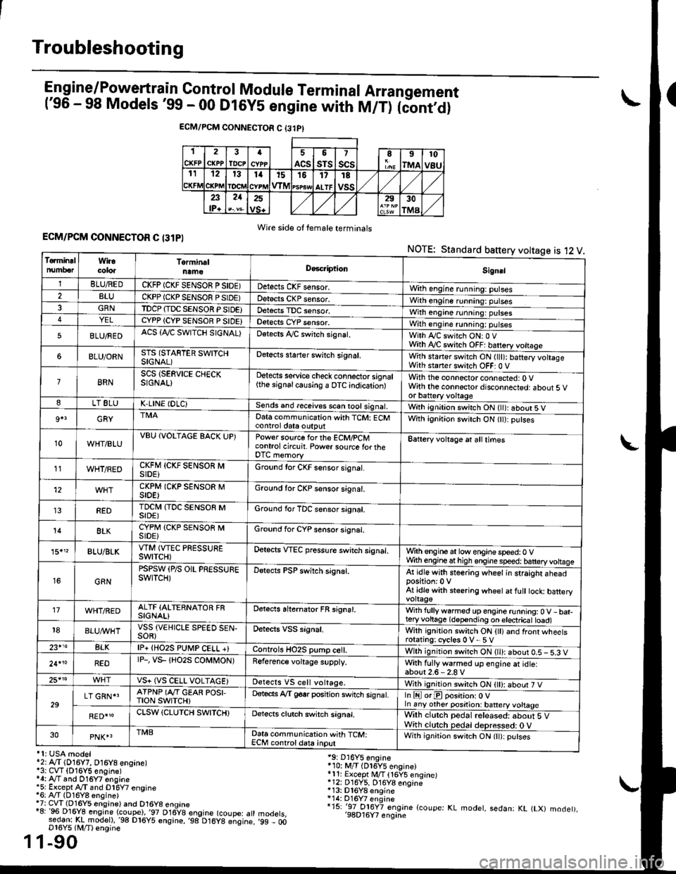
Engine/P_o_wgrtrain Control Module Terminal Arrangement('96 - 98 Models '99 - 00 Dt6y5 engine with M/T) tc'oniOi
ECM/PCM CONNECTOR C {31PI
1
CKFP
2
CXPPTDCPa
ACS
5
sTs
7
scsII
rMA
10
v8u121314t51517
ALTF
TE
vss23lP+
21252930
TMA
Wire side of female terminalsECM/PCM CONNECTOR C (31PI
NOTE: Standard baftery voltage is 12 V
'1: USA modelr2rA,.T (D16Y7, O16Y8 ensane)*3: CVT (O16Y5 engine)*4: Ay'T and O16Y7 engine'5: Excepl A./T snd Dl6Y7 engine16: Ay'T (D16Y8 ensine){7: CVT (Dl6Y5 eosine) and O16Y8 enoine"8: 96 Dl6Y8 engine (coupe),'97 D16y8 engine (coupe: atl:ed-9I t!!rnodelr,'98 D16y5 ensine,,98 D16y8 e;sine.D16Y5 lM/T) ensine
1-90
19: D16Y5 engine'10: M/T (Dl6Y5 engine)*11r Except M/T 116Y5 engine)*12: D16Y5, D16Y8 engine*13: Dl6Y8 enqine*14: O16Y7 enginei15: '-97 O16Y7 engjne (coupe: KL modet, sedan: KL (LX) modet),'98D16Y7 enqine'99 - 00
1
To.min!lnumberWiracoloaTorminalnameDo6criptlonSignal
1BLU/REDCKFP (CKF SENSOR P SIDE)Detects CKF sensor.With engine running: pulses2BLUCKPP (CKP SENSOF PSIDE)Detects CKP sensor.With engine running: pulses3GRNTDCP {TDC SENSOR PSIDE}Detects TDC sensor,With engine running: putses4YELCYPP (CYP SENSOR P SIDE)Detects CYP sensor.With engine running: pulses
5BLU/FEDACS {Tr'C SWITCH SIGNAL)Detects ,ay'C sw;tch signat.With Iy'C switch ONr 0 VWith Ay'C switch OFF: batrery vottage
6BLU/ORNSTS (STARTER SWITCHSIGNAL)Detects staner swilch signal,With staner switch ON ltlt): batery vohageWith staner switch OFF: 0 V
8RNSCS (SERVICE CHECKSIGNAL)Detects service check connector signal{the signalcausing a OTC indicationlWith the connector connected: O Vwith the connector disconnected: about 5 vor battery voltageLT 8LUK,LINE (DLC)Sends and receives scan iool signal,Wirh ignition switch ON { ): about 5 V
9+3GRYDat6 communication with TCM: ECMcontrol ctat6 outputWith ignition switch ON (tt):putses
10WHT/BLUVBU (VOLTAGE BACK UP)Power source forthe ECM/PCMcontrol circuit. Power sourc€ lortheDTC memory
Battery voltage at all times
11WHT/REDCKFM {CKF SENSOR MSIDE)Ground tor CKF sensor signal.
12CKPM (CKP SENSOR MSIDE)Ground for CKP sensor s;gnat.
REDTDCI\4 (TDC SENSOR MSIDE)Ground for TDC sensor signal.
14BLKCYPM (CKP SENSOB MSIDE}Groond for CYP sensor signal.
15."BLU/BLKVTM (VTEC PRESSUREswtTcH)Oetscts VTEC pressure switch signal.Wrth engine at low enginespeed:0 VWth engineathigh engine speed: tatteryvoltase
16GRN
PSPSW (P/S OIL PRESSUREswtTcH)Detects PSP switch signal.At idle with steering wheel in straight aheadposition:0 VAt idle with stsering wheet at fult tock batteryvoltage'17WHT/REDALTF (ALTERNATOR FRSIGNAL)Detects ahernator FR signal.With fullyw6rmed up engine running:0 V- bat-teryvohage (depending on electricat toad)18BLUI/VHTVSS {VEHICLE SPEED SEN-SOR}Oetects VSS signal.Whh ignitjon switch ON {tt) and front wheetsrotating: cycles 0 V- 5 V23+14BLKlP+ {HO2S PUtr4P CELL +}Controls HO2S pump ce .With ignition switch ON (ll): abour 0.5 - 5.3 V
24.10REDrP-, vs- {Ho2s coMt oN)Reference voltage supply.With fullywarmed up engine et idle:about2.6-2.8 V25*roVS+ (VS CELL VOLTAGE)Detects VS cell voltage.With ignition switch ON t): abour 7 V
29LT GRN*'ATPNP (Ar'T GEAR POSI,TroN swrTcH)Deteds Ay'T g6srposhion switch signat.In E orE position: O Vln any other position: battery vottage
RED{roCLSW (CLUTCH SWITCH}Detects clutch switch signal,Wilh clutch pedal released: about 5 VWith clutch pedal deDressed: O V30PNK4TMBData communication with TCM:ECM controldata inputWith ignit;on switch ON (lt):putses
Page 503 of 2189
Fuel Supply System
Fuel Pressure Regulator
Te3ting
@ Do not smoke during the tast. Keep open
flamcs away from your work arsa.
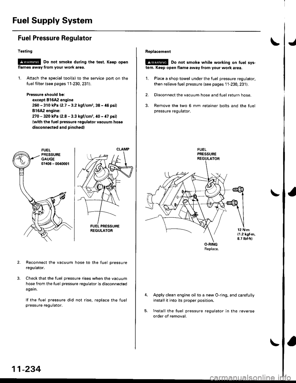
1. Attach the special tool(s) to the service port on the
fuel filter (see pages 1 1-230, 231).
Pressure should bo:
except 81642 engine
260 - 310 kPa |'2.7 - 3.2 kgllcrn2,38 - /t6 psil
816A2 engine:
27O - 320 kPa 12.8 - 3.3 kgf/cm,, 40 - 47 psi)
{with the tuel pressure regulator vacuum hose
disconnested and pinched)
Reconnect the vacuum hose to the fuel pressure
regulator.
Check that the fuel pressure rises when the vacuum
hose from the fuel pressure regulator is disconnected
again.
lf the fuel pressure did not rise, replace the fuel
pressure regutalor.
CLAMP
REGULATOR
11-234
Reolacement
@@ Do not smoke while working on luel sys-
tem. Keep open flame away from your work area,
1. Place a shop towel under the fuel pressure regulator,
then relieve fuel pressure (see pages 11-230,231l..
2. Disconnect the vacuum hose and fuel return hose.
3. Remove the two 6 mm retainer bolts and the fuel
pressure regurator.
Apply clean engine oil to a new O-ring. and carefully
install it into its proper position.
Install the fuel pressure regulator in the reverse
order of removal.