Part number HONDA CIVIC 1997 6.G User Guide
[x] Cancel search | Manufacturer: HONDA, Model Year: 1997, Model line: CIVIC, Model: HONDA CIVIC 1997 6.GPages: 2189, PDF Size: 69.39 MB
Page 848 of 2189
Differential
Oil Seal Installation/Side Clearance (cont'd)
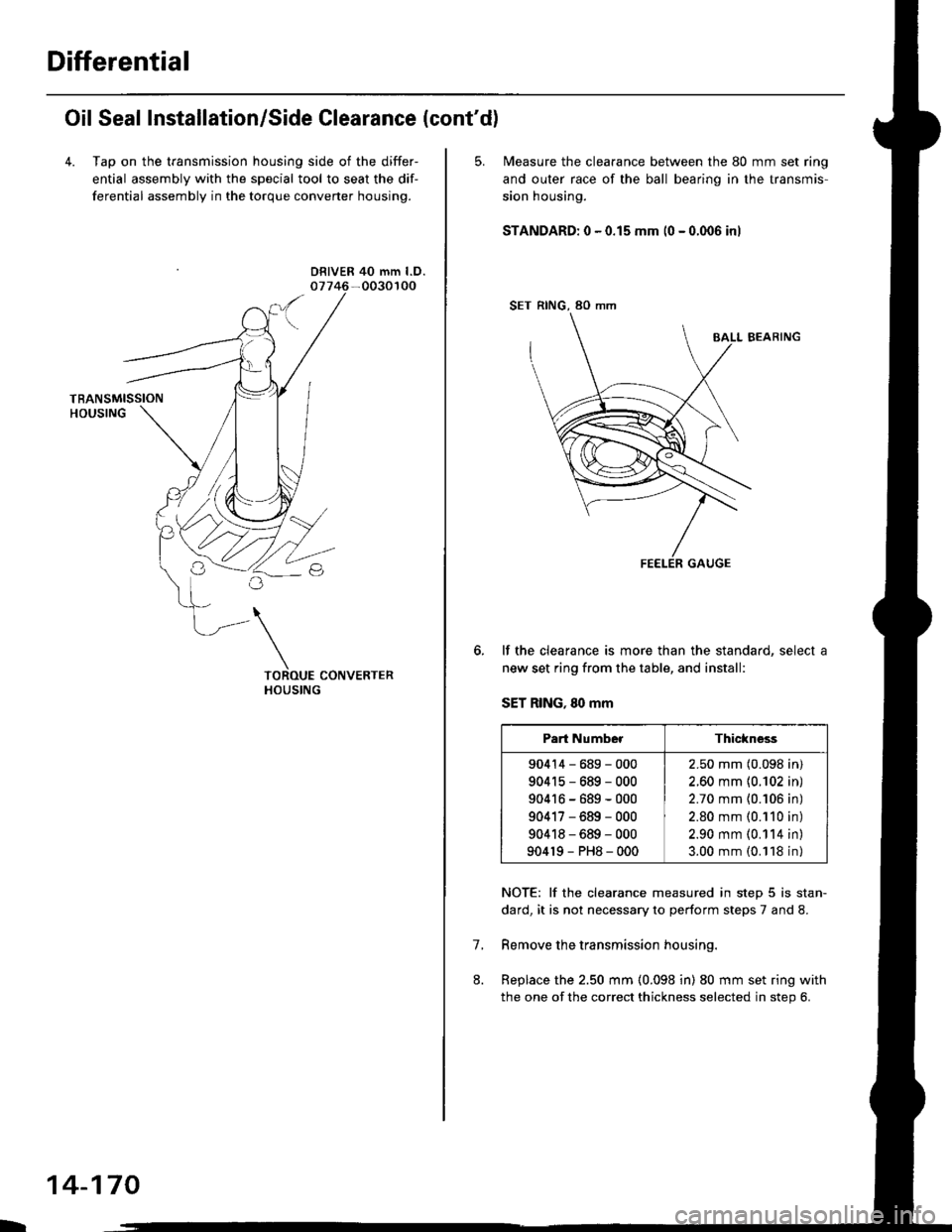
4. Tap on the transmission housing side of the differ-
ential assembly with the special tool to seat the dif-
ferential assembly in the torque converter housing.
DRIVER 40 mm l.D.
L
14-170
5. N4easure the clearance between the 80 mm set ring
and outer race of the ball bearino in the transmis-
sion housing.
STANDARD: 0 - 0.15 mm (0 - 0.006 inl
SET RING, 80 mm
BALL BEARING
lf the clearance is more than the standard, select a
new set ring from the table, and install:
SET RING, 80 mm
NOTE: lf the clearance measured in step 5 is stan-
dard, it is not necessary to perform steps 7 and 8.
Remove the transmission housing.
Replace the 2.50 mm (0.098 in) 80 mm set ring with
the one of the correct thickness selected in step 6.
7.
Part NumberThickness
90414-689-000
904r5-689-000
90416-689-000
90417-689-000
90418-689-000
904r9-PH8-000
2.50 mm (0.098 in)
2.60 mm {0.102 in)
2.70 mm {0.106 in)
2.80 mm (0.110 in)
2.90 mm (0.114 in)
3.00 mm (0.118 in)
Page 1004 of 2189
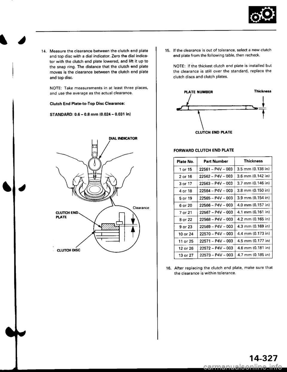
14. Measure the clearance between the clutch end plate
and toD disc with a dial indicator, Zero th€ dial indica-
tor with the clutch end plate lowered, and lift it up to
the snap ring. The distance that the clutch end plate
moves is the clearance between the clutch end plate
and toD disc.
NOTE: Take measurements in at least three places,
and use the average as the actual clearance.
Clutch End Plate-to-Top Disc Clesranc€:
STANDARD: 0.6 - 0.8 mm 10.024 - 0.031 inl
15. It the clearance is out of tolerance, select a new ciutch
end plate from the following table, then recheck.
NOIE: lf ihe thickest clutch end plate is installed but
the clearance is still over the standard, replace the
clutch discs and clutch Plates.
FORWARD CLUTCH END PLATE
After replacing the clutch end plate, make sure thal
the clearance is within tolerance.
16.
PTATE I{UMBEN
Plate No.Part NumberThickn€ss
1or1522561 - P4V - 0033.5 mm (0.138 in)
2or1622562 - P4V -OO33.6 mm (0.142 in)
3or1722563-P4V-0033.7 mm (0.146 in)
4or1822564 - P4V - 0033.8 mm (0.150 in)
5or192256s-P4V-0033.9 mm (0.154 in)
6ot2022566-P4V-0034.0 mm (0.157 in)
7 ot 2122567 -P4V -0034.1 mm (0.161 in)
8ot2222568-P4V-0034.2 mm (0.165 in)
9ot2322569-P4V-0034.3 mm {0.169 in)
10 or 2422570-P4V -OO34.4 mm (0.173 in)
'll or 2522571,P4V-0034.5 mm (0.177 in)
12 ot 2622572-P4V-OO34.6 mm (0.181 in)
13 ot 2722573-P4V -OO34.7 mm {0.185 in)
14-327
Page 1005 of 2189
Secondary Gear Shaft
25 x 35 mm Thrust Shim Selection
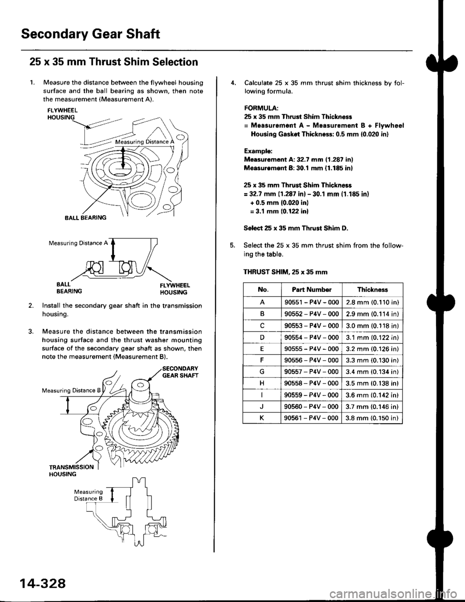
1. Measure the distance between the flywheel housing
surface and the ball bearing as shown, then note
the measurement (Measurement A).
FLYWHEELHOUSING
>dt?'
BALL BEARING
EALL FLYWHEELBEARING HOUSTNG
Install the secondary gear shatt in the transmission
housing.
Measure the distance between the transmission
housing surface and the thrust washer mounting
surface of the secondary gear shaft as shown, then
note the measurement (Measurement B).
O
Measuring Distance A
BALL
14-328
Calculate 25 x 35 mm thrust shim thickness bv fol-
lowing formula.
FORMULA;
25 x 35 mm Thrust Shim Thicknoss
= Measurement A - Measurement B + Flywheel
Housing Gasket Thickness: 0.5 mm {0.020 in}
Example:
Measurement A: 32.7 mm (1.287 in)
Moasurem.nt B: 30.! mm {1.185 in}
25 x 35 mm Thrust Shim Thickness
= 32.7 mm (1.287 in) - 30.1 mm (1.185 in)
+ 0.5 mm {0.020 in)
= 3.1 mm (0.122 inl
Select 25 x 35 mm Thrust Shim D.
Select the 25 x 35 mm thrust shim from the follow-
ing the table.
THRUST SHIM, 25 x 35 mm
No.Part NumberThickne3s
90551 - P4V - 0002.8 mm (0.110 in)
B90552-P4V-0002.9 mm (0.114 in)
c90553-P4V-0003.0 mm (0.118 in)
D90554-P4V-0003.1 mm (0.122 in)
E90555-P4V-0003.2 mm (0.126 in)
90556-P4V-0003.3 mm (0.130 in)
G90557-P4V-0003.4 mm (0.134 in)
H90558-P4V-0003.5 mm (0.138 in)
90559-P4V-0003.6 mm {0.142 in)
90560-P4V-0003.7 mm (0.146 in)
K90561 - P4V - 0003.8 mm (0.'150 in)
Page 1009 of 2189
Differential
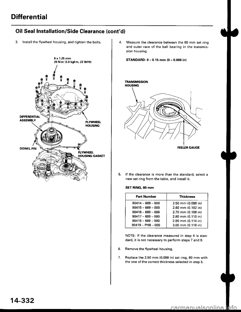
Oil Seal Installation/Side Clearance (cont'dl
3. Installthe flywheel housing, and tighten the bolts.
DOWEL PIN
1 .25 mmN m (3.0 kgt m,22 lbf.ttl8x29
uigE
14-332
4. Measure the clea.ance between the 80 mm set ring
and outer race of the ball bearing in the transmis-
sion housing.
STANDARD: 0 - 0.15 mm (0 - 0.006 in)
lf the clearance is more than the standard, select a
new set ring from the table, and install it.
SET RING, 80 mm
NOTE: lf the clearance measured in steD 4 is stan-
dard, it is not necessary to perform steps 7 and 8.
Remove the flywheel housing.
Replace ttle 2.50 mm (0.098 in) set ring, 80 mm with
the one ot the correct thickness selected in steD 5.
6.
7.
Part NumberThickness
904'�r4-689-000
90415-689-000
90416-689-000
90417-689-000
90418-689-000
90419-PH8-000
2.50 mm (0.098 in)
2.60 mm (0.102 in)
2.70 mm (0.106 in)
2.80 mm (0.110 in)
2.90 mm (0.114 in)
3.00 mm (0.118 in)
Page 1016 of 2189
Transmission
16.
Reassembly (cont'dl
21.
17.
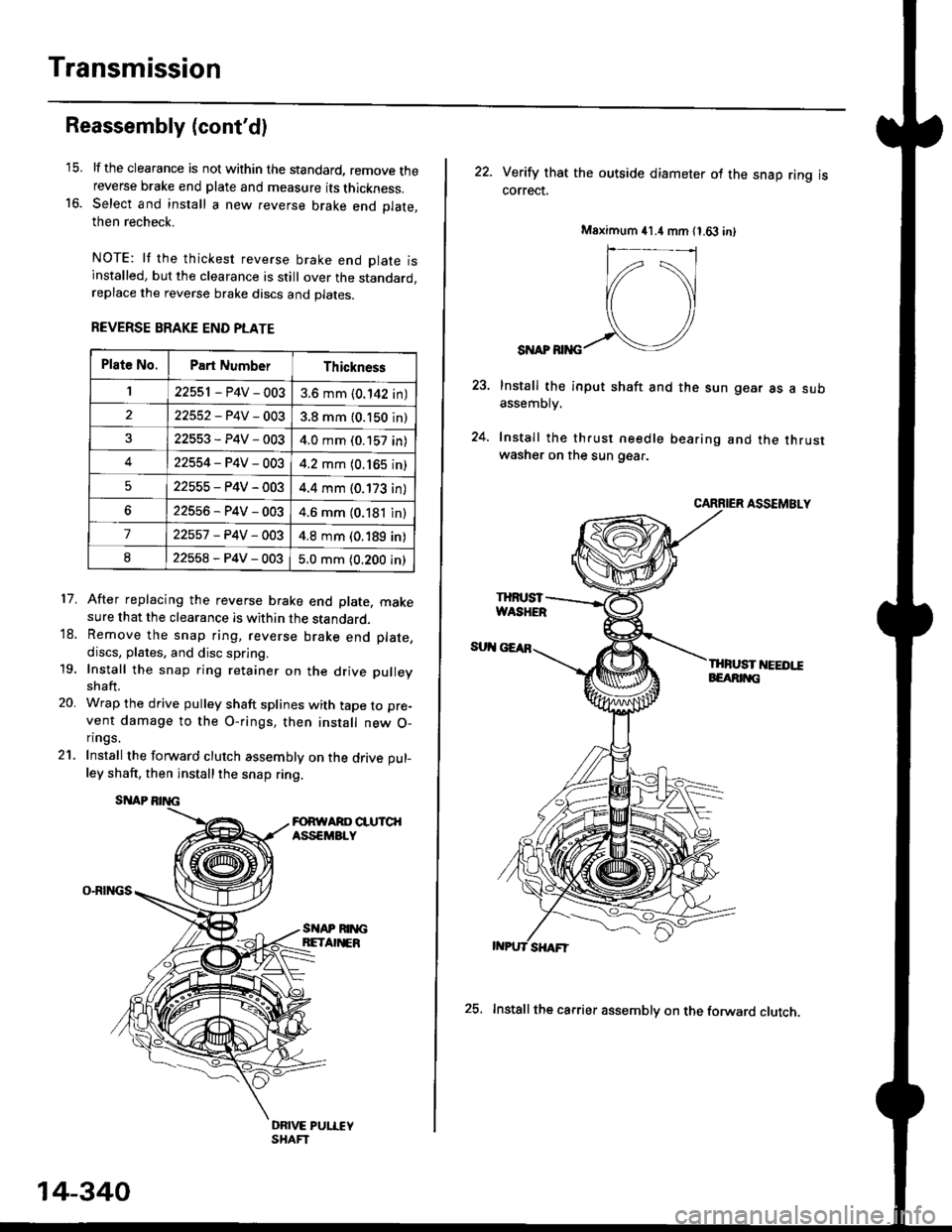
lf the clearance is not within the standard, remove thereverse brake end plate and measure its thickness.Select and install a new reverse brake end Dlate.then recheck.
NOTE: lf the thickest reverse brake end olate isinstalled, but the clearance is still over the standard,replace the reverse brake discs and plates.
REVERSE BRAKE END PLATE
After replacing the reverse brake end plate, makesure that the clearance is within the standard.Remove the snap ring, reverse brake end plate,
discs, plates. and disc spring.
Install the snap ring retainer on the drive pulley
shaft.
Wrap the drive pulley shaft splines with tape to pre-
vent damage to the O-rings, then install new O-n ngs.
Install the forward clutch assembly on the drive pul-
ley shaft, then installthe snap ring.
SITAP
O-RINGS
18.
19.
20.
SI{AP RIM;BETA EB
DRIVE PUI.IEYSHAFT
Plat6 No.Part NumberThickness
122551 - P4V - 0033.6 mm (0.142 in)
22552-P4V-0033.8 mm (0.150 in)
22553-P4V-0034.0 mm (0.157 in)
422554-P4V-0034.2 mm (0.165 in)
522555-P4V-0034.4 mm (0.173 in)
622556-P4V-0034.6 mm (0.181 in)
722557 -P4V -OO34.8 mm (0.189 in)
822558-P4V-0035.0 mm (0.200 in)
14-340
25. Installthe carrier assembly on the forward clutch.
22. Verity that the outside diameter ol the snap ring iscorrect.
SI{AP RIiIG
Install the input shaft and the sun gear as a subassemDry.
Install the th.ust needle bearing and the thrustwasher on the sun gear.
CARRIER ASSEMBLY
THFUST I'IEEDI!EEARIT{G
Msximum 41.4 mm 11.63 in)
IHruST
Page 1019 of 2189
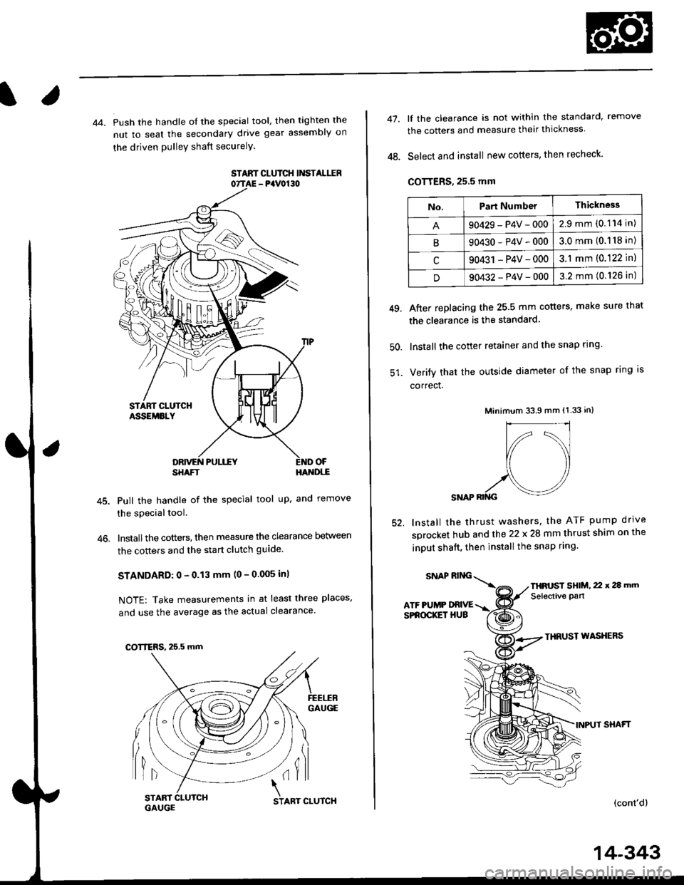
44. Push the handle of the special tool, then tighten the
nut to seal the secondary drive gear assembly on
the driven pulleY shaft securelY.
STAAT CLUTCH Ii'ISTALIIR07TAE - PaV0130
OF
46.
SHAFTHA'{DI,-E
Pull the handle of the special tool up, and remove
the special tool.
lnstallthe cotters, then measure the clearance Delween
the cotters and the start clutch guide
STANDARD: 0 - 0.13 mm (0 - 0.005 inl
NOTE: Take measurements in at least three places,
and use the average as the actual clearance
GAUGE
lil(il
COTTERS, 25.5 mm
START 1
GAUGCSTART CLUTCH
14-343
47.
48.
lf the clearance is not within the standard, remove
the cotters and measure their thickness
Select and install new cotters, then recheck.
COTTERS, 25.5 mm
After replacing the 25.5 mm cotters, make sure that
the clearance is the standard
lnstall the cotter retainer and the snap rlng
Verify that the outside diameter of the snap ring is
correct.
Minimum 33.9 mm (1.33 in)
SNAP RII{G
lnstall the thrust washers. the ATF pump drrve
sprocket hub and the 22 x 28 mm thrust shim on the
inDUt shaft, then install the snap ring.
49.
50.
52.
THRUST WASXERS
INPUT SHAFT
(cont'd)
No.Part NumberThickness
90429-P4V-0002.9mm(0.114 in)
B90430-P4V-0003.0mm(0.118 in)
c90431 -P4V-0003.1 mm (0.122 ln)
D90432-P4V-0003.2 mm (0.126 in)
SNAPRING\
ATF PUMP DRIVESPROCKET HUB
THFUST SHIM, 22 x 2a mm
Selective pan
Page 1256 of 2189
Windshield, Rear Window and Ouarter Glass
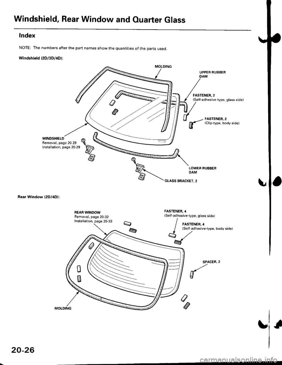
Index
NOTE: The numbers after the part names show the quantities of the parts used.
Windshield l2Dl3D/4D):
WINDSHIELDRemoval, page 20 28Installation, page 20-29
Rear Window (2Dl4Dl:
UPPER RUBBERDAM
FASTENER, 2(Sell-adhesive type, glass side)
FASTENER, 2lClip-type, body side)
FASTENER, 4(Self-adhesive-type, glass side)
/ FASTENER,4
/ lSelf adhesive-type, body sidel
*,/
M
SPACER,
w
/>
@
20-26
Page 1260 of 2189
Windshield
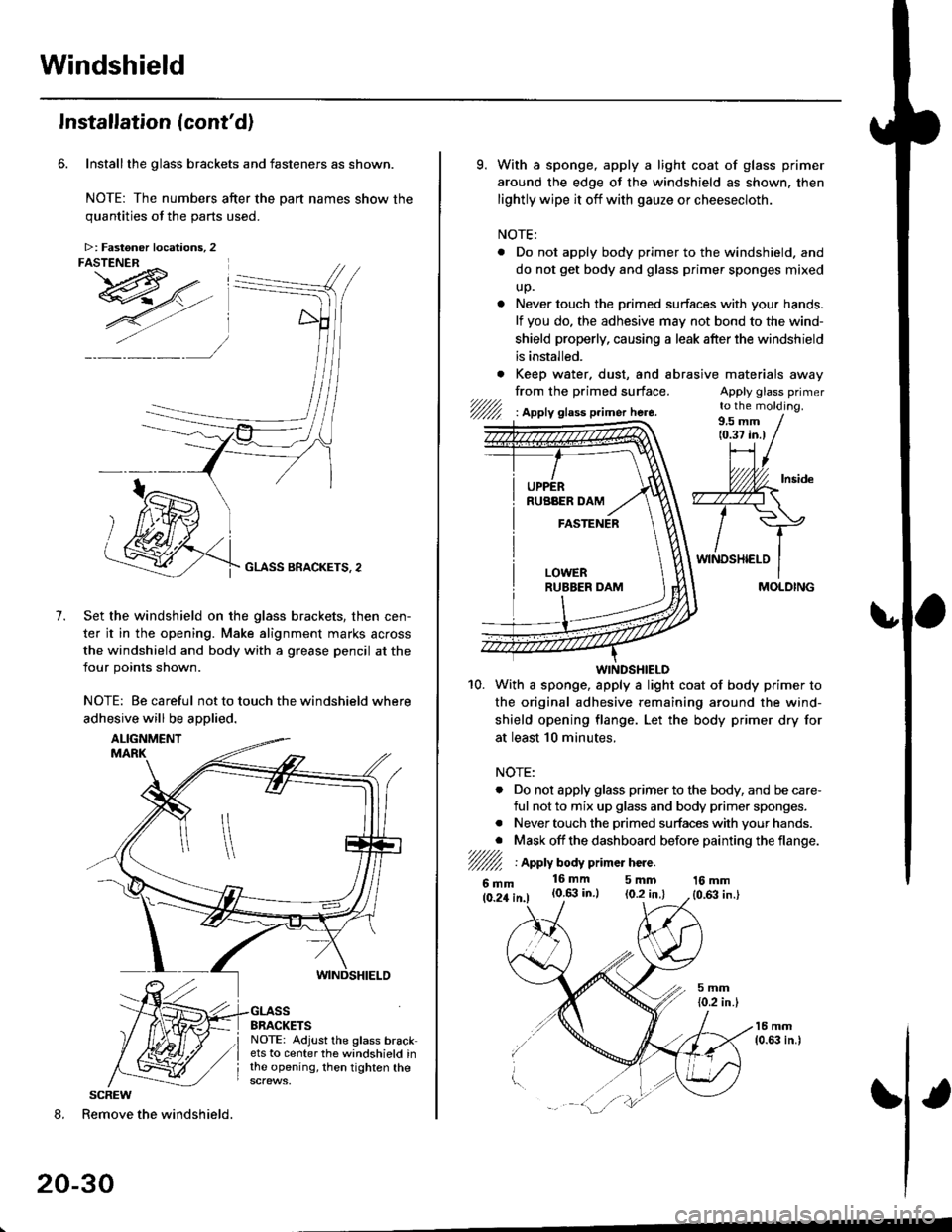
Installation (cont'd)
Installthe glass brackets and fasteners as shown.
NOTE: The numbers after the part names show thequantities of the oarts used.
GLASS BRACKETS, 2
Set the windshield on the glass brackets, then cen-
ter it in the opening. Make alignment marks across
the windshield and body with a grease pencil at the
four points shown.
NOTE: Be careful not to touch the windshield where
adhesive will be aDolied.
7.
8. Remove the windshield.
20-30
>: Fastoner locations, 2FASTENER ^ I
I
SCREW
9. With a sponge, apply a light coat of glass primer
around the edge of the windshield as shown. then
lightly wipe it off with gauze or cheesecloth.
NOTE:
. Do not apply body primer to the windshield. and
do not get body and glass primer sponges mixed
up.
. Never touch the primed surfaces with your hands.
lf you do. the adhesive may not bond to the wind-
shield properly, causing a leak after the windshield
is installed.
. Keep water. dust, and abrasrve
from the primed surface.t/////,'/////l I Apply glass p.imer here.
materaals away
Apply glass primerto the molding.
WINDSHIELD
10. With a sponge. apply a light coat of body primer to
the original adhesive remaining around the wind-
shield opening flange. Let the body primer dry for
at least 10 minutes.
NOTE:
. Do not apply glass primer to the body, and be care-
ful not to mix up glass and body primer sponges.
. Never touch the primed surfaces with your hands.
. Mask off the dashboard before painting the flange.7////l/////l I Apply body p mer hcre.
6mm16mm 5mm(0.6:| in.) (0.2 in.l16 mm
{0,63 in.}
/
MOLDING
Page 1297 of 2189
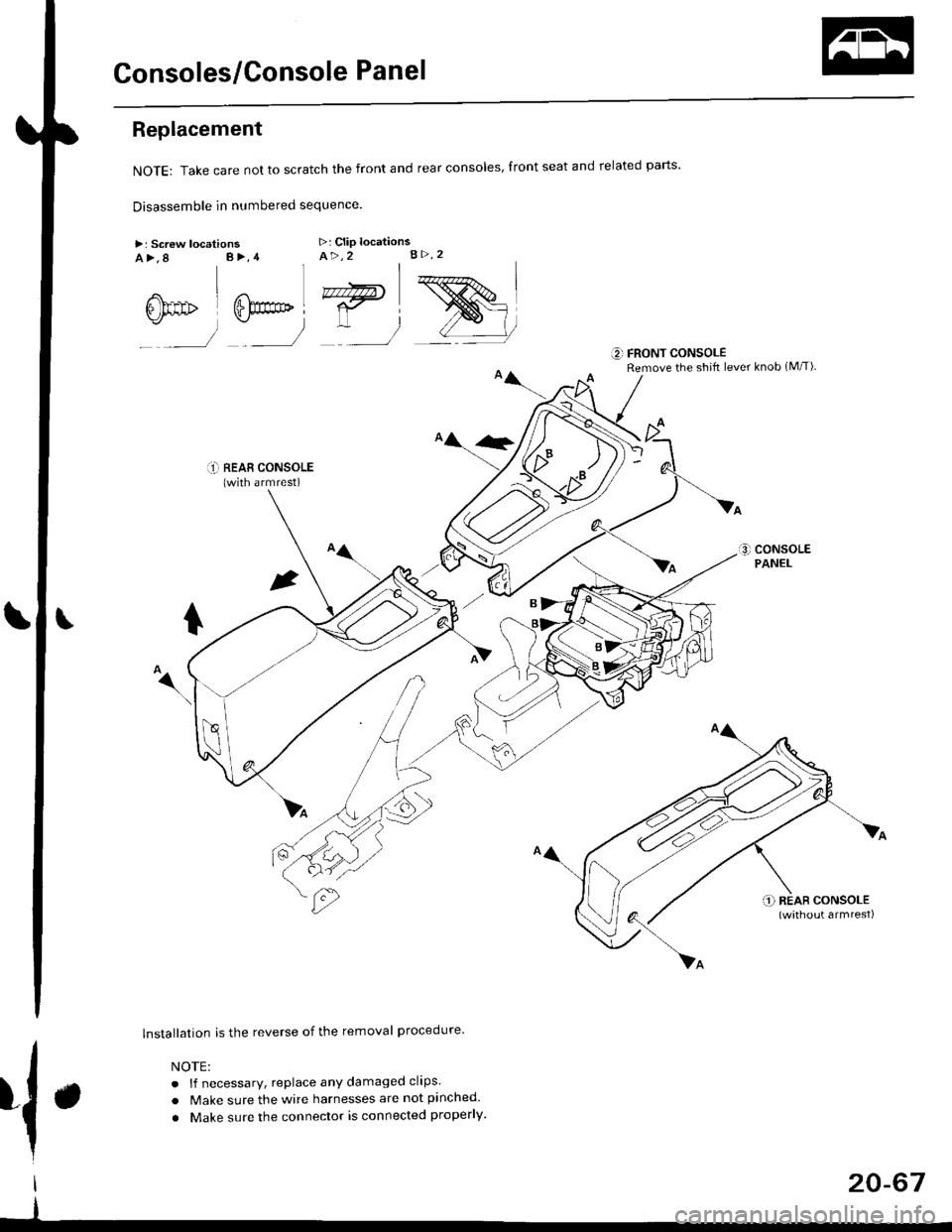
Consoles/Console Panel
Replacement
NoTE:Takecarenottoscratchthefrontandrealconso|es,frontseatandre|atedparts.
Disassemble in numbered sequence
>: Screw locationsa>,8 B>,4>: Clip locationsA>,2 B>.2
' nnffir
:__)
"=)
:)
::r_l REAB CONSoLE(with armrest)
lnstallation is the reverse of the removal procedure
NOTE:
. lf necessary, replace any damaged clips.
. Make sure the wire harnesses are not pinched.
. Make sure the connector is connected properly.
€] FRONT CONSOLERemove the shift lever knob (M/T)
{.
I
I
20-67
Page 1353 of 2189
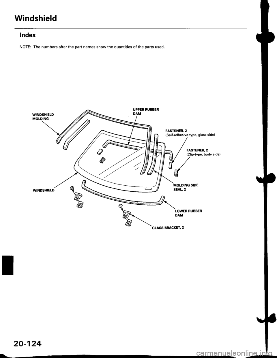
Windshield
lndex
NOTE: The numbers after the part names show the quantities of the parts used.
wlNDSHIELDMOLDING
UPPER RUBBERDAM
FASTENER, 2(Self-adhesive-type, glass side)
FASTENER, 2{Clip-type, body sido)
WINDSHIELD
20-124
L-..-