Connectors HONDA CIVIC 1997 6.G Owner's Manual
[x] Cancel search | Manufacturer: HONDA, Model Year: 1997, Model line: CIVIC, Model: HONDA CIVIC 1997 6.GPages: 2189, PDF Size: 69.39 MB
Page 347 of 2189
![HONDA CIVIC 1997 6.G Owners Manual System Description
System Connectors lDash and Floor] (contdl
(99 - 00 mod€ls oxc€pt Dl6Y5 ongine with M/T)
11-78 HONDA CIVIC 1997 6.G Owners Manual System Description
System Connectors lDash and Floor] (contdl
(99 - 00 mod€ls oxc€pt Dl6Y5 ongine with M/T)
11-78](/img/13/6068/w960_6068-346.png)
System Description
System Connectors lDash and Floor] (cont'dl
('99 - 00 mod€ls oxc€pt Dl6Y5 ongine with M/T)
11-78
Page 349 of 2189
![HONDA CIVIC 1997 6.G Owners Manual System Descriptions
System Connectors lFuel Pump]
(9!, - 00 models 6xcept Dl6Y5 ongino with M/T)
\(
I
c568
ffi
c565
E
c792
Different wires with the same color have been given a number suffix to disti HONDA CIVIC 1997 6.G Owners Manual System Descriptions
System Connectors lFuel Pump]
(9!, - 00 models 6xcept Dl6Y5 ongino with M/T)
\(
I
c568
ffi
c565
E
c792
Different wires with the same color have been given a number suffix to disti](/img/13/6068/w960_6068-348.png)
System Descriptions
System Connectors lFuel Pump]
('9!, - 00 models 6xcept Dl6Y5 ongino with M/T)
\(
I
c568
ffi
c565
E
c792
Different wires with the same color have been given a number suffix to distinguish them (for example, YEUBLKIand YEVBLK, are not the same).
O: Related to Fuel and Emissions System.- Connector with male terminals (double outline): View from terminal side- Connector with female terminals (single outline): View from wire side
c793
fr
NOTE: o
a
a
1 1-80
Page 352 of 2189
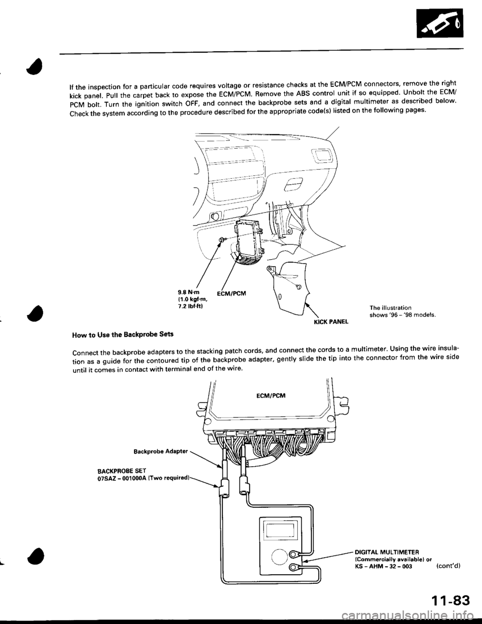
lf the inspection for a particular code requires voltage or resistance checks at the ECM/PCM connectors, remove the right
kick panel. Pull the carpet back to expose the ECM/PCM. Remove the ABS control unit if so equipped. unbolt the EcM/
PCM bolt. Turn the ignition switch oFF, and connect the backprobe sets and a digital multimeter as described below
check the system according to the procedure described for the appropriate code(s) listed on the following pages'
The illustrationshows '96 - '98 models.
How to Use lhe Backprobe Sets
connect the backprobe adapters to the stacking patch cords, and connect the cords to a multimeter. using the wire insula-
tion as a guide for the contoured trp of the backprobe adapter. gently slide the tip into the connector from the wire side
until it comes in contact with terminal end of the wire'
BackProbe
BACKPROEE SET
07SAZ - 001000A lTwo
DIGITAL MULTIMETER(Commercially avail.bleI orKs - AHM - 32 - oo3 (cont'd)
KICK PANEL
1 1-83
Page 353 of 2189
Troubleshooting
Troubleshooting Procedures (cont,dl
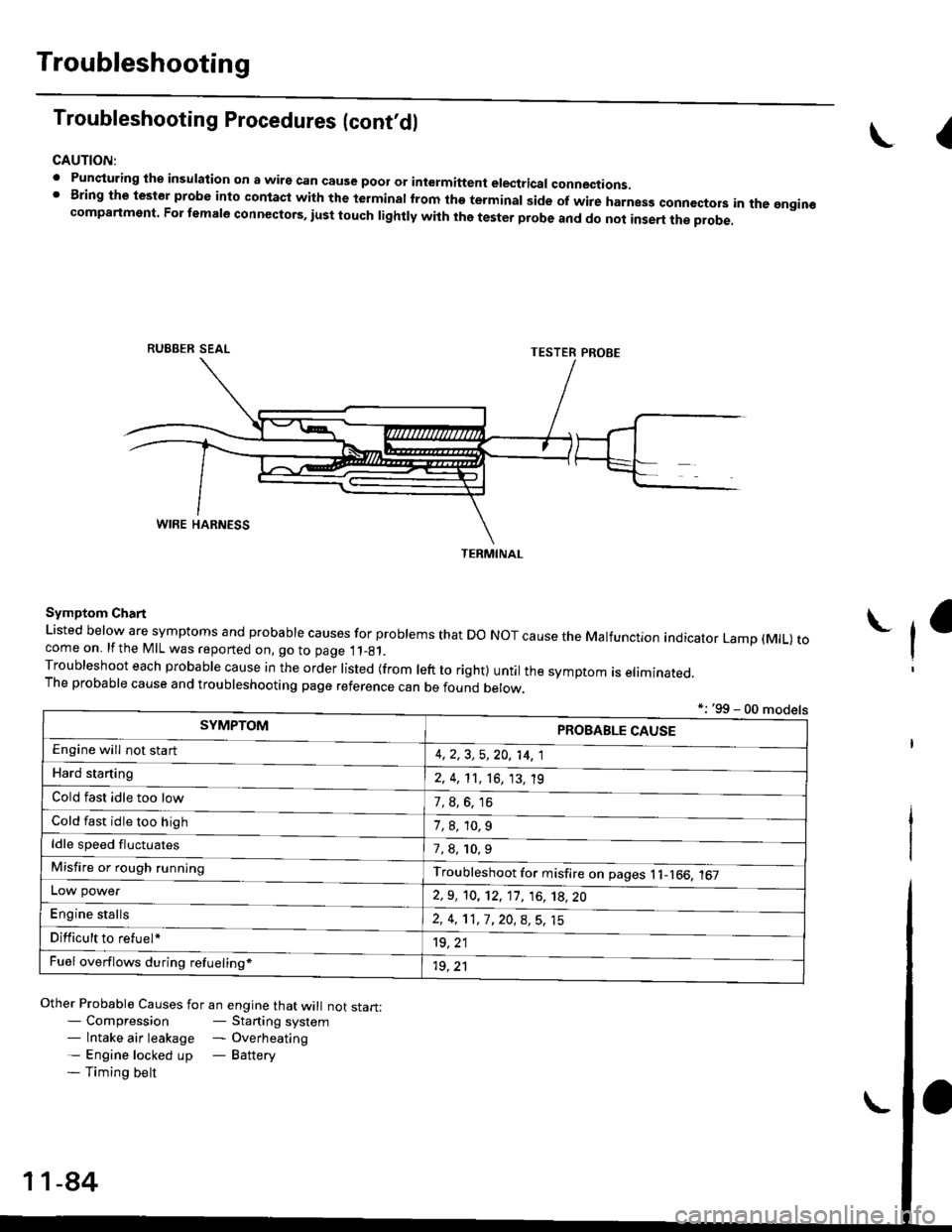
CAUTION:
. Punqturing ihe insulation on a wirs can cause poor or intermiftent electricar connections.I Bring the test€r probe into contacl with the terminatlrom the terminal side of wire harnesg conncctors in the gngin€compartment. For temale connectors, iust touch lightly with the tester probe and do not inse.t the probe.
\I
RUBBER SEAL
Other Probable Causes for an engine that will not start:- Compression- Starting system- lntake air leakage - Overheating- Engine locked up - Battery- Timing belt
TESTER PROBE
Symptom Chart
Listed below are symptoms and probable causes for problems that Do NoT cause the Malfunction indicator Lamp (MlL) tocome on. lfthe MIL was reported on, go to page 11_81.Troubleshoot each probabre cause in the order risted (from reft to right) untir the symptom is eriminated.The probable cause and troubleshooting page reference can be found berow.
L
*: '99 - 00 models
TERMINAL
SYMPTOMPROBABLE CAUSE
4,2,3, 5,20, 14, 1
2, 4, 11, 16, 13, 't9
?, s^6. 16
1,8,10.9
Engine will not sta rt
Hard starting
Cold fast idle too low
Cold fast idle too high
ldle speed fluctuates7,8, 10.9
Troubleshoot for misfire on pages l1-166, 167Misfire or rough running
LOW power
E"g|* "t"lb
2,9, 10, 12, 11, 16, 't8,20
2,4,11,7,20,8,5,15
't9, 21
1r, ,1
Difficult to refuel*
Fuel overflows during refueling*
11-84
Page 372 of 2189
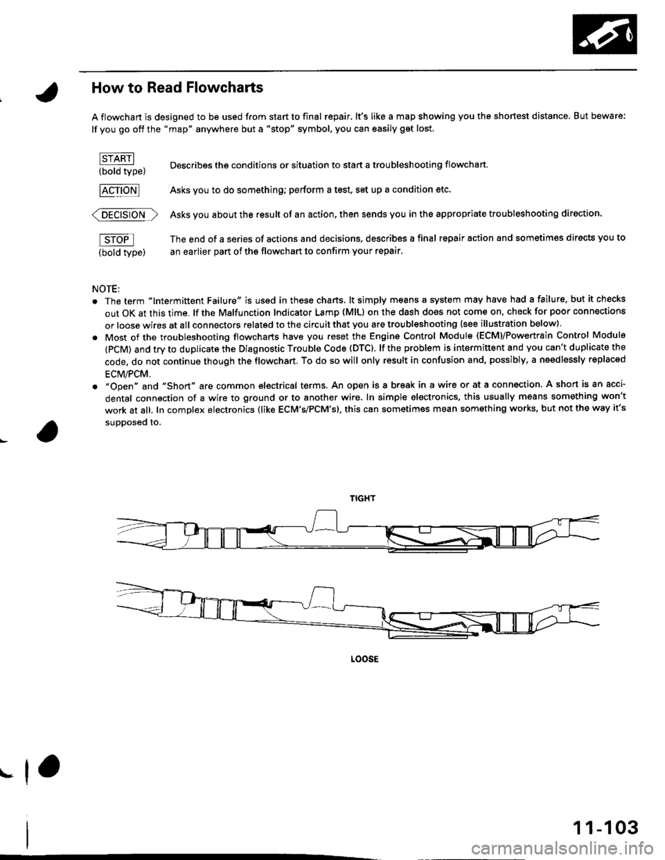
How to Read Flowcharts
A flowchart is designed to be used from start to final repair. lt's like a map showing you the shortest distance. But beware:
lf you go off the "map" anywhere but a "stop" symbol, you can easily get lost.
tSrARTl(bold type)
FanoNl
@
tsroP I
{bold type)
Describes the conditions or situation to start a troubleshooting flowchart.
Asks you to do something; perform a test, set up a condition etc.
Asks you about the result of an action, then sends you in the appropriate troubleshooting direction.
The end of a series of actions and decisions. describes a final repair action and sometimes directs you to
an earlier part of the flowchart to confirm your repair,
NOTE:
. The term "lntermittent Failure" is used in these charts, lt simply means a system may have had a failure. but it checks
out OK at this time. lf the Malfunction Indicator Lamp (MlL) on the dash does not come on, check for poor connections
or loose wires at all connectors related to the circuit that you are troubleshooting (see illustration below)'
. Most of the troubleshooting flowcharts have you reset the Engine Control Moduls (ECM)/Powertrain Control Module
(pCM) and try to duplicate the Diagnostic Trouble Code (DTC). lf the problem is intermittent and you can't duplicate the
code, do not continue though the flowchart. To do so will only result in confusion and, possibly, a needlessly replaced
ECM/PCM.
. ,,Open" and "Short" are common electrical terms. An open is a break in a wire or at a connection. A short is an acci-
dental connection of a wire to ground or to another wire. In simple electronics, this usually means something won't
work at all. In complex electronics (like ECM's/PCM'sl. this can sometim€s mean something works, but not the way it's
suDDosed to.
toosE
1 1-103
Page 379 of 2189
PGM-FI System
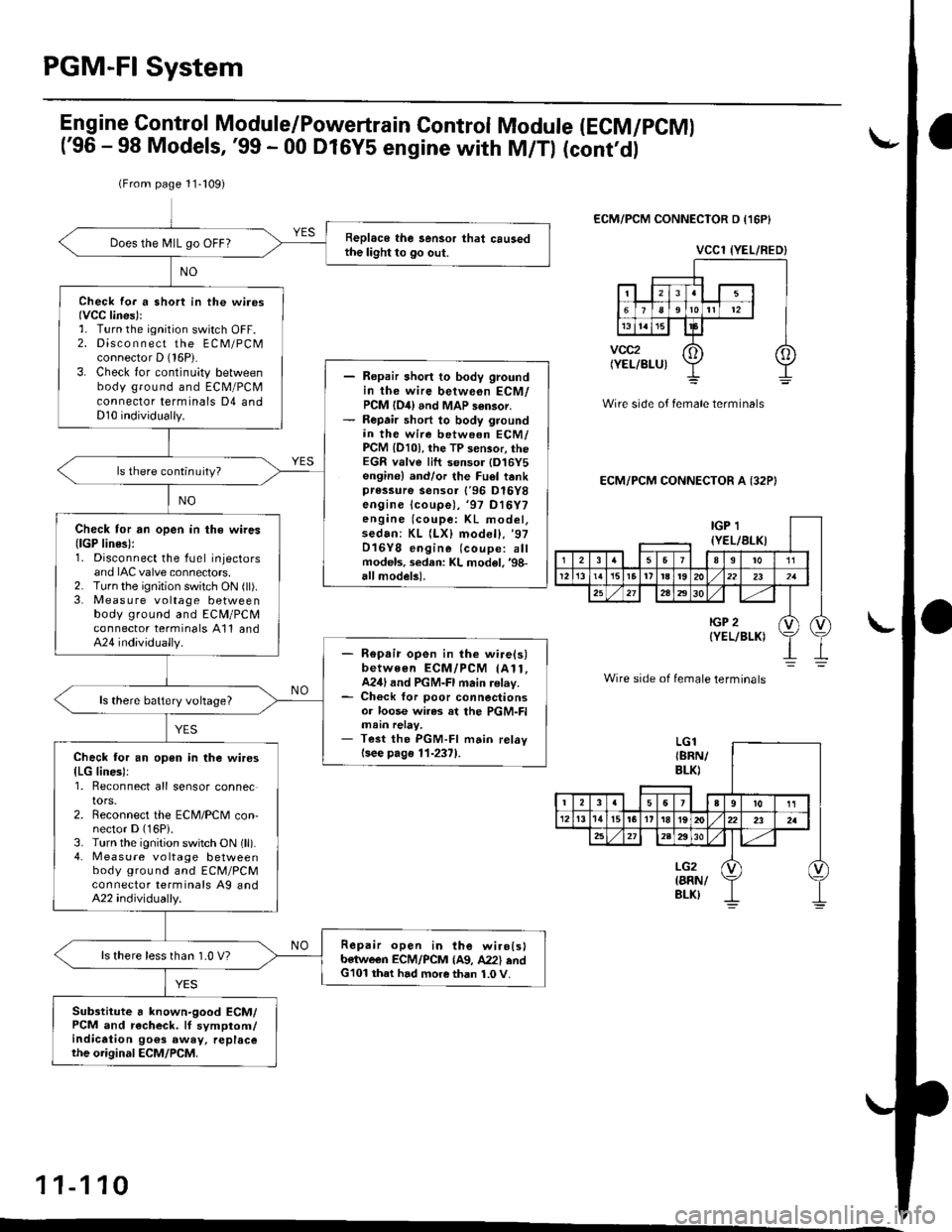
(From page 11-109)
Replace the sensor that causedthe light to go out.Does the N4lL go OFF?
Check fo. a short in the wi.os(VCC lines):':. Turn the ignition switch OFF.2. Disco n n ect the ECM/PCMconnector D (16P).
3. Check for continuity betweenbody ground and ECM/PCMconnector terminals D4 andD10 individually.
Ropair short to body groundin the wire betweon ECM/PCM {O4) and MAP s6n3or.Repair short to body groundin the wire between ECM/PCM lD10l, the TP sensor, theEGR valve lift sensor {D16Y5engine) and/or the Fuel tankpressure sensor {'96 Dl6Ygengine lcoupe),'97 D16Y7engine (coupe: KL model,sedan: KL (LXl model), '97
D16Y8 engine (coupe: allmodels, sedan: KL model. €8-allmodelsl.
ls there continuity?
Check tor rn open in the wires(lGP lines):1. Disconnect the fuel injectorsand IAC valve connectors,2. Turn the ignition switch ON (ll).3. Meas u re voltage betweenbody ground and ECM/PCMconnector terminals A11 and424 indivjdually.- Repair open in the wirels)between ECM/PCM (A11,A24land PGM-Fl main relay.- Check for poor connectionsor loose wiras at the PGM-FImain relay,- Test the PGM-FI mdin relavlsee pag6 11-237).
ls there battery vohage?
Check for an open in the wires(LG line3):1. Reconnect all sensor connectors.2. Reconnect the ECM/PCM con-nector D (16P).
3. Turn the ignition switch ON (ll).4. Measure vo ltage betweenbody ground and ECM/PCMconnector terminals Ag andA22 individually.
Repair open in the wirolglb€twe€n ECM/PCM {A9, A22} andG101 that had more than 1.0 V.
ls there less than 1.0 V?
Substitute 6 known-good ECM/PCM and r€check. lf symptom/indication 9o€s away, replacethe original ECM/PCM.
Engine Control Module/Powertrain Control Module (ECM/pCMl
('96 - 98 Models, '99 - 00 D16Y5 engine with M/Tl (cont,dl
ECM/PCM CONNECTOR D {16P}
Wire side of female terminals
ECM/PCM CONNECTOR A (32P}
Wire side of female terminals
11-110
LG1
VCCl {YEL/RED}
IGP 1{YEL/BLKI
2I11
1213l5t6Itt8t9202321
25272a2930
IGP 2(YEL/BLKIv) (l
{8RN/BLK)
I258tol1'12tt11t5l617t8t920232a
2A2330
LG2{8RN/8LK}
Page 381 of 2189
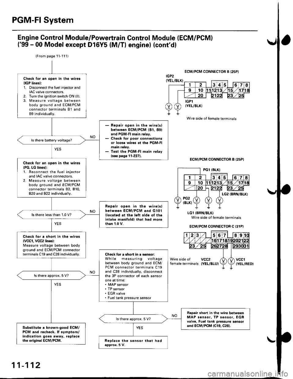
PGM-FI System
(From page'11-111)
Check loi an open in the wires(lGP linesl:1. Disconnect the lueliniector andIAC valve connectors.2. Turn the ignition switch ON (ll).
3, Measu re voltage betweenbody ground and ECM/PCMconnector terminals 81 andBg individually.
- Repair open in the wiro(3)between ECM/PCM lBl, B9land PGM-Fl main relay.- Check tor poor connectionsor loose wires al the PGM-FImain relav.- Test tho PGM-FI main rehy(3.e page 11-237).
ls there battery voltage?
Check tor an open in the wires(PG, LG lines):1. Reconnect the fuel iniectorand IAC valve connectors.2. Measure voltage betweenbody ground and ECM/PCMconnector terminals 82, 810,820 and 822 individually.
Repair open in the wirels)between ECM/PCM and G 101llocated ai the l6ft side of thointaks m.nifoldl thrt h.d morethan 1.0 V.
ls there lessthan 1.0 V?
Check for a short in the wires
{VCCI, VCC2 lin6s}:Measure voltage between bodyground and ECM/PCM connectorterminals C19 and C28 individually.Check toa a 3hort in s 3ensor:While measuring voltagebetween body ground and ECM/PC[/t connector terminals C19and C28 individually, disconnectthe 3P connector of each sensorone at time:. MAP sensor. TP sensor. EGR valve. Fueltank pressure sensor
ls there approx.5 V?
Reoair short in lhe wire betwe.enMAP 3ansor, TP sensor, EGRvalve, Fuel tank pres3ure 3ensorand ECM/PCM {Cl9, C28).
ls there approx. 5 V?
Substiiute a known-good ECM/PCM and racheck. ll symptom/indicetion goes eway, replaceth6 original ECM/PCM.Replace tho sansor that had.pprox. 5 V.
Engine Control Module/Powertrain
('99 - 00 Model except Dl6Y5 (M/Tl
Module (ECM/PCM)
(cont'd)
Control
engine)
ECM/PCM CONNECTOR B {25P)
LG1 (BRN/BLKI
Wire side of female terminals
ECM/PCM CONNECTOR C (31P)
female terminalsvcc2IYEL/BLUIvccl{YEL/RED)
Wire side of female terminals
11-112
Page 391 of 2189
PGM-FI System
Manifold Absolute Pressure (MAPI Sensor
11-122
('99 - 00 Models except D16YS engine with M/T) (contd)
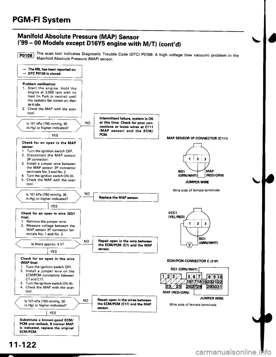
The scan tool indicates Diagnostic Trouble Code (DTC) P0108: A high voltage flow vacuum) problem in theManifold Absolute Pfessure (MAp) sensor,
MAP SENSOR 3P CONNECTOR (C111I
MAPIRED/GRNI
Wire side of female terminals
vcclIYEL/RED)
ECM/PCM CONNECTOR C (31PI
JUMPER WIRE
Wire side of female terminals
Tho MIL has boon rcDortod on.DTC ml 08 b stolod.
Problem verification:'1. Start the engine. Hold theengine at 3,000 rpm with noload (in Park or neutral) untilthe radiator fan comes on, thenlet it idle.2. Check the MAP with the scantoot,
Intormittent f.ilu.e, rystom is OXat thi! time. Chock tor poor con-n6ction3 or looso wirea at C111(MAP 3en.or) and tho ECM/PC-M.
ls 101 kPa (760 mmHg.30in.Hg) or higher indicated?
Check for an open in the MAPaon5('r:1. Turn the ignalion switch OFF.2. Disconnect the MAP sensor3P connector.3. Install a jumper wire betwesnthe MAP sensor 3P conn6ctorterminals No.3 and No.2.4. Turn the ignition switch ON {ll).5. Check the MAP with the scantool.
ls 101 kPa (760 mmHg, 30in.Hg) or higher indicated?
Check fo. an opcn in wiro (SGlline):1. Removo the jumper wire.2. Measure voltage between theMAP sonsor 3P connector terminals No. 1 and No.2.
Roprir opon in tha wiJo bctwoenthc ECM/FCM (C7l rnd the MApsonln t.
ls there approx. 5 V?
Chsck for an open in tho wi.e{MAP lino}:1. Turn the ignition switch OFF.2. Install a jumper wire on theECM/PCM connectors betweenC7 and C17.3. Turn the ignition switch ON (ll).4. Check the MAP with the scantool,
Repair op€n in the wir6a bstwoontho ECM/FCM (C171 and rh6 MApscnltoa.
ls 101 kPa (760 mmHg, 30in.Hg) or higher indicated?
Substituto a known-good ECM/PCM and rechcck, It normal MAPis indiceted. r.place tho originalECM/PCM.
JUMPER WIRE
--
Page 416 of 2189
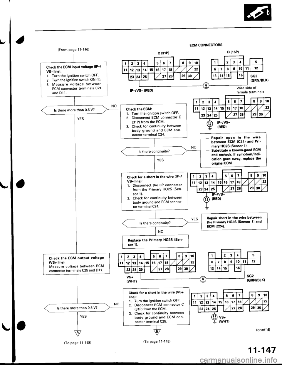
Check the ECM input vottage {lP-/
VS- lino):1. Turn the ignition switch OFF.
2 Turn the ignition switch ON (ll)
3. Measure voltage between
ECM connector terminals C24
Ch.ck the ECM:
1. Turn the ignition switch OFF
2. Disconndct ECM connector C
{31P){rom the ECM.
3. Check lor continuity between
body ground and ECM con
nector terminal C24
ls there more than 0.5 V?
- Repair open in the wire
betw€en ECM {C2{l and Pri-
ma.y HO2S {S€nsor 1 l.- Substitute a known-good ECM
and recheck. It symptom/indi
cation goes away. replace the
odginal ECM.
Check to. r short in the wi.e {lP-/
VS- lin6l:1. Disconnect the 8P connector
from the Primary HO2S lsen-
sor 1).2. Check tor continuity between
body ground and ECM connec-
tor terminal C24
Ropair short in the wire bstween
the Primary HO2S lsensor 1) and
ECM (C24).
Check the ECM output voltage
{VS+ linel:N4easure voltage between ECM
connectorterminals C25 and D11.
Check for a short in the wire (VS+
line):1. Turn the ignition switch OFF.
2. Disconnect ECM connector C
{31P) Irom the ECM.
3. Check {or continuity between
body ground and ECM con
nector terminal C25.
ls there mote than 0.5 V?
ECM CONNECTORS
lFrom page'11-146)c (31PlD {15P)
tP-/vs- tREolfemale termrnals
sG2(GRN/BLKI
(cont'd)
11-147
I23a68910
111213la15t6'171622
232a25272a2930
O rP-/vs-:Z taeot
,l23a55I910
1112131a151617t822
232125212AE30
0) {REDr
23a518910
l11213ta'15't6171822
2321E272A2930
[]) vs*I rwsrt
(To page 11- 148)(To page 11 148)
Page 424 of 2189
Secondary Heated Oxygen Sensor (SecondarytlO2S) (Sensor 2l
('99 - 00 lilodels except DtGYS engine with M/T)
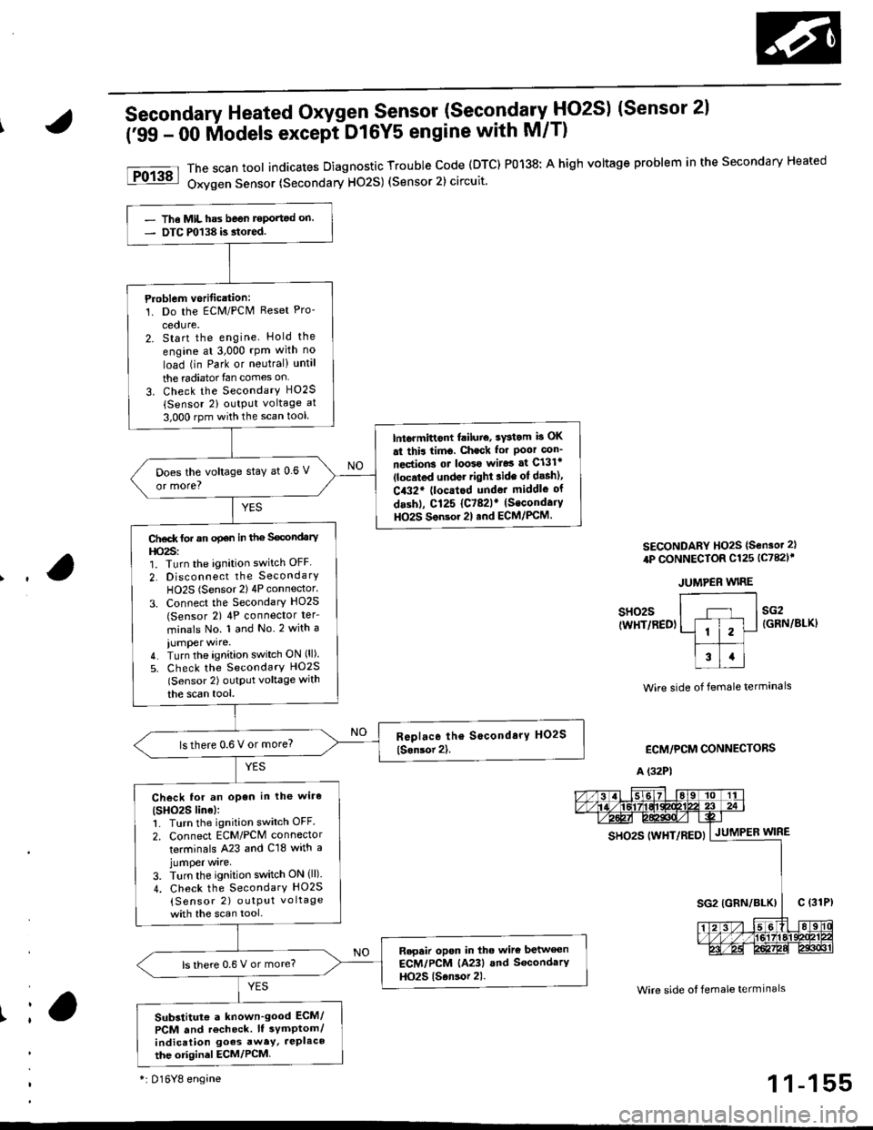
The scan tool indicates Diagnostic Trouble code (DTC) P0138: A high voltage problem in the secondary Heated
Oxygen Sensor (Secondary H02S) (Sensor 2) circuit.
SECONDARY HO2S {S€nsot 2}
4P CONNECTOR Cl25 lc782l'
JUMPER WIRE
Ir
sH02s(WHT/RED)sG2{GRN/BLKI
Wire side of female termanals
ECM/PCM CONNECTORS
A (32P1
Wire side ot female termlnals
gs92g 111yp17p5py | .lutuPea wtne
- The MIL has beon reportod on.- DTC m138 is.tored.
Ploblem vorification:1. Do the ECM/PCN4 Reset Pro-
cedure.2. Start the engine Hold the
engine at 3,000 rpm with no
load (in Park or neutral) until
the radiator{an comes on
3. Check the SecondarY H02S(Sensor 2) output voltage at
3,000 rpm with the scan tool
lntormittont failuio, sYstom b OK
st thir timo. Check for Poor con_
nections ot loo39 wiJo3 af Cl3lr(located under right ride ot desh),
C432' (locatod undot middle of
dashl, Cl25 {C782lr (Secondaiy
HO2S Son3or 2l and ECM/PCM.
Does the voltage stay at 0 6 V
or more?
Ct€d( tor an opan in the Secondary
l|o2s:1. Turn the ignition switch OFF
2. Disconnect the SecondarY
HO2S (Sensor 2) 4P connector.
3. Connect the Secondary HO2S(Sensor 2) 4P conneclor ter_
minals No. 1 and No.2 with a
iumper wire.4. Turn the ignition switch ON (ll)
5. Check the SecondarY HO2S
lSensor 2) outptlt voltage with
the scan tool,
lsthere 0.6 V or more?
Check lor an open in the wiro(SHO2S line):1. Turn the ignition switch OFF.
2. Connect ECM/PCM connector
terminals A23 and C18 with ajumper wrre,
3. Turn the ignition switch ON (ll).
4. Check the SecondarY HO2S
{Sensor 2) outPut vo ltage
with the scan tool.
Repair opon in tho wire betwecn
ECM/PCM (A23) and SocondarY
HO2S {Sansor 2).ls there 0.6 V or more?
Substitut€ a known'good ECM/
PCM and recheck. It symptom/indication goes awey, JePlaco
the otiginel ECM/PCM
*i 016Y8 engine1 1-155