3-23 HONDA CIVIC 1997 6.G Workshop Manual
[x] Cancel search | Manufacturer: HONDA, Model Year: 1997, Model line: CIVIC, Model: HONDA CIVIC 1997 6.GPages: 2189, PDF Size: 69.39 MB
Page 46 of 2189
Specifications
Standards and Service Limits "'.".'.""' 3-2
Design Specif ications,..'....,.'..'.... "... ""' 3-20
Body Specifications "'."'." 3-23
Page 581 of 2189
\
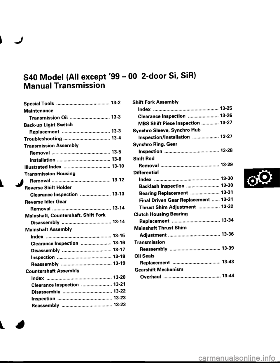
S40 Model (All except'99 - 00 2-door Si' SiR)
Manual Transmission
Special Tools ..'.......... 13-2
Maintenance
Transmission Oil .............................. 13-3
Back-up Light Switch
Replacement ......... 13-3
Troubleshooting '....... 13-4
Transmission AssemblY
Removal ................. 13-5
lnstallation ............. 13-8
lllustrated Index ...............'........."........ 13-10
Transmission Housing
I Removaf .."""""""' 13-12
J R"rr"r"" Shift Holder
Clearance lnspection ....................... 13-13
Reverse ldler Gear
Removal ....'.........." 13-14
Mainshaft, Countershaft, Shift Fork
Disassembly ......'... 13-14
Mainshaft AcsemblY
Index ............... ....... 13-15
Clearance Inspection ..'.................... 13-16
Disassembly .......... 13-17
Inspection ....'......... 13-18
Reassembly ........... 13-19
Countershaft AssemblY
lndex ................ ...... 13-20
Clearance lnspection ."..........'......." 13-21
Disassembly ..."""' 13-22
Inspection .............. 13-23
Reassembly ..'.""... 13-23
Shift Fork AssemblY
lndex ............... ."'... 13-25
Clearance lnspection ."......."........'.. 13'26
MBS Shift Piece Inspection ....-.....'.. 13'27
Synchro Sleeve, Synchro Hub
f nspection/lnstallation .......'...... ".... 13'27
Synchro Ring, Gear
Inspection '....'..".... 13'28
Shift Rod
Removal .'......".""" 13'29
Differential
lndex ......."'...... .'."' 13-30
Backlash Inspection ..........."......."... 13-30
Bearing Beplacement'.............'.".... 13'31
Final Driven Gear Replacement '..... 13-31
Thrust Shim Adiustment ..."........... 13-32
Clutch Housing Bearing
Replacement .......'. 13-34
Mainshaft Thrust Shim
Adiustment '....'..".. 13-36
Transmission
Reassembly ........... 13-39
Oil Seals
Replacement ......... 13-43
Gearshift Mechanism
Overhaul ................ 13-44
\
Page 600 of 2189
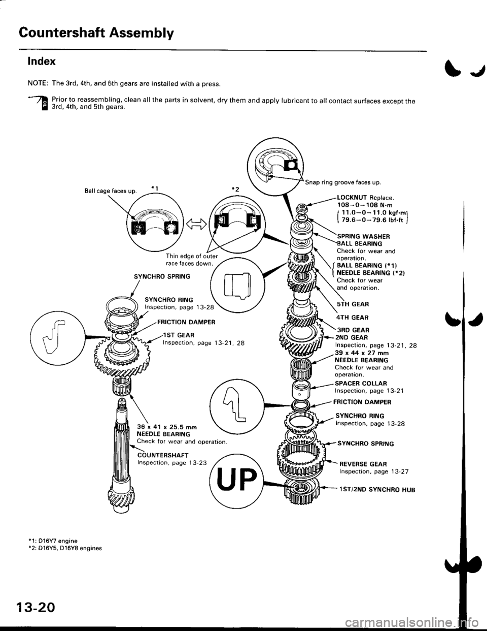
Countershaft Assembly
Index
I.r
NOTE:
-re
The 3rd, 4th, and sth gears are installed with a press.
Prior_to reassembling, clean all the parts in solvent, dry them and apply lubricant to all contact surfaces except the3rd, 4th, and 5th gears.
Snap ring groove faces up.
LOCKNUT Replace.108-O- 108 N.m
I 11.0-O-11.0 kst.ml
I 79.6-0- 79.6 lbt.ft I
SYNCHRO SPRING
SYNCHRO RINGInspectaon, page 13-28
FRICTION DAMPER
Thin edge ol outerrace faces down.
Check for wear andoperatron,
/ BALL EEAR|NG t*1)
t NEEDLE BEARTNG (.2)
Check for wearand operatron,
WASHERBEARING
GEAR
4TH GEAR
3RD GEAR2ND GEAR
FRICTION DAMPER
SYNCHRO SPRING
SYNCHRO RINGInspection, page 13-2836 x 41 x 25.5 mmNEEDLE BEARINGCheck for wear and operataon.
Inspection, page 13-23
1ST GEARlnspection, page 13 21, 28lnspection, page 13-21, 2839x44x27m�mNEEDLE BEARIfI'GCheck for wear andoperation.
SPACER COLLARInspection, page 13-21
REVERSE GEARlnspection, page 13 27
1ST/2ND SYNCHRO HUB
*1: D'16Y7 engine*2: D16Y5, D16Y8 engines
13-20
Page 603 of 2189
Inspection
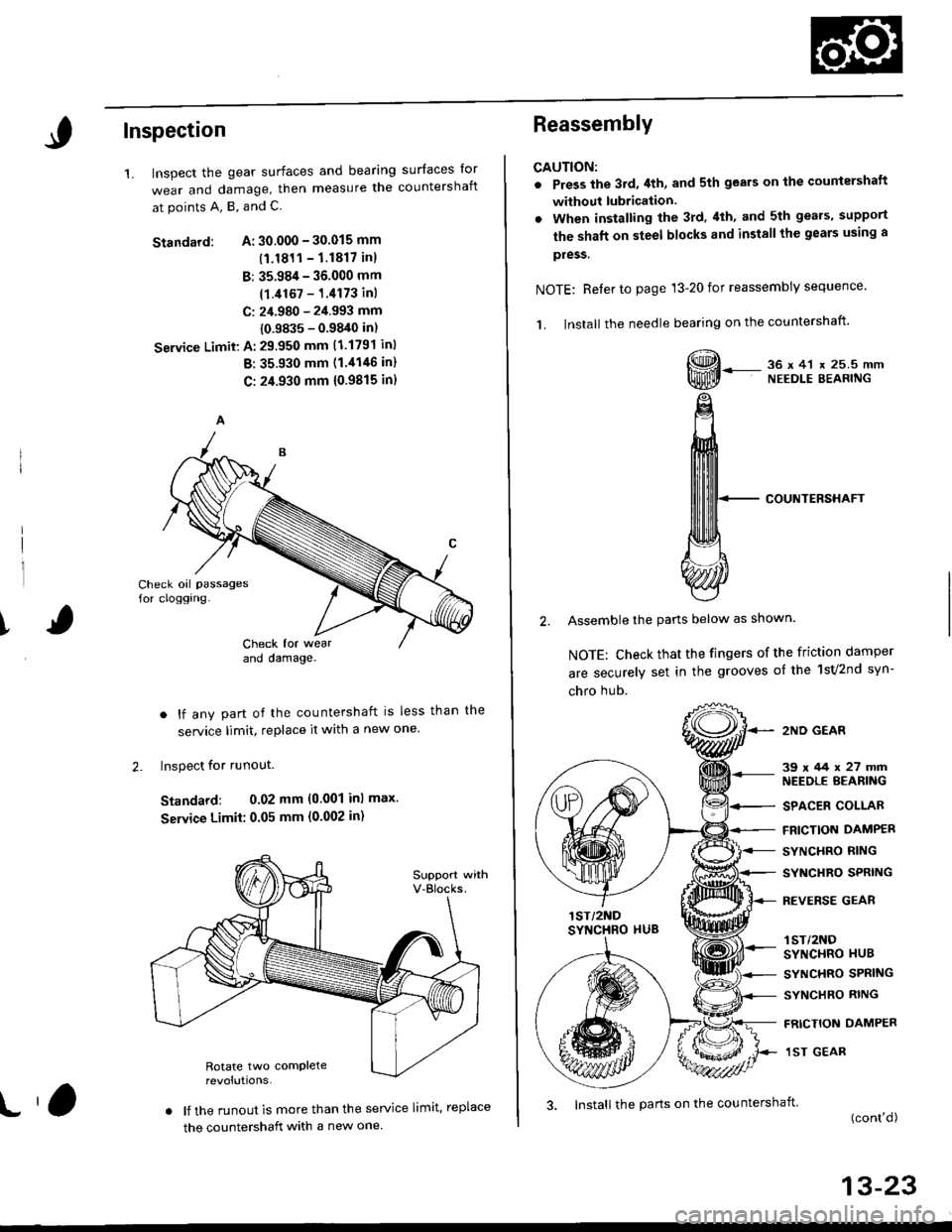
1.surfaces lor
countershaftInspect the gear surfaces and bearang
wear and damage, then measure tne
at points A, B, and C.
Standard: A: 30.000 - 30.015 mm
(1.1811- 1.1817 inl
B: 35.984 - 36.000 mm
(1.i1167 - 1.4173 inl
C: 24.980 - 2i1.993 mm
{0.9835 - 0.9840 in)
Seryice Limit: A: 29.950 mm (1.1791 inl
B: 35.930 mm (1 '1146 in)
C: 24.930 mm 10.9815 in)
Check oil passages
for cloggrng-
ICheck for wearano oamage.
. lf any part of the countershaft is less than
service limit, replace it with a new one.
Inspect for runout.
Standard: 0.02 mm (0.001 inl max.
Seryice Limit: 0.05 mm {0'002 in)
. lf the runout is more than the service limit. replace
the countershaft with a new one.
the
2.
t,3. Install the parts on the countershait
Reassembly
CAUTION:
. Press the 3rd,4th, and sth gears on the countershaft
without lubrication.
. When installing the 3rd. 4th, and 5th geals, support
the shaft on steel blocks and installthe gears using a
pless.
NOTE: Reler to page 13-20 for reassembly sequence'
1. lnstall the needle bearing on the countershaft'
, 36x41 x 25.5mmNEEDLE BEARING
COUNTERSHAFT
2. Assemble the pans below as shown.
NOTE: Check that the fingers of the friction damper
are securely set in the grooves of the 1sv2nd syn-
chro hub.
2ND GEAR
39x/+4x27mmNEEDLE BEARING
SPACER COLLAR
FRICTION DAMPER
SYNCHRO RING
SYNCHRO SPRING
REVERSE GEAR
lST/2NOSYNCHRO HUB
SYNCHRO SPRING
SYNCHRO RING
FRICTION DAMPER
1ST GEAR
(cont'd)
13-23
Page 1471 of 2189

l'f .
Electrical
Special Toofs .,....................,23-2
Troubleshooting
Tips and Precautions ..............,.................... . 23-3
Five-step Troubleshooting .............. ......... . . 23-5
wire color codes ..........,23-5
Schematic Symbols ........,................... . . .. .... 23-6
Relay and Control Unit Locations
Engine Compartment ...,..................... ... .. . 23'7
Dashboard ......................23-8
Dashboard/Door ......... 23-12*Airbags ................. ....... Section 24
Air Conditioning ......... Section 21
Aftelnator ..........."""" """ 23-112
Anti-lock Brake System {ABS) Section 19*A/T Gear Position Indicator .....................,. .... ... 23-149
Automatic Transmission Svstem .... . ....... Section 14
Batterv ......... . . . ... ...... .......23-91
Blower controls .. . ... Section 2l
Charging System ....'...........23'112
Connector ldentilication and Wire Harness
Routing .................. ......23'13
Cruise Control ............,........23-240
Dash Lights Brightness Controller ............. ....... 23-180
Fan controfs "" 23'126
Fuel PumD ........ . ........ section 11
Fuses/Refay ...............,..,,.. 23'62
PGM-FI Control System ......................,....... Section 1 1
*Gauges
Circuit Diagram ....,.,.......23-131
Fuef Gauge ...........'.'.......23-142
Gauge/lndicator .. . .. 23-129
Ground Distribution .. . 23-75
Heatei controls .. . ..... Section 21*Horn................. ...............23-196
*tgnition Switch ....................23-89
lgnition System .......,.... 23-102
*lntegrated Control Unit ....................................... 23-156
fnterlock System ,........ . . , ,23-144
Lighting System . . . .. ......... 23-161
Lights, Exterior
Back-up Lights ..'............23'171
Brake Lights .................. 23'174
Daytime Bunning Lights (Canadal ............... 23'166
Front Parking Lights ......,................ .'. .......... 23-167
Front Turn Signal Lights .......... . . ............ ..,.23-167
Headtights ....".'....-... ..... 23'167
High Mount Brake Light ...................... ... .23'179
License Plate Lights ...... 23'176
Taitfights ................ .......23'171
lnterior Lights ..-.......,, . 23-142
Moonroof ..,.................,........ 23-235
Power Distribution ....... . . .23-61
Power Door Locks .......,,,. .23'251
Power Mirrors ,..............,.,...23'206
Power Relays ....... . ...... . . .. 23-86
Power Windows ............,,....23-220
Rear Window Defogger .......................... . . ... . . 23-2OO
Spark Plugs . ..... . ........ .....23-111
Slarting System ................23-93*stereo Sound Svstem ,................. ..... ... . ... ,.,.,,23'147'Supplemental Restraint System (SRS) ... . Section 24
Turn Signal/Hazard Flasher System .......'.'....-... 23-173
*Undel-dash Fuse/Relay Box ............,.................. 23-85
vehicfe soeed sensor (VSSI """" ""' 23-140+Wipers/Washers .........,.,.,...23-214
NOTE: Unless otherwise specified, references to auto-
matic transmission (Mf) in this section include the CVT.
Page 1493 of 2189
D
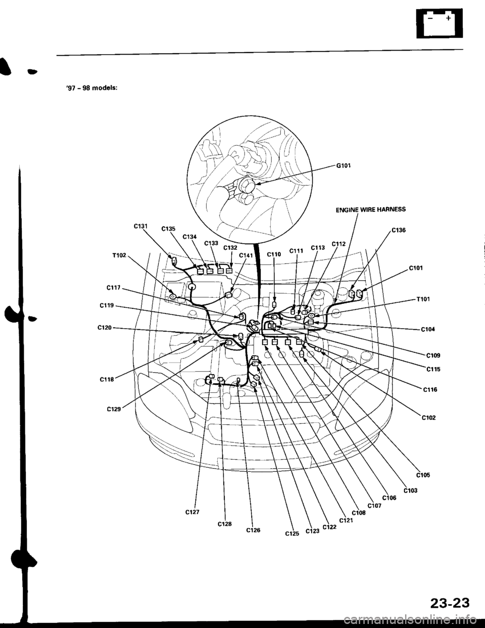
'97 - 98 models:
WIRE HARNESS
23-23
Page 1690 of 2189
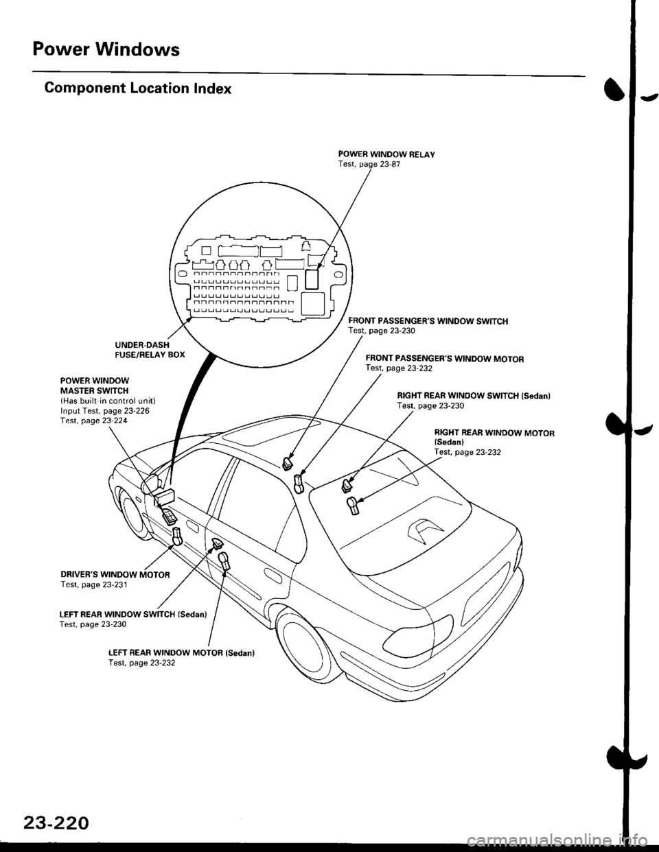
Power Windows
Gomponent Location Index
UNDER-DASHFUSE/RELAY BOX
POWER WINDOW RELAYTest, paqe 23 87
FRONT PASSENGER'S WINDOW SWITCHTest. page 23-230
FRONT PASSENGER'S WINDOW MOTORTest, page 23-232
POWER WINDOWMASTER SWITCH(Has built in control unit)Input Test, page 23-226f e$, page 23 224
RIGHT REAR WINOOW SWITCH {SedanlTest, page 23-230
BIGHT REAR WINDOW MOTORlSedanlTest, page 23-232
DRIVER'S WINOOW MOTORTest, page 23-231
LEFT REAR WINDOW SWITCH (Sedan)
Test, page 23-230
LEFT BEAR WINDOW MOTOR {Sedanlf e$, page 23-232
O -rr----r---- _ fl]l O-.---,---;-; n-n--n-nn--r- ! l
Page 1700 of 2189
Power Windows
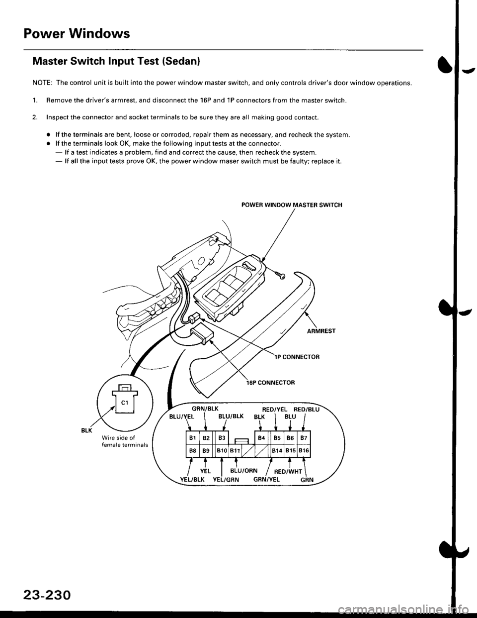
Master Switch Input Test (Sedan)
NOTE: Thecontrol unit is built intothe power window master switch, and only controls driver's door window operations.
1. Remove the driver's armrest, and disconnect the 16P and 1P connectors from the master switch.
2. Inspect the connector and socket terminals to be sure they are all making good contact.
a lf the terminals a re bent, loose orcorroded, repairthem as necessary, and recheck the system.
. lf the terminals look OK, make the following input tests at the connector.- lf a test indicates a problem, find and correct the cause, then recheck the system.- lf all the input tests prove OK. the power window maser switch must be faulty; replace it.
POWEB WINDOW MASTER SWITCH
23-230
Page 1701 of 2189
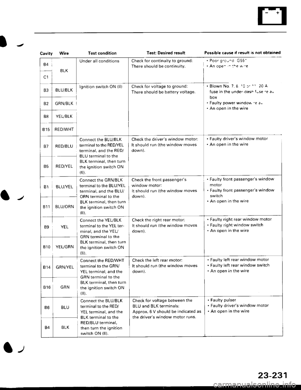
CavityWireTest conditionTest: Desired resultPossible caus! d r"suh rs nol obtrincd
to:
c1
BLK
UnderallconditionsCheck for continuity to groundl
There should be continuity., An ope^ ^ :he tt .e
. Blown No.7.6 10 r' " 20 A
fuse in the unde. oast f.se 'e a,
box. Faulty power windo$ 'e a,. An open in the wire
B3BLU/BLKlgnition switch ON (ll)Check for voltage to grou nd:
There should be battery voltage.
B2GRN/BLK
YE L/BLK
R EDA/VHT815
81RED/BLU
RED/YEL
Connect the BLU/BLK
terminal to the RED/YEL
terminal, and the RED/
BLU terminal to the
BLK terminal, then turn
the ignition switch ON
1I i.
Check the driver's window motorl
It should run (the window moves
oown).
. Faulty driver's window motor
. An open in the wire
B1BLUIVEL
Connect the GRN/BLK
terminal to the BLU|YEL
terminal, and the BLU/
Check the front passenger's
wrnoow motor:
It should run (the window moves
Fau lty front passenger's window
motor
Faulty front passenger's window
An open in the wire
811BLU/ORNBLK terminal, then turn
the ignition switch ON
0 r).
B9YEL
connect the YEL/BLK
terminal to the YEL ter-
minal, and the YEU
GRN terminal to the
BLK terminal, then turn
the ignition switch ON
0 r).
Check the right rear motor:
It should run (the window moves
down).
Fauity right rear window motor
Fau lty right window switch
An open in the wire
Bt0YEUGRN
814GRNI/EL
connect the RED,ryVHT
terminal to the GRN/
YEL terminal, and the
GRN terminal to the
BLK terminal, then turn
the ignition switch ON
0 r).
Check the left rear motor:
It should run (the window moves
Faulty left rear window motor
Faulty left rear window switch
An open in the wire
816GRN
B6BLU
Connect the BLU/BLK
terminal to the RED/
YEL terminal, and the
BLK terminal to the
RED/BLU terminal,
then turn the ignition
switch ON (ll).
Check for voltage between the
BLU and BLK terminalsl
Approx. 6 V should be indicated as
the driver's window motor runs.
Faulty pulser
Faulty driver's window motor
An open in the wire
B4BLK
23-231
Page 1702 of 2189
Power Windows
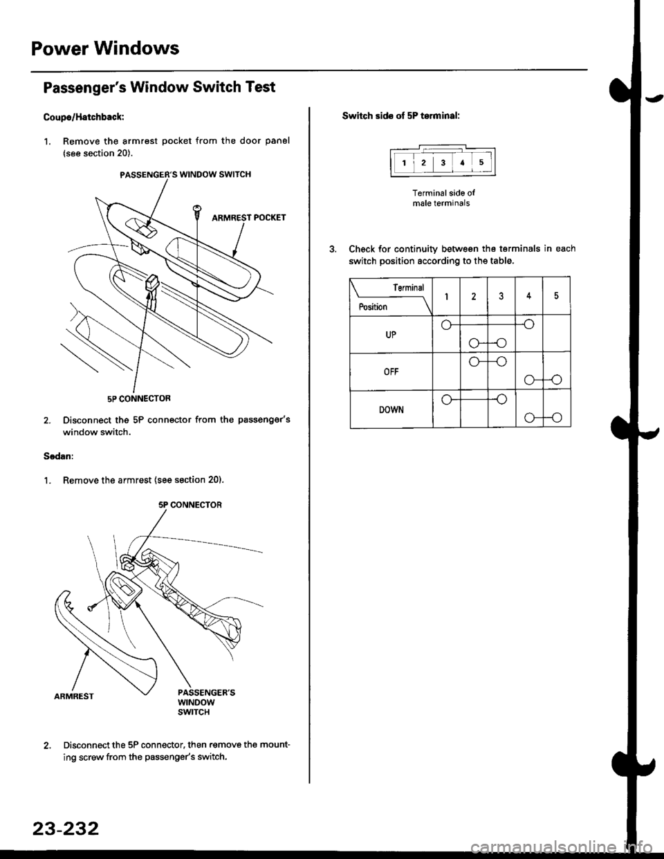
Passenger's Window Switch Test
Coupo/H8tchback:
1. Remove the armrest pocket from the door panel
{see section 20}.
5P CONNECTOR
2. Disconnect the 5P connector from th€ passenger's
window switch.
Sodan:
1. Remove the armrest (see section 20).
Disconnect the 5P connector, then .emove the mount-
ing screw from the passenge/s switch.
PASSENGER'S WINDOW SWITCH
5P CONNECTOR
23-232
Switch sids of 5P t.rminal:
Terminal side olmale terminals
Check for continuity between the terminals in each
switch position according to the table.
12a5
Terminal
il;--lI25
UP
-o
-o
OFF
-o
o--o
DOWNo--o