Transmission
17.
Installation (cont'd)
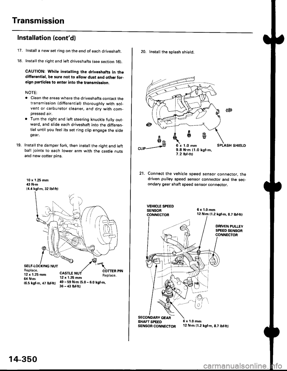
Install I new set ring on the end of each driveshaft.
Install the right and left driveshafts (see section 16).
CAUTION: While instatling the drive3hafts in thedifferential, be sure not to allow dust and olher for-aign particles to enter into tho transmission.
NOTE:
. Clean the areas where the driveshafts contact thetransmission {differential} thoroughly with sol-vent or carburetor cleaner, and drv with com-
Dressed air.
. Turn the right and left steering knuckle fully out-wa.d, and slide each driveshaft into the differen-tial until you feel its set ring clip engage the sidegear.
Install the damper fork, then install the right and leftball joints to each lower arm with the castle outsand new cotter pins.
19.
10 x 1.25 mm43 N.m{4.4 kgf.m, 32 lbf.ftl
SELF-LOCKING NUTReplace.12 x 1.25 mm6l N.m
CASTI.I'12 x 1.25 mm
{6.s ksr.m. 47 tbr.ftr l! _ ll ffiteo
- s.o tet'.,
14-350
20. Install the splash shietd.
aa
I6I6*
"a,a s
21.
SECONOARY GEARSHAFT SPEEDSENSOB CONNECTOR
6 x 1.0 mm9.8 t{.m 11.0 kgt.m,7.2 tbf.trl
Connect the vehicle speed senso. connector. thedriven pulley speed sensor connector and the sec-ondary gear shaft speed sensor connector,
6x1,0mm12 N.m {1.2 kg{.m, 8.7 tbf,ft)
DRIVEN PULLEYSPEED SENSORCONNECTOR
E.
6 x 1.0 m.rl'12 N.m {1.2 kg{.m,8.7 tbf.fo