Fuel reset HONDA CIVIC 1997 6.G Workshop Manual
[x] Cancel search | Manufacturer: HONDA, Model Year: 1997, Model line: CIVIC, Model: HONDA CIVIC 1997 6.GPages: 2189, PDF Size: 69.39 MB
Page 408 of 2189
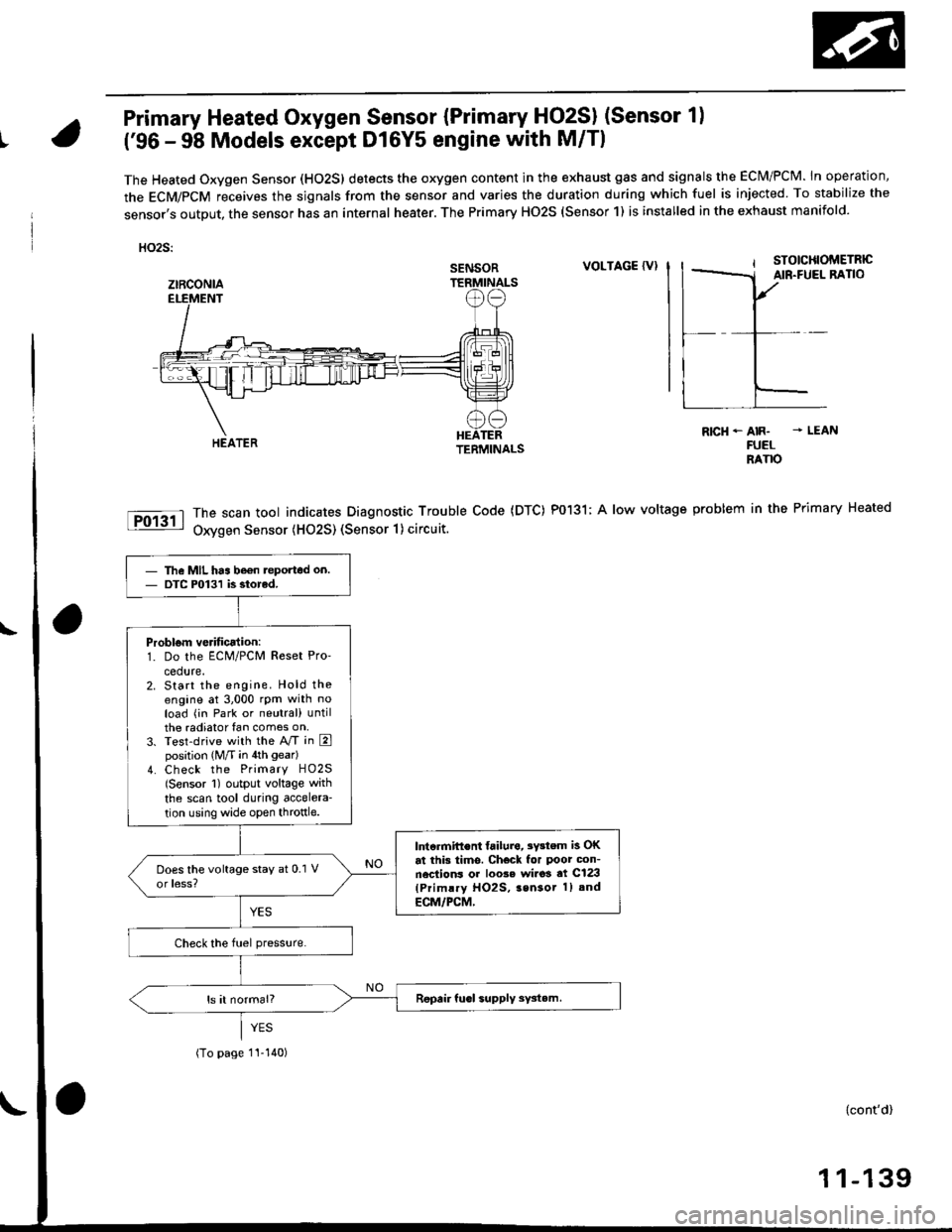
Primary Heated Oxygen Sensor {Primary HO2SI (Sensor 1)
t('96 - 98 Models except Dl6Y5 engine with M/Tl
The Heated Oxygen Sensor (HO2S) detects the oxygen content in the exhaust gas and signals the ECM/PCM. In operation,
the ECM/PCM receives the sjgnals from the sensor and varies the duration during which fuel is injected To stabilize the
sensor,s output, the sensor has an internal heater. The Primary HO2S (Sensor 1) is installed in the exhaust manifold.
HO2S:
VOLTAGE {VI
The scan tool indicates Diagnostic Trouble Code (DTC) P0131; A low voltage
Oxygen Sensor (H02S) (Sensor 1) circuit.
R|cH-AIR- - LEANFUELRANO
problem in the Primary Heated
SENSOR
ztRcoNlA
The MIL has be€n teported on.DTC P0131 is siorcd.
Problom verificalion:1. Do the ECM/PCM Reset Pro'
cedure.2. Start the engine. Hold theengine at 3,000 rpm with noload (in Park or neutral) untilthe radiator fan comes on,3. Test-drive with the A/T in Eposition (M/T in 4th gear)
4. Check the Primary HO2S(Sensor 1) output voltage with
the scan tool during accelera-
tion using wide open throttle.
lntcrmift€nt failura, 3Y3tem is OKat this tims. Check for Poor con-nections or loo3e wi.o3 at C123(Primlry HO2S, 3sn3or 1) and
ECM/PCM,
(To page 1I-140)
{cont'd)
1 1-139
Page 410 of 2189
Primary Heated Oxygen Sensor (Primary- Fjq?S) (Sensor 1l
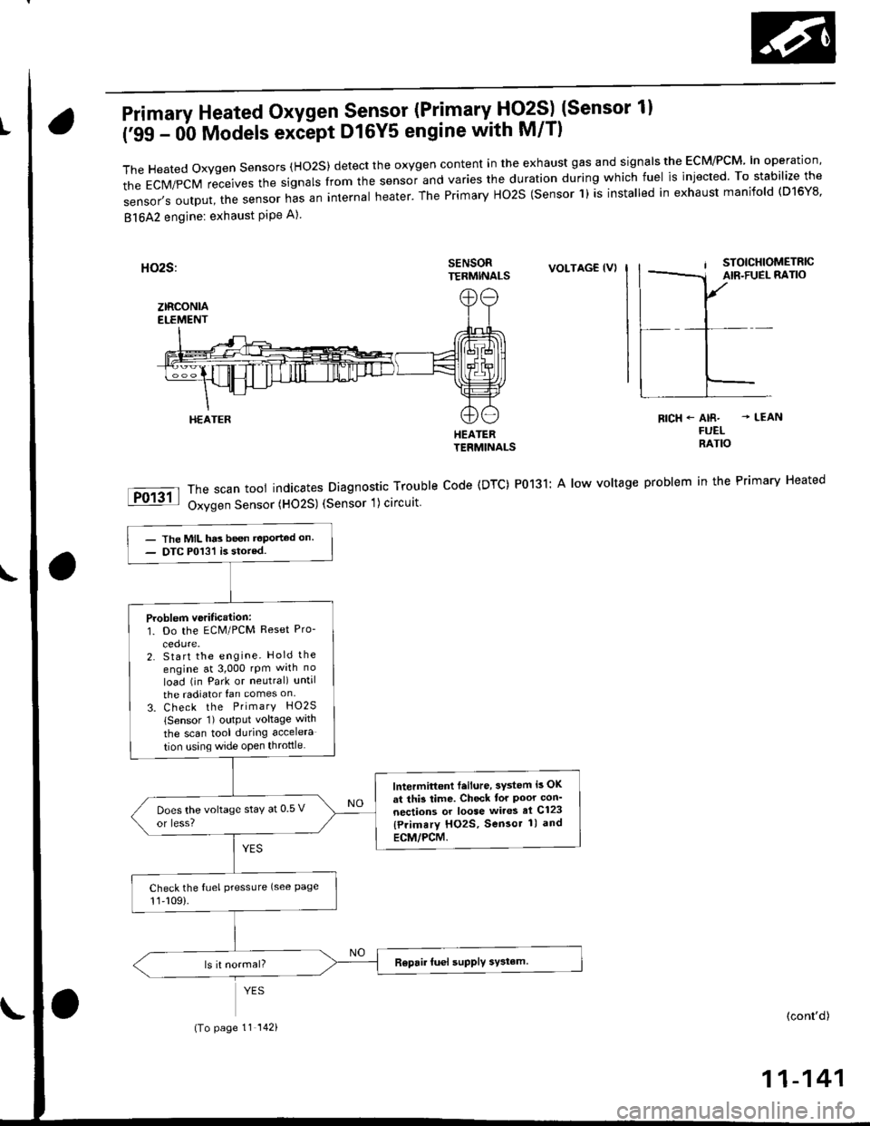
('99 - 0b Models exiept D16Y5 engine with M/T)
TheHeatedoxygensensors(Ho2S)detecttheoxygencontentintheexhaustgasandsigna|stheEcM/PcM'|noperation,
the EcM/pcM receives the signars from the sensor and varies the duration during which fuel is injected. To stabilize the
sensor,soutput,thesensornasaninternaIheater.ThePrimaryHo2S(sensorl)isinsta|ledinexhaustmanifo|d(D16Y8.
81642 engine: exhaust PiPe A)
SENSORTERMINALSVOLTAG€ (VI
HEATERTERMINALS
The scan tool indicates Diagnostic Trouble Code (DTC) P0131: A low voltage
Oxygen Sensor (HO2S) (Sensor 1) circuit
RICH+ AIR- - LEANFUELRATIO
problem in the Primary Heated
HEATER
- The MIL has been t€Ported on.- DTC P013'l is stored.
Problem veritication:1. Do the ECM/PCM Reset Pro-
2. Start the engine. Hold the
engine at 3,000 rpm wrth no
load (in Park or neutral) until
the radiator fan comes on
3. Check the PrimarY HO2S
lSensor 1) output voltage wath
the scan tool during accelera
tion using wide open throttle
lntermittont f.ilure, 3ystem i3 OK
at thi3 time. Check tor Poor con'
nections or loose wires el C123
{Primary HO2S, Sensor 1) and
ECM/PCM.
Does the voltage stay at 0 5 v
or less?
Check the fuel pressLlre (see Page11,109).
(To page 11 142)(cont'd)
11-141
Page 414 of 2189
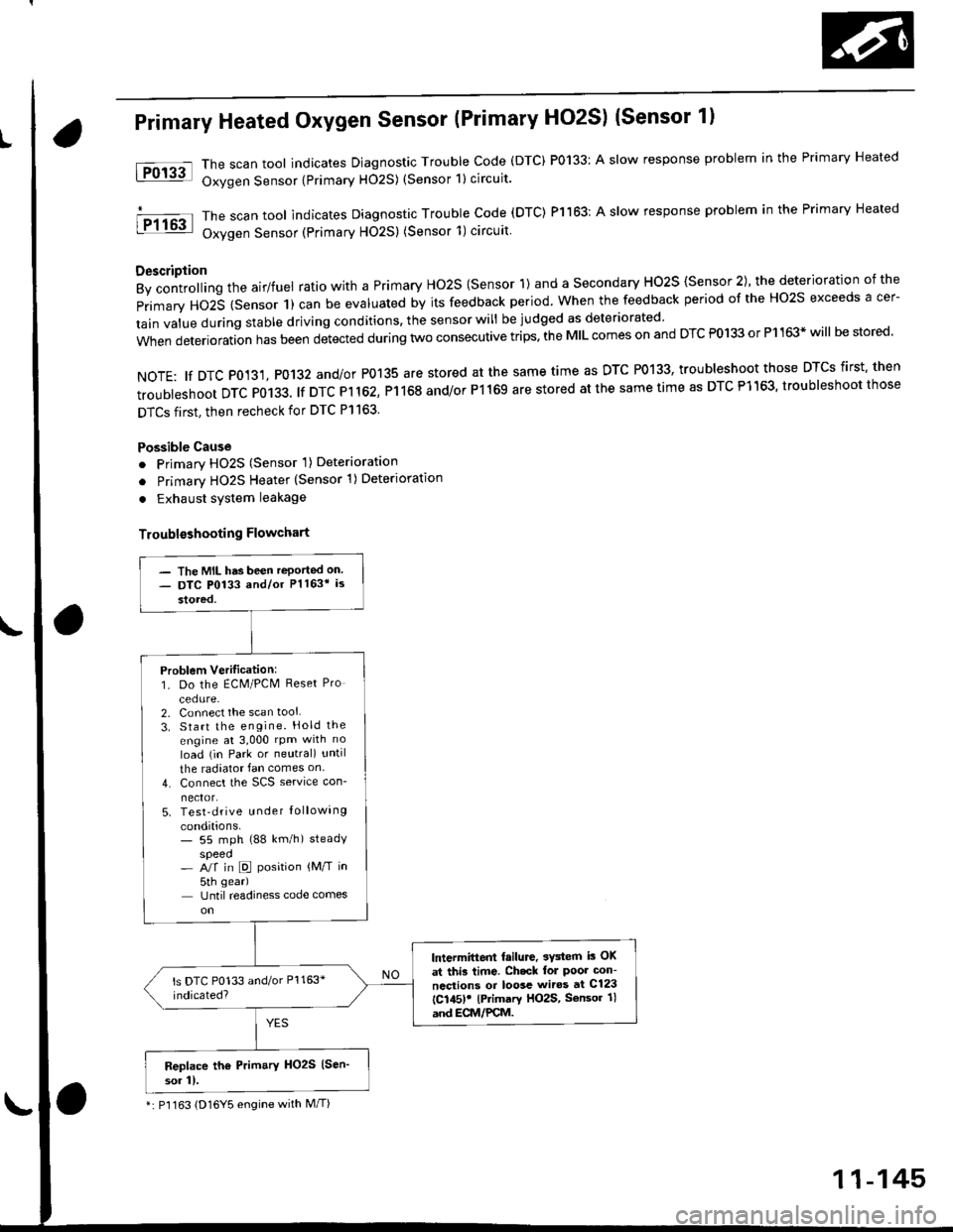
Primary Heated Oxygen Sensor (Primary HO2S) (Sensor 1l
The scan tool indicates Diagnostic Trouble Code (DTC) P0133: A slow response problem in the Primary Heated
Oxygen Sensor {Primary H02S) (Sensor 1) circuit.
The scan tool indicates Diagnostic Trouble code (DTC) Pl163: A slow response problem in the Primary Heated
Oxygen Sensor (Primary HO2S) (Sensor 1)circuit
Description
By controlling the airlfuel ratio with a Primary Ho2S {Sensor 1) and a secondary HO2S {Sensor 2), the deterioration of the
primary HO2S (Sensor 1) can be evaluated by its feedback period. when the feedback period of the Ho2s exceeds a cer-
tain value during stable driving conditions, the sensor will be judged as deteriorated
when deterioration has been detected during two consecutive trips. the MIL comes on and DTC P0133 or P1163* will be stored'
NOTE: tf DTC P0131, P0132 and/or P0135 are stored at the same time as DTC P0133, troubleshoot those DTCS first' then
troubleshoot DTC P0133. lf DTC Pl 162, P1168 and/or P1169 are stored at the same time as DTC P1163, troubleshoot those
DTCS first, then recheck for DTC Pl163.
Possible Cause
o Primary HO2S (Sensor 'l) Deterioration
o Primary HO2S Heater (Sensor 1)Deterioration
. Exhaust system leakage
Troublsshooting Flowchart
tFol3al
I P1163
- The MIL has been reported on- DTC P0133 and/or Pl163* is
stored,
Problem Verilication:1. Do the ECM/PCM Reset Pro
cedure-2. Connect the scan tool
3. Start the engine. Hold the
engine at 3,000 rpm with no
load (in Park or neutral) until
the radiator fan comes on
4. Connect the SCS service con-
nector.5. Test-drive u nder Iollowing
conditions.- 55 mph (88 km/h) steadyspeed- A/f in D position {M/T in
5th gear)
Until readiness code comes
lntermittent failure, 3Y3tem i3 OK
at thi3 time. Ch.ck lol Poor con-
ncctions or loosc wiros at C123
{C145)! lPrimary HO2S, Sensor 1l
and ECM/PCM.
Replace th6 Prim.ry HO2S (Sen'
sor 11.
*: P'l163 (D16Y5 engine with M/T)
11-145
Page 415 of 2189
PGM-FI System
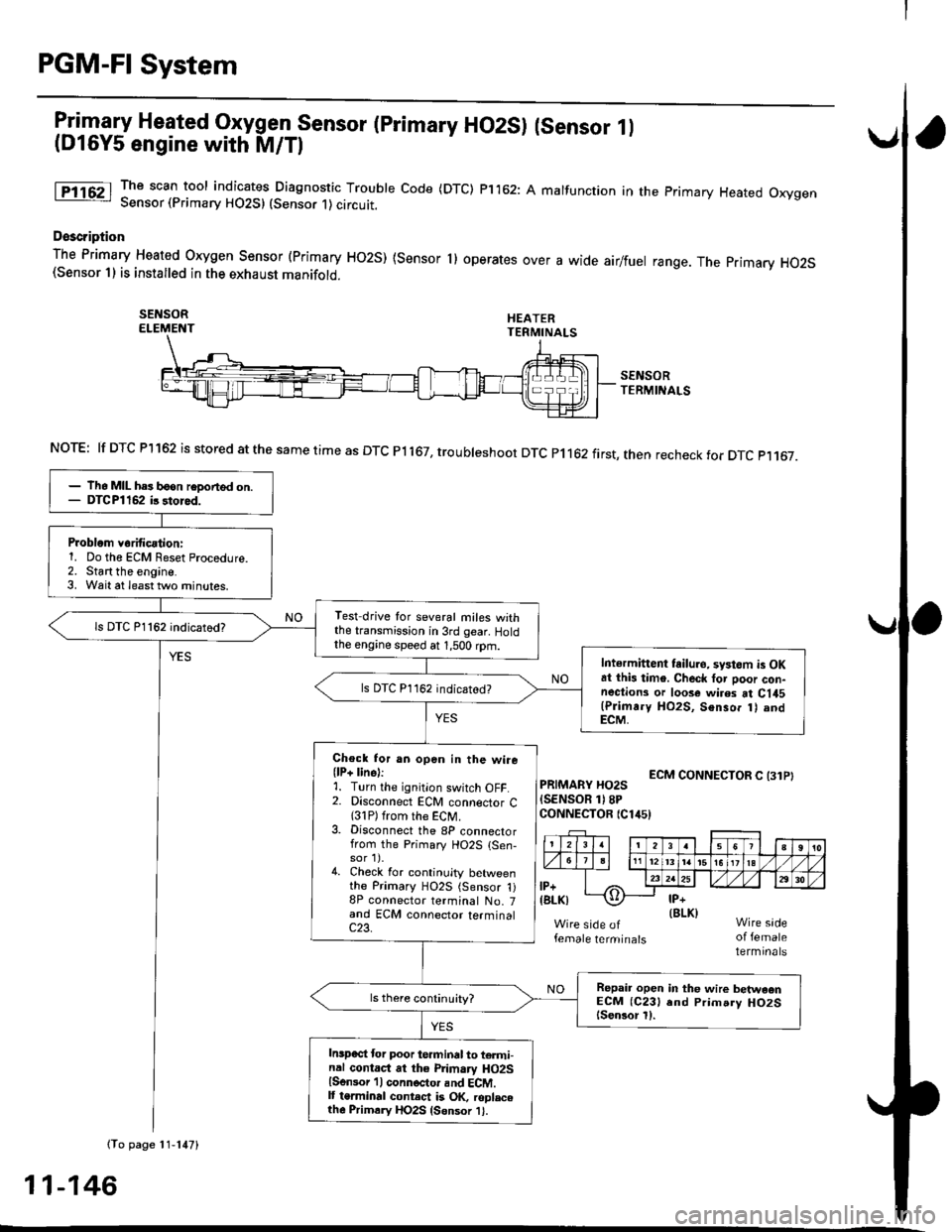
Itil-"w Heated Oxygen Sensor (primary HO2S) (sensor 1l(Dl6Y5 engine with M/Tl
The scan tool indicates Diagnostic Trouble Code (DTC) p1162: A malfunction in the primary Heated OxygenSensor (Primary HO2S) (Sensor 1) circutt.
Doscription
The Primary Heated orygen sensor (Primary Ho2s) {sensor 1) operates over a wide airlfuel range. The primary Ho2S(Sensor 1) is installed in the exhaust manifold.
SEI{SORELEMENT
SENSORTERMINALS
ECM CONNECTOR C (31PIPRIMARY HO2S(SENSOR 1)8PCONNECTOR {Clir5)
female terminalsof femaleterminals
NOTE: lf DTC Pl162 is stored at the same time as DTC Pl167, troubteshoot DTC p1162 first, then recheck for DTC p1167.
(To page 11-147)
- lh6 MIL hes b6on reDorted on.- DTCPl162 ir 3tored.
Problom v6rificationi1. Do the ECM Reset Procedure.2. Start the engine.3. Wait at least tlvo minutes.
Test drive tor several miles withthe transmission in 3rd gear. Holdthe engine speed at 1,500 rpm.
ls DTC P1162 indicatod?
Intermittent tailuro, systom is OKat this timo. Check tor poor con-nections or loose wires at C145(Plimr.y HO2S, Senso. t) andECM,
ls DTC P1162 indicated?
Chock for an open in the wire(lP+ lins):1. Turn the ignition switch OFF.2. Disconnect ECM connector C{31P) from the ECM.3. Disconnect the 8P connectorfrom the Primary HO2S {Sen-sor 1).4. Check for continuity betweenthe Primary HO2S (Sensor 1)8P connector terminal No. 7and ECM connector terminalc23.
Repair open in the wire betwaonECM (C231 end Prim.ry HO2Slsen3or l).
Inspect lor poor terminal to termi-nal contact at the Primary HO2Slsensor 'l I connoctor and ECM.It terminal contect is OK, roplacelh6 Primrry HO2S {Sensor 1}.
11-146
Page 437 of 2189
PGM-FI System
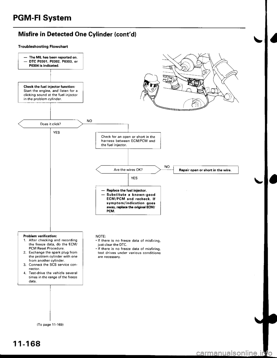
Misfire in Detected One Gylinder (cont'dl
Troubleshootin g Flowchart
NOTE:. lf there is no treeze data of misfiring,just clear the DTC.. It there is no freeze data of misfiring,test drives under various conditions
- The MIL has been reoorted on.- DTC P0301. P0302. P0303, orP030il is indicated.
Check the fuel iniecto. lunction:Stan the engine, and listen for aclicking sound at the fuel injectorin the problem cylinder.
Check for an open or short in theharness between ECM/PCM andthe fuel iniector.
Repair open or short in the wir€.
Replace the fuel iniector.Sub3titute a known-goodECM/PCM and recheck. Itsymptom/indication goesaway, replace the original ECM/PCM.
Problem verification:1. After checking and recordingthe freeze data, do the ECM/PCM Reset Procedure.2. Exchange the spark plug fromthe problem cylinder with onefrom another cylinder,3. Connect the SCS service con'nector,4. Test-drive the vehicle severaltimes in the range ofthe free2edata.
(To page 11-169)
1 1-1 68
Page 441 of 2189
PGM-FI System
tFos3sl
tFffi6l
tPr361 I
fPfi62l
fFr38il
tF13s2-l
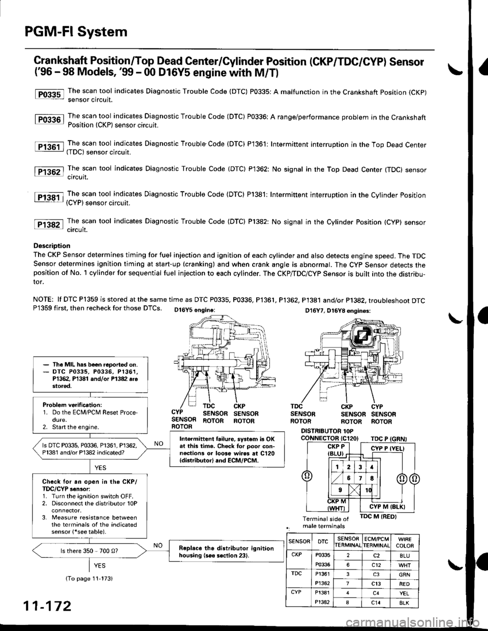
Crankshaft Position/Top Dead Genter/Gylinder Position (CKP/TDC/CYP) Sensor
('96 - 98 Models, '!n - 00 D16Y5 engine with M/Tl
The scan tool indicates Diagnostic Trouble Code (DTC) P0335: A malfunction in the Crankshaft position (CKp)
sensor circuit.
The scan tool indicates Diagnostic Trouble Code (DTC) P0336: A range/performance problem in the CrankshaftPosition (CKP) sensor circuit.
The scan tool indicates Diagnostic Trouble Code (DTC) P1361: Intermittent interruotion in the Too Dead Center(TDC) sensor circuit.
The scan tool indicates Diagnostic Trouble Code {DTC) P1362: No signal in the Top Dead Center (TDC} sensorcircuit.
The scan tool indicates Diagnostic Trouble Code (DTC) P1381: Intermittent interruption in the Cvlinder Position{CYP) sensor circuit.
The scan tool indicates Diagnostic Trouble Code {DTC) Pl382: No signal in the Cylinder Position (CYP} sensorcircuit.
Description
The CKP Sensor determines timing for fuel injection and ignition of each cylinder and also detects engine speed. The TDCSensor determines ignition timing at start-up (cranking) and when crank angle is abnormal. The Cyp Sensor detects theposition of No. 1 cylinder for sequential fuel injection to each cylinder. The CKP/TDC/CYP Sensor is built into the distribu-ror.
NOTE: lf DTC P1359 is stored atthesametime as DTC P0335. P0336, P1361, Pl362, P1381 and/or P1382, troubteshoor DTCP1359 first, then recheck for those DTCS. Ot6y5 6ngine: Dt6y7, ot6y8 enqin6s:
SENSORBOTOR
TDCSENSORCKPSENSORSENSORROTORSENSORROTORSENSORROTORROTORROTOR
DISTRIBUTOR 1OPcoNNECTOR tC120tTDC P
- The MIL hrs been reported on.- DTC P0335, P0336, P1361,P1362, P1381 and/or Pl382 6restored,
Problem verification:1. Do the ECM/PCM Reset Proce-dure.2. Stan the engine.
Intermittent hilu.e, system b OKat this time. Check tor poor con-n€ctions or 10036 wiros at C120{distributor} and ECM/PCM.
ls DTC P0335, P0336, P1361, P1362,P1381 and/or P'l382 indicated?
Check for an open in the CKP/TDC/CYP sensor:1. Turn the ignition switch OFF.2. Disconnect the distributor 10P
3. Measure resistance betweenthe terminals of the indicatedsensor (*see table).
Replace the distributor ignitionhousing (soe section 23).ls there 350 - 700 0?
CYP M {BLK}
SENSORDTCSENSORIERMINATECMfCMTERMINATCOLOR
CKPP033s
m336
2c2BLU
6c12
TDCP1361
P1362
3GRN
7cl3RED
CYPP!381
P't382
c4YEL
8c148LK11-172
Page 443 of 2189
PGM-FI System
l-Fos3sl
tFos36l
tF1361 l
Fr362-1
tF13sil
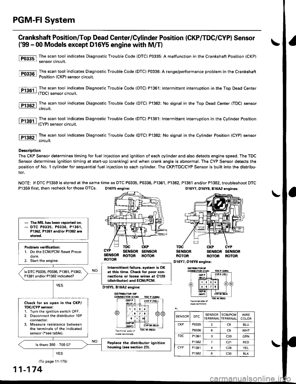
Crankshaft Position/Top Dead Center/Cylinder Position (CKP/TDC/CYPI Sensor
f99 - 00 Models except D16Y5 engine with M/T)
The scan tool indicates Diagnostic Trouble Code (DTC) P0335: A malfunction in the Crankshaft Position (CKP)
sensor circuit.
The scan tool indicates Diagnostic Trouble Code (DTC) P0336: A range/performance problem in the Crankshaft
Position (CKP) sensor circuit.
The scan tool indicates Diagnostic Trouble Code (DTC) P1361: Intermittent interruption in the Top Dead Center
{TDC) sensor circuit.
The scan tool indicates Diagnostic Trouble Code {DTC) P1362: No signal in the Top Dead Center (TDC) sensor
circuit.
The scan tool indicates Diagnostic Trouble Code (DTC) P1381: Intermittent interruption in the Cylinder Position(CYP) sensor circuit.
lTiaSt The scan tool indicates Diagnostic Trouble Code (DTC) P1382; No signal in the Cylinder Position (CYP) sensor: circuil.
DoscriDtion
The CKP Sensor determines timing for fuel injection and ignition of each cylinder and also detects engine speed. The TDC
Sensor determines ignition timing at start-up (cranking) and when crank angle is abnormal. The CYP Sensor detects the
position of No. 1 cylinder for sequential fuel injection to each cylinder. The CKP/TDC/CYP Sensor is built into the distribu-
tor.
NOTE; lf DTC P1359 is stored at the same time as DTC P0335, P0336, P1361. P1362, P1381 and/or P1382, troubleshoot DTC
P1359 first, then recheck for those DTCS. D16Y5 engino:
SENSORROTOR
TDGSENSORCKPSENSOBTDCSENSOBCKPSENSOBCYPs€NsonBOTORROTORBOTONROTOR ROTOR
D16Y7, D16Y8 ongine:
(To page 11-175)
1-174
- The MIL has been reportod on.- DTC P0335, P0336. P1361,P1362, P1381 rnd/or P1382.restored.
Problem verific{tion:1. Do the ECM/PCM Reset Proce-dure.2. Start the engine.
Intormittcnt failure, systom b OKat thb time. Check to. poor con-nections or loose wires at C120(dktributorl and ECM/PCM.
ls DTC P0335, P0336, P1361, P1362,P1381 and/or Pl382 indicated?
Check tor an open in the CKP/TDC/CYP 3enior:1. Turn the ignition switch OFF.2. Disconnect the distributor 10Pconnector,3. Measure resistance betweenthe terminals of the indicatedsensor (*see table).
Replrce the distributor ignitionhou3ing (!ee section 231.ls there 350 700 0?
SENSORDTCSENSORTEBMINAIECM/PCMTERI\,4INAICOLOR
CKPP0335
P0336
2c88LU
6c9
TDCP1361
P1362
3c20GRN
7c21BED
CYPP1381
P1342
c29YEL
Ic30BLK
Page 499 of 2189
Fuel Supply System
System Description
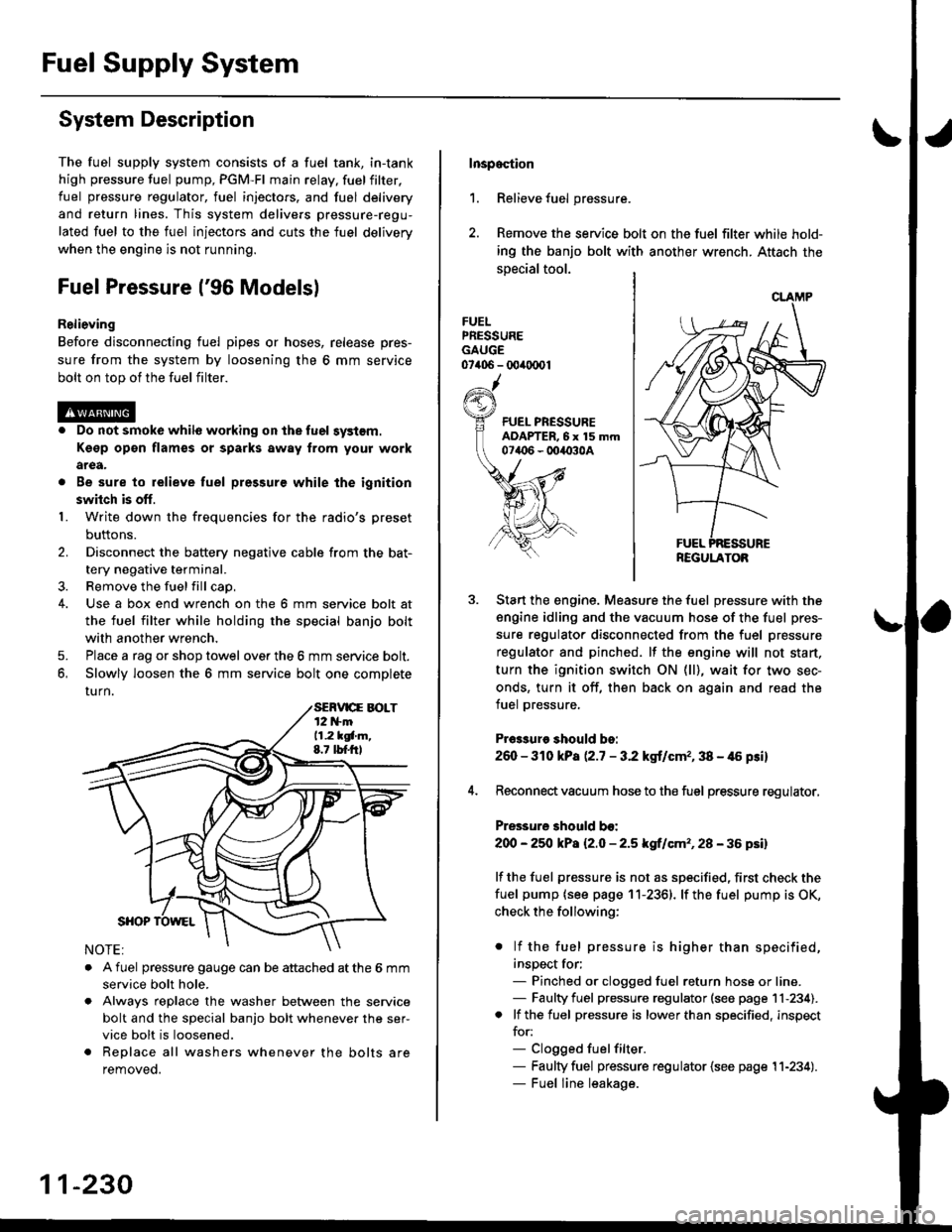
The fuel supply system consists of a fuel tank, in-tank
high pressure fuel pump, PGM-FI main relay, fuelfilter,
fuel pressure regulator, fuel injectors. and fuel delivery
and return lines. This system delivers pressure-regu-
lated fuel to the fuel injectors and cuts the fuel delivery
when the engine is not running.
Fuel Pressure l'96 Modelsl
Relieving
Before disconnecting fuel pipes or hoses, release pres-
sure from the system by loosening the 6 mm service
bolt on top of the fuel filter.
. Do not smoke whil6 working on the fuel system.
Kgsp opon flames or sparks away from youl work
area.
. Be sure to relieve fuel pressure while the ignition
switch is off.
1. Write down the frequencies for the radio's preset
buttons.
2. Disconnect the battery negative cable from the bat-
tery negative terminal.
3. Remove the fuelfill cap,
4. Use a box end wrench on the 6 mm service bolt at
the fuel filter while holding the special banjo bolt
with another wrench,
5. Place a rag or shop towel over the 6 mm service bolt.
6, Slowly loosen the 6 mm service bolt one complete
rurn.
. A fuel pressure gauge can be attached at the 6 mm
service bolt hole.
. Always reDlace the washer between the service
bolt and the special banjo bolt whenever the ser-
vice bolt is loosened.
. Replace all washers whenever the bolts are
removeo.
11-230
Inspoction
1. Relieve fuel pressure.
2. Remove the service bolt on the fuel filter while hold-
ing the banjo bolt with another wrench. Attach the
special tool.
FUELPRESSUREGAUGE07406 - 00ir0(x)1
Start the engine. Measure the fuel pressure with the
engine idling and the vacuum hose of the fuel pres-
sure regulator disconnected from the fuel pressure
regulator and pinched. lf the engine will not start,
turn the ignition switch ON (ll), wait for two sec-
onds, turn it off, then back on again and read the
fuel pressure.
Pr€3sure should bo:
260 - 310 kPa (2.7 - 3.2 kgt/cmr, 38 - 46 psi)
Reconnect vacuum hose to the fuel pressure regulator,
Pressure should bo:
200 - 25O kPa l2.O - 2.5 kgf/cm'�, 28 - 36 psil
lf the fuel pressure is not as specified, first check the
fuel pump {see page 11-2361. lf the fuel pump is OK,
check the following:
. lf the fuel pressure is higher than specified,
inspect for;- Pinched or clogged fuel return hose or line.- Faulty fuel pressure regulator (see page 11-234).. lf the fuel pressure is lower than specified, inspect
for:- Clogged fuelfilter.- Faulty fuel pressure regulator {see page 11-234).- Fuel line leakage.
REGULATOB
Page 500 of 2189
tJFuel Pressure {'97 and later Models)
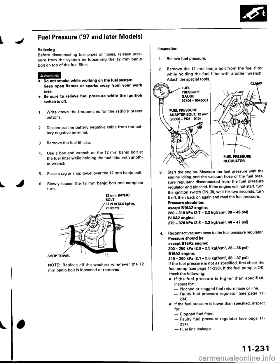
ReliGving
Before disconnecting tuel pipes or hoses, release pres-
sure from the system by loosening the 12 mm banjo
bolt on top of the fuel filter.
@o Do not smoke whilo working on the fuel sy3lom.
Ksgp op€n flames or sparks away tlom Your work
arga.
. Be sure to relieve fuel pressule while the ignition
swhch is off.
1. Write down the frequencies for the radio's preset
buttons,
2. Disconnect the battery negative cable from the bat-
tery negative terminal.
3. Remove the fuel fill cap.
Use a box end wrench on the 12 mm banjo bolt at
the fuel filter while holding the fuel filter with anoth-
er wrench.
Place a rag or shop towel over the 12 mm banio bolt.
Slowly loosen the 12 mm banjo bolt one complete
turn.
4.
I
12 mm BAtt OBOLT33 N.m (3.i1 kgf m,25 tbf.f0
NOTE: Replace all the washers whenever the 12
mm banio bolt is loosened or removed.
Inspaqtion
1. Relieve fuel pressure.
2. Remove the 12 mm banjo bolt from the fuel filter
while holding the fuel Jilter with another wrench
Attach the special tools.
3. Start the enginethe fuel Pressure with the
engine idling and the vacuum hose of the fuel pres-
sure regulator disconnected from the fuel pressure
regulator and pinched lfthe engine will not start, turn
the ignition switch ON {ll), wait for two seconds, turn
it off, then back on again and read the fuel pressure'
Pr$3uro ehould be:
excepi 816A2 sngine:
260 - 310 kPa {2'7 - 3.2 kgf/cm" 38 - {6 Fi}
B16A2 engine:
27O -32O kPa P.8 - 3'3 kgf/cm'�, '10 - 47 psi)
4. Reconnect vacuum hoso to the fuel pressure regulator'
Pre33ure 3hould be:
except B16A2 engin€:
2OO - 250 kPa {2.0 - 2'5 kgf/cm'�, 28 - 36 psi)
B16A2 engino:
210 - 260 kPa 121 - 2.6 ksf/cm'�, 30 - 37 psi)
lf the fuel pressure is not as specified, first check the
fuel pump (see page 11-236) lfthetuel pumpisoK,
check tho following:
. lf the fuel pressure is higher than specified,
inspect for:- Pinched or clogged fuel return hose or line.
- Faulty fuel pressure regulator (see page 11-
2341.
. lf the fuel pressure is lower than specified, inspect
for:- Clogged fuel filter.
- Faulty fuel pressure regulator (see page l1-
2341.- Fuel line leakage.
FUEL PRESSUREADAPTER BOLT, 12 mm
tguxt8-PD6-0101
CLAMP
REGULATOR
11-231
Page 543 of 2189
Emission Control System
Evaporative Emission (EVAP) Gontrols (cont'd)
'99 - 0O models only:
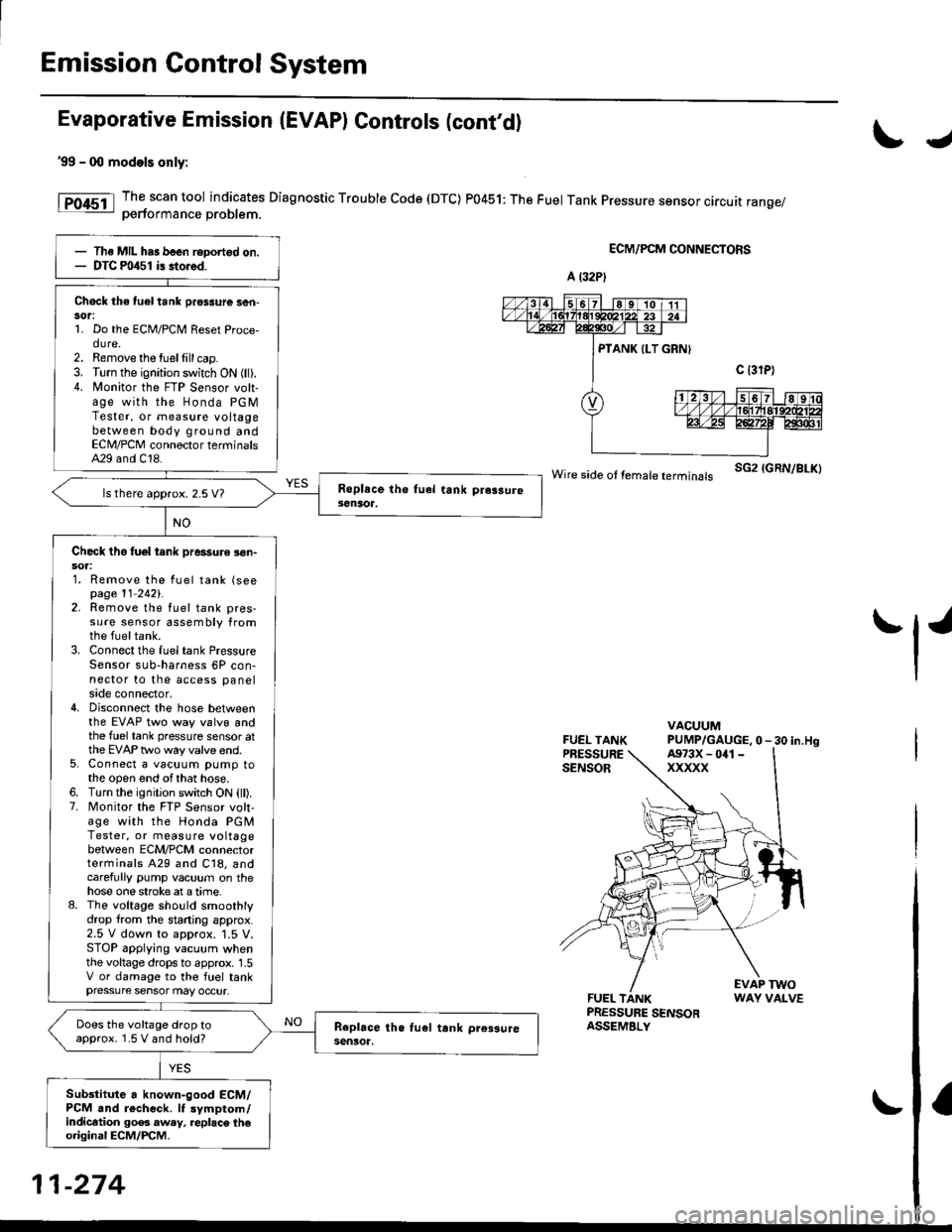
The scan tool indicates Diagnostic Trouble Code (DTC) P0451: The Fuel Tank Pressure sensor circuit range/oerformance Droblem.
ECM/PCM CONNECTORS
wire side ot femare terminars sG2 IGRN/BLK)
FUEL TANKPRESSURESENSOR
VACUUMPUMP/GAUGE,0 - 30 in.Hg
FUEL TANKPRESSURE SENSORASSEMBLY
EVAP TWOWAY VALVE
IJ
tl'
Ths MIL has been reDortgd on.DTC m/$1 i3 stored.
Check the tuel tank pros3ure ser|-sor:1. Do the ECM/PCM Reset Proce-dure.2. Remove the tuellill cap.3. Turn the ignition switch ON (ll).4. N4onitor the FTP Sensor volt-age with the Honda PGMTester, or measure voltagebetween body ground andECN4/PCM connector terminalsA29 and C18.
ls there approx. 2.5 V7
Check tho tuel tank pressure !on-soa:1. Remove the fuel tank (seepage 11 2421.2. Remove the fuel tank pres-sure sensor assembly fromthe fueltank.3. Connect the fuel tank PressureSensor sub-harness 6P con-nector to the access panelside connector,4. Disconnect the hose betweenthe EVAP two way valvg andthe fuel tank pressure sensor atthe EVAP two way valve end.5. Connect a vacuum pump tothe open end ofthat hose.6. Turn the ignition switch ON (ll).7. Monitor the FTP Sensor volt,age with the Honda PGMTester, or measure voltagebetween ECM/PCM connectorterminals A29 and C18, andcarefully pump vacuum on thehose one stroke at a time.8. The voltage sho!ld smoothlydrop from the stading approx.2.5 V down to approx. '1.5 V.STOP applying vacuum whenthe voltage drops to approx. 1.5V or damage to the fuel tankpressure sensor may occur.
Does the voltage drop toapprox. 1.5 V and hold?
Sub3titute a known-good ECM/PCM and r6check. It symptom/indicltion 90e3 aw.y, replac\. th€original ECM/PCM.
A (32P)
A973X - 041 -
xxxxx
11-274