Seat frame HONDA CIVIC 1997 6.G Workshop Manual
[x] Cancel search | Manufacturer: HONDA, Model Year: 1997, Model line: CIVIC, Model: HONDA CIVIC 1997 6.GPages: 2189, PDF Size: 69.39 MB
Page 1143 of 2189
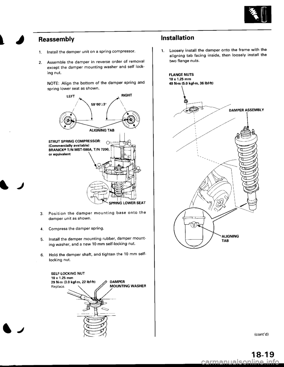
\Reassembly
2.
't.
lr
Install the damper unit on a spring compressor.
Assemble the damper in reverse order of removal
except the damper mounting washer and self lock-
ing nut.
NOTE: Align the bottom of the damper spring and
spring lower seat as shown.
STRUTSPRING COMPRESSOR:
lcommercially availablelBRANICK@ T/N MST.58OA, T/N 7200,
or 6quival€nt
SPBING LOWER SEAT
Position the damper mounting base onto the
damper unit as shown.
Compress the damPer sPring.
Install the damper mounting rubber, damper mount-
ing washer, and a new 10 mm self-locking nut.
Hold the damper shaft. and tighten the 10 mm self-
locking nut.
SELF-LOCKING NUT10 x 1.25 mm29 N.m 13.0 kgf m, 22 lbf ft)
3.
4.
Replace.
DAMPERMOUNTING WASHER
(l-t
lnstallation
1. Loosely install the damper onto the frame with the
aligning tab facing inside. then loosely install the
two flange nuts.
FLANGE NUTS10 x 1 ,25 mm49 N.m (5.0 kgt'm, 36 lbf'ftl
DAMPER ASSEMBLY
{cont'd)
18-19
Page 1231 of 2189
l}
e\
Body ('96 modell
Doors
Front Door Index (4D) ...20-2
Rear Door Index {4Dl .....20-8
Door fndex lzDl3Dl .......20-14
Emblems
f nstallation 20-118
Exterior
Component Location Index ............... 20-93
*Frame Repair Chart .......... 20-120
* Interior
Component Location Index ............... 20-58
Mirrors
Mirror Rep|acement .................. ......... 20-24
Mirror Holder/Gover Replacement ... 20-25
Rearview Mirror Reolacement .......... 20-25
Moonroof
lndex .......... .....................20-50
Opener Cable/Opener and Latch/
Wiper and Washer
Component Location Index .......... ...,. 20-107
Seats and Seat Belts
Gomponent Location Index .......... ..... 20-73
Sub-frame ....20-119
Windshield, Rear Window and Ouarter Glass
Index .......... .....................20-26
Body {'97 modell
Body ('98 modell
Body ('99 modell
Body ('00 model)
20-123
20-131
20-135
20-141
It
Page 1284 of 2189
Moonroof
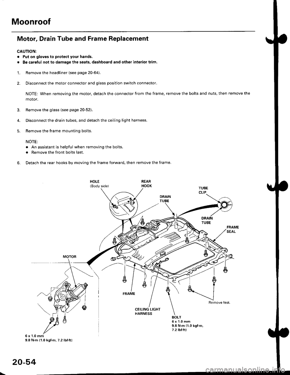
Motor, Drain Tube and Frame Replacement
CAUTION:
. Put on gloves to protecl your hands.
. Be careful not to damage the seats, dashboard and other interior trim.
'1. Remove the headliner {see page 20-64).
2. Disconnect the motor connector and glass position switch connector.
NOTE: When removing the motor, detach the connector from the frame, remove the bolts and nuts, then remove the
motor.
3. Remove the glass {see page 20-52).
4. Disconnect the drain tubes, and detach the ceiling light harness.
5. Remove the frame mounting bolts.
NOTE;
. An assistant is helpful when removing the bolts.
. Remove the front bolts last.
6. Detach the rear hooks by moving the frame forward, then remove the frame.
BOLT6x1.0mm9.8 N.m {1.0 kgt m,7.2 tht.hl
6x1.0mm9.8 N m (1.0 kgl.m, 7.2 lbtft)
20-54
\
Page 1307 of 2189
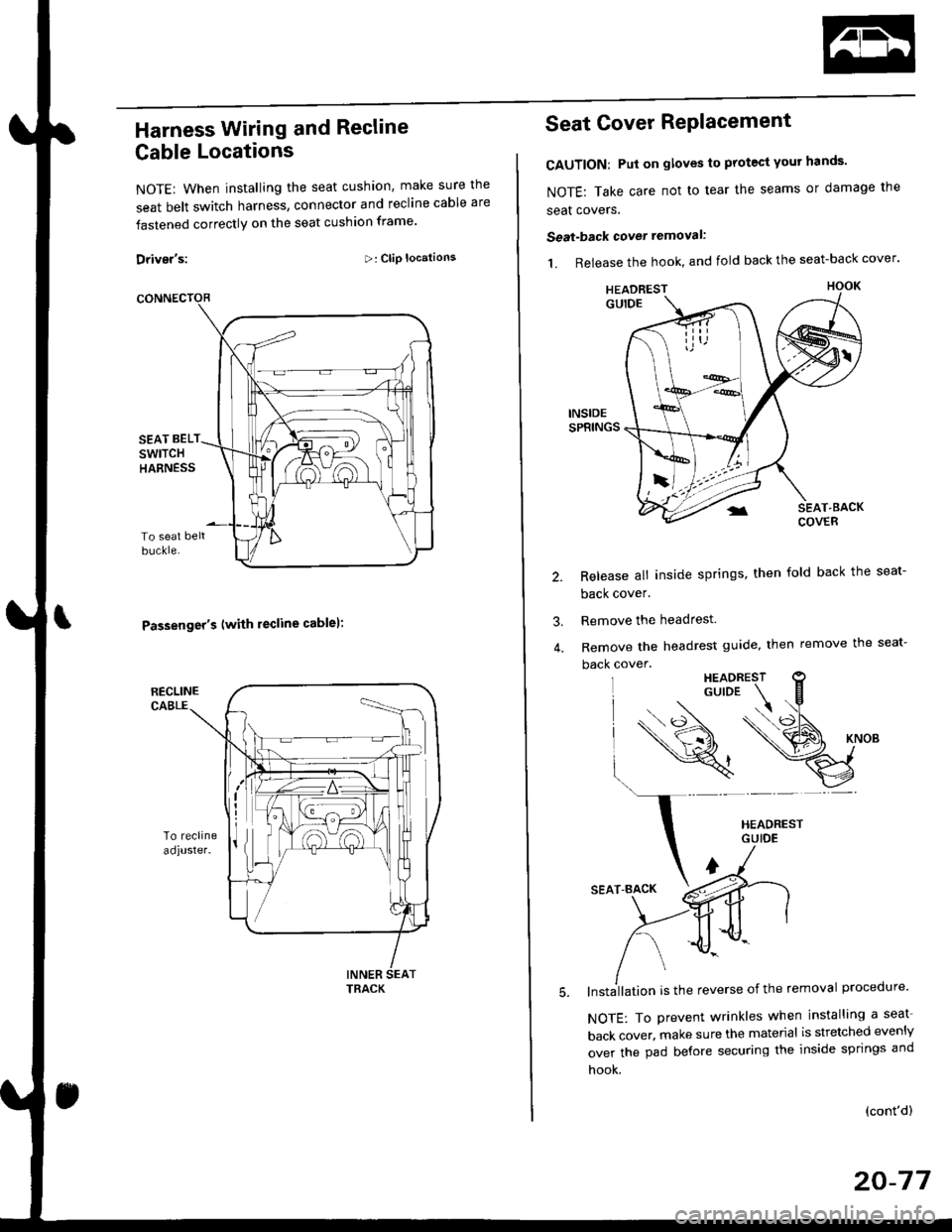
Harness Wiring and Recline
Cable Locations
NOTE: When installing the seat cushion, make sure the
seat belt switch harness, connector and recline cable are
fastened correctly on the seat cushion frame'
Driver's:>: Clip locations
Passenger's (with lecline cablel:
TRACK
Seat Cover RePlacement
CAUTION: Put on gloves to protest yout hands'
NOTE: Take care not to tear the seams or damage the
seat covers.
Seat-back cover removal:
1. Release the hook, and fold back the seat-back cover'
Release all inside springs, then fold back the seat-
back cover.
Remove the headrest.
Remove the headrest guide, then remove the seat-
back cover.
lnst;llation is the reverse of the removal procedure'
NOTE: To prevent wrinkles when installing a seat-
back cover, make sure the material is stretched evenly
over the pad before securing the inside springs and
hook.
3.
(cont'd)
20-77
HEADREST
Page 1308 of 2189
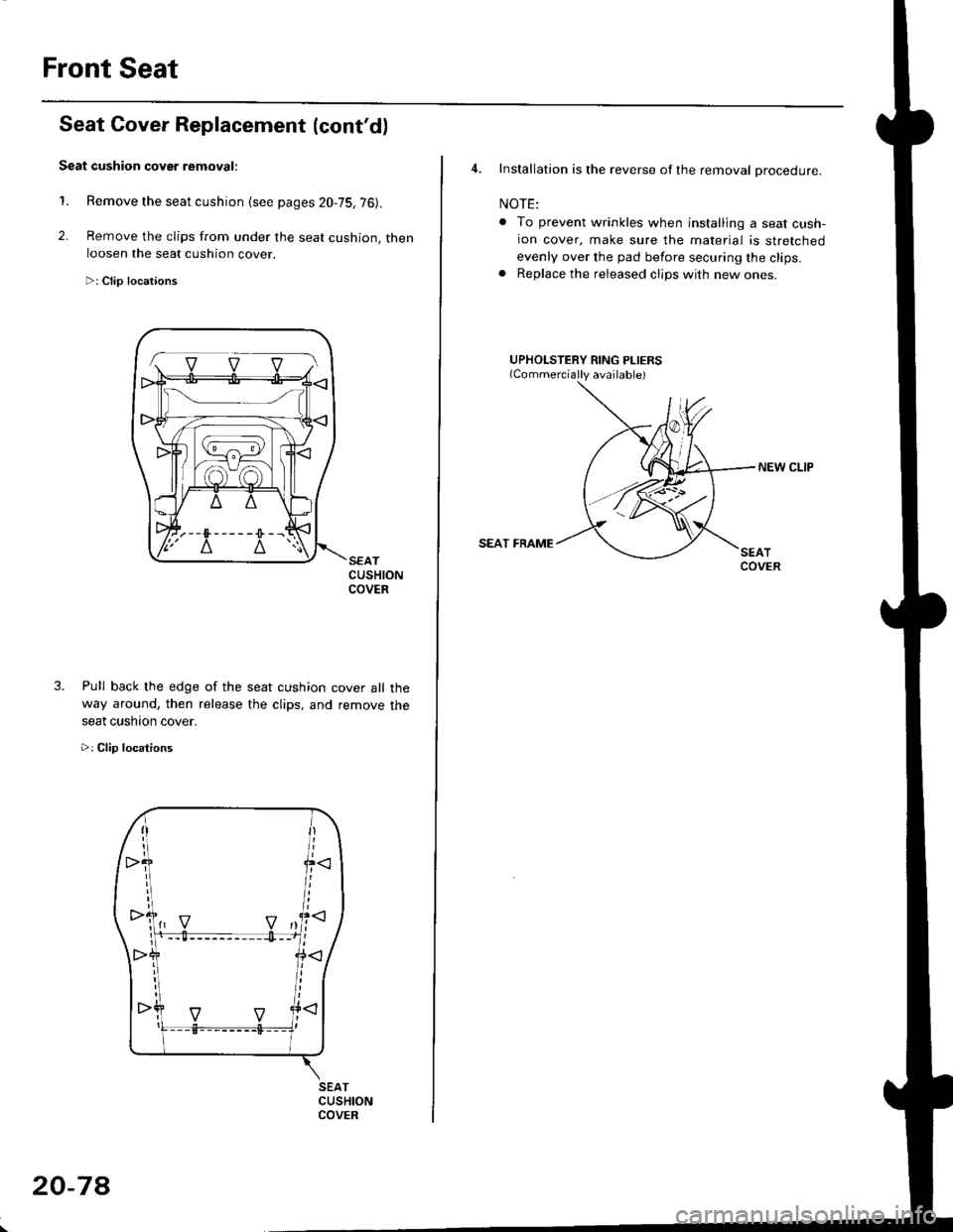
Front Seat
2.
1.
3.
CUSHIONCOVER
cover all the
remove the
Seat Cover Replacement (cont'd)
Seat cushion cover removal:
Remove the seat cushion {see pages 20,75,76).
Remove the clips from under the seat cushion, thenloosen the seat cushion cover.
>: Clip locataons
Pull back lhe edge of the seat cushion
way around, then release the clips, and
seat cushaon cover.
>: Clip locations
SEATCUSHIONCOVER
1-. v v vl
20-7A
4. Installation is the reverse of the removal procedure.
NOTE:
. To prevent wrinkles when installing a seat cush-ion cover, make sure the material is stretched
evenly over the pad before securing the clips.. Replace the released clips with new ones.
UPHOLSTERY RING PLIERS
NEW CLIP
SEAT FRAME
Page 1314 of 2189
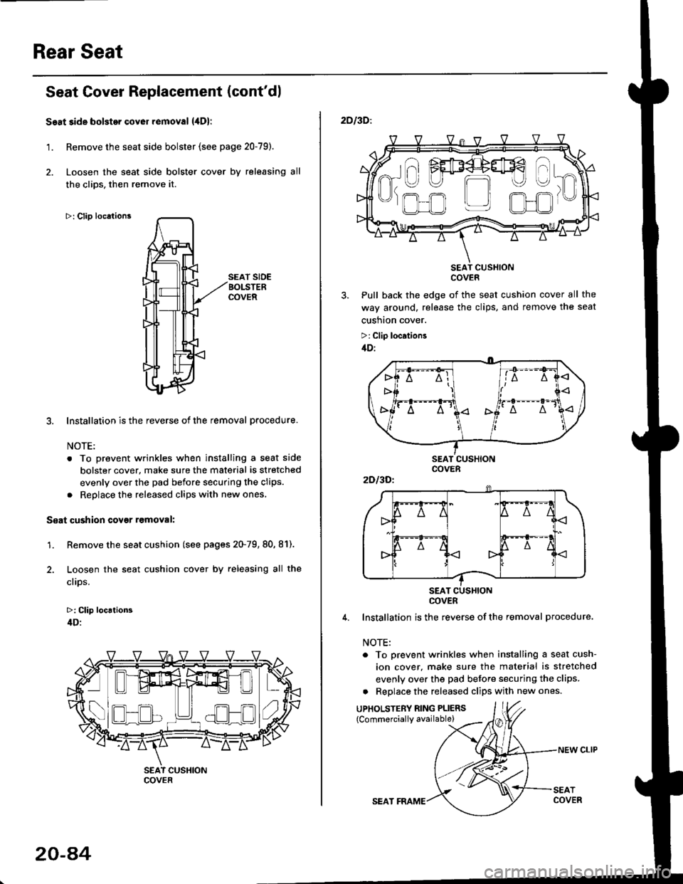
Rear Seat
Seat Cover Replacement (cont'dl
Seat side bolstor cover removal {,lDl
1. Remove the seat side bolster (see page 20-79).
2. Loosen the seat side bolster cover by releasing all
the clios, then remove it.
>: Clip locations
SEAT SIDEBOLSTERCOVER
3. Installation is the reverse of the removal procedure.
NOTE:
. To prevent wrinkles when installing a seat side
bolster cover, make sure the material is stretched
evenly over the pad before securing the clips.
. Reolace the released cliDs with new ones,
S€at cushion covgr r6moval:
1. Remove the seat cushion (see pages 20-79, 80, 81).
2. Loosen the seat cushion cover by releasing all the
clips.
>: Clip locrtion3
4D:
- -I ./al--lt___)l ) ( .)Ll!!l^t!!l 1",
COVER
20-a4
SEAT FRAME
NEW CLIP
2DI3D:.
SEAT CUSXIONCOVER
Pull back the edge of the seat cushion cover all the
way around, release the clips, and remove the seat
cusnton cover.
>: Clip location3
/tD:
4. Installation is the reverse ofthe removal procedure.
NOTE:
. To prevent wrinkles when installing a seat cush-
ion cover. make sure the material is stretched
evenly over the pad before securing the clips.
a Replace the released clips with new ones.
UPHOLSTERY RING PLIERS
{Commerciallv available)
a\
------)
t" I FEF4+#€
R-U U m
'J)
,.ofl r_r olJr
2Dl3Dl
COVER
Page 1368 of 2189
Reassemble in the reverse order of disassembly' and
note these items:
. Make sure the bushing and pivot washer are installed
properly.
. To connect the connecting wire, twist it 90'.
. Replace the back cover clips with new ones
. To prevent wrinkles when installing the seat-back
cover, make sure the material is stretched evenly
over the pad.
. Apply multipurpose grease to the moving portion of
the seat track.
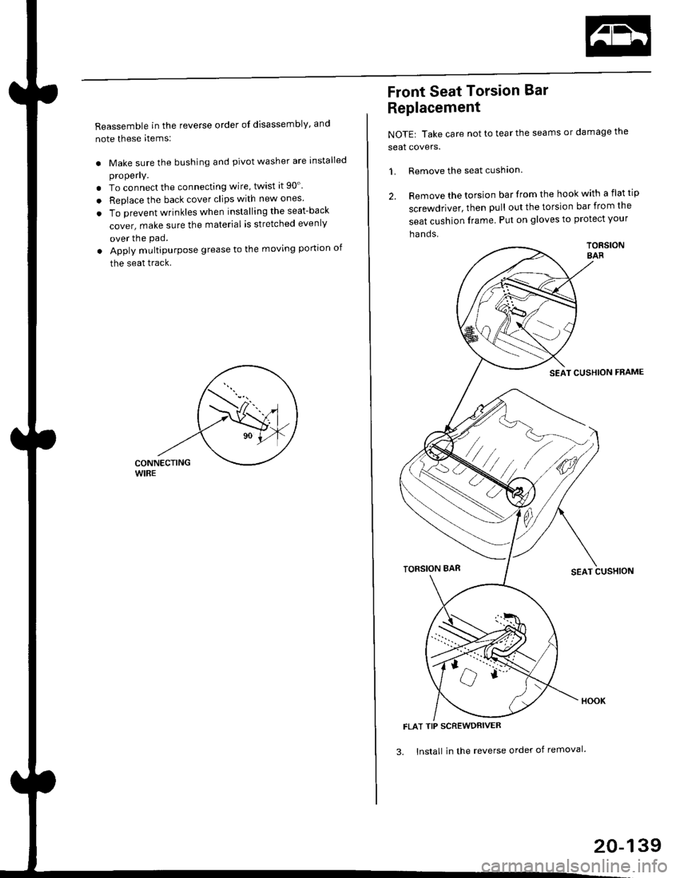
Front Seat Torsion Bar
Replacement
NOTE| Take care not to tear the seams or damage the
seat covers.
1. Remove the seat cushlon
2. Remove the torsion bar from the hook with a flat tip
screwdriver, then pull out the torsion bar from the
seat cushion frame Put on gloves to protect your
ha nds.
TORSIONSAR
SEAT CUSHION FNAME
TORSION BARSEAT CUSHION
FLAT TIP SCREWDRIVER
3. lnstall in the reverse order of removal'
20-139
Page 1474 of 2189
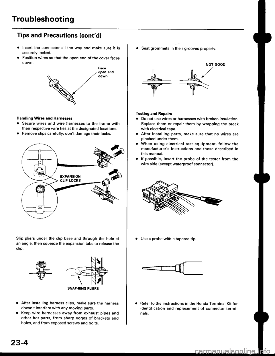
Troubleshooting
Tips and Precautions (cont'dl
Insert the connector all the way and make sure it is
securelv locked.
Position wires so that the open end of the cover faces
down.
After installing harness clips, make sure the harness
doesn't interfere with any moving pans.
Keep wire harnesses away from exhaust pipes and
other hot parts. from sharp edges of brackets and
holes, and from exDosed screws and bolts.
V
F6c6op€n end
Handling Wires and Harnosscs
. Secure wires and wire harnesses to the frame with
their respective wire ties at the designated locations,
. Remove clips carefully; don't damage their locks.
Slip pliers under the clip base and through the hole at
an angle, then squeeze the expansion tabs to release the
clrp.
SNAP-BING PLIERS
23-4
NOT GOOO
ll il,/
s*' -.1}8."/_Y--_Y5\
il ,,
Testing and Repairs
o Do not use wires or harnesses with broken insulation.
Replace them or repair them by wrspping the break
with electricaltaoe.
. After installing parts, make sure that no wires arepinched under them.. When using electrical test equipment, follow the
manufacturer's instructions and those described in
this manual.
. lf possible, insert the probe of the tester from the
wire side (except waterproof connector).
. Seat grommets in their grooves properly.
. Use a probe with a tapered tip.
Refer to the instructions in the Honda Terminal Kit for
identification and replacement of connector termi-
nats.