electrical HONDA CIVIC 1998 6.G Workshop Manual
[x] Cancel search | Manufacturer: HONDA, Model Year: 1998, Model line: CIVIC, Model: HONDA CIVIC 1998 6.GPages: 2189, PDF Size: 69.39 MB
Page 1474 of 2189
Troubleshooting
Tips and Precautions (cont'dl
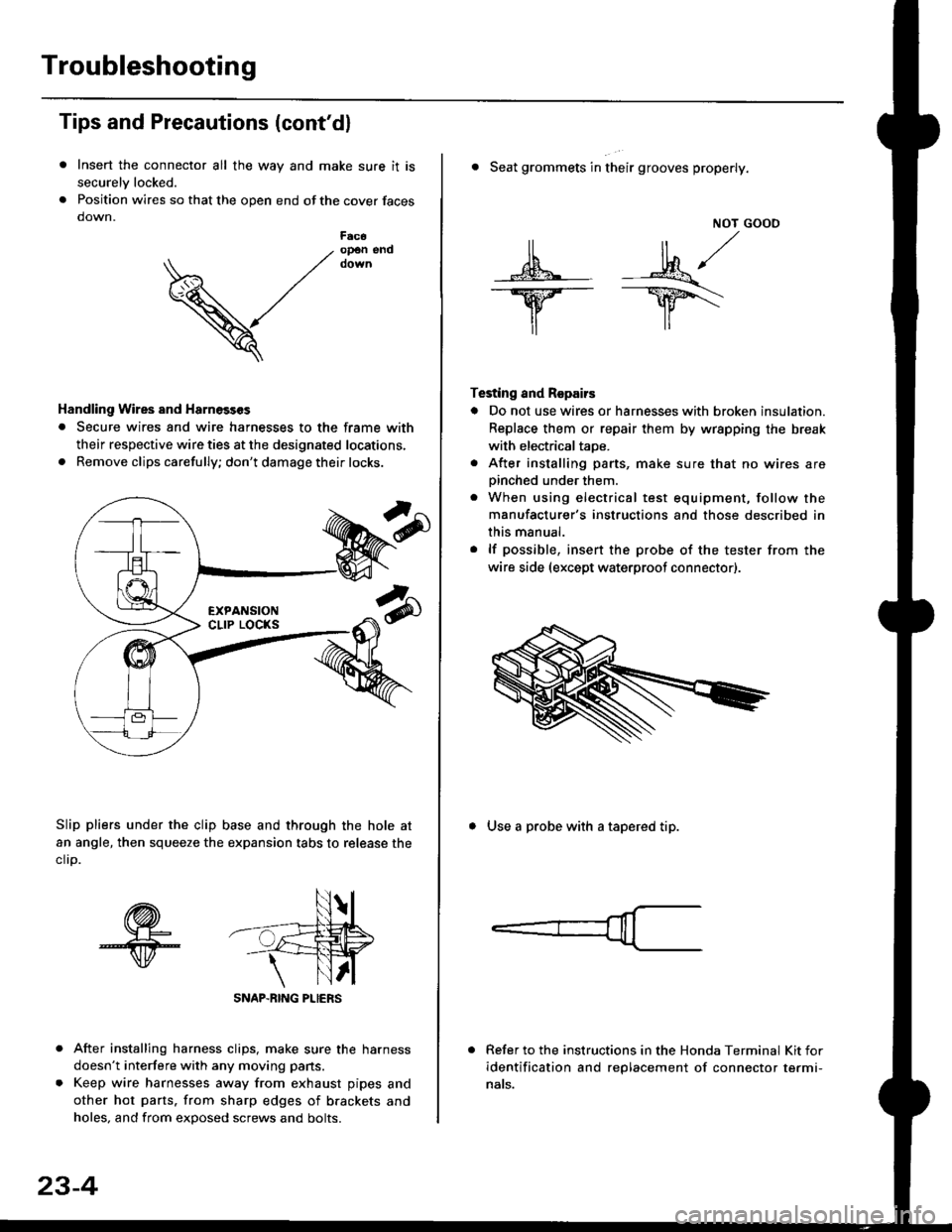
Insert the connector all the way and make sure it is
securelv locked.
Position wires so that the open end of the cover faces
down.
After installing harness clips, make sure the harness
doesn't interfere with any moving pans.
Keep wire harnesses away from exhaust pipes and
other hot parts. from sharp edges of brackets and
holes, and from exDosed screws and bolts.
V
F6c6op€n end
Handling Wires and Harnosscs
. Secure wires and wire harnesses to the frame with
their respective wire ties at the designated locations,
. Remove clips carefully; don't damage their locks.
Slip pliers under the clip base and through the hole at
an angle, then squeeze the expansion tabs to release the
clrp.
SNAP-BING PLIERS
23-4
NOT GOOO
ll il,/
s*' -.1}8."/_Y--_Y5\
il ,,
Testing and Repairs
o Do not use wires or harnesses with broken insulation.
Replace them or repair them by wrspping the break
with electricaltaoe.
. After installing parts, make sure that no wires arepinched under them.. When using electrical test equipment, follow the
manufacturer's instructions and those described in
this manual.
. lf possible, insert the probe of the tester from the
wire side (except waterproof connector).
. Seat grommets in their grooves properly.
. Use a probe with a tapered tip.
Refer to the instructions in the Honda Terminal Kit for
identification and replacement of connector termi-
nats.
Page 1559 of 2189
lgnition Switch
4.
Test
SRS components are located in this area Review the
SRS component locations. precautions. and procedures
in the SRS section {24} before performing repairs or ser-
1. i/ake sure you have the anti-theft code for the
radio, then write down the frequencies for the
radio's preset buttons ('99 - 00 models).
2. Disconnect the battery negative cable.
3. Remove the driver's dashboard lower cover and
knee bolster (see section 20).
Disconnect the 5P connector from the under dash
fuse/relay box and the 7P connector from the main
wire harness.
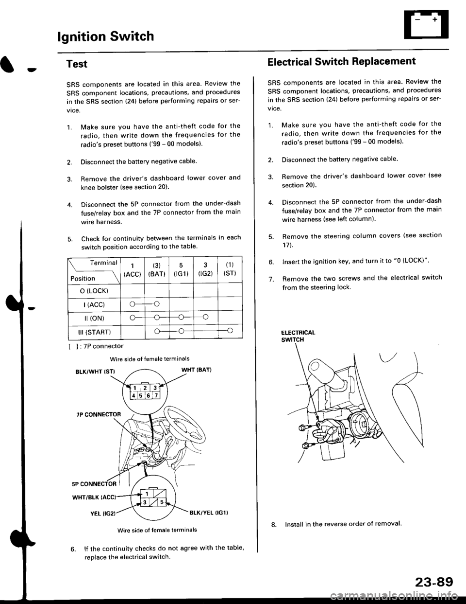
Check for continuity between the terminals in each
switch position according to the table.
I I :7P connector
Wire side ot female terminals
BLK/WHT {STIWHT IBAT}
7P CONNECTOR
WHT/BLK
YEL (IG2}BLK/YEL {IG1)
Wire side of female terminals
6. lf the continuity checks do not agree with the table,
replace the electrical switch.
Terminal
Position
1
(ACC)
(3)
(BAT)
5
{tG1) G2)
(1)
(sr)
o (LocK)
| (ACC)o--o
l (oN)o-o
III (START)o--o
1.
Electrical Switch RePlacement
SRS components are located in this area. Review the
SRS component locations, precautions, and procedures
in the SRS section \24) belore performing repairs or ser-
vtce.
1. Make sure you have the anti-theft code for the
radio, then write down the frequencies for the
radio's preset buttons {'99 - 00 modelsl.
2. Disconnect the battery negatlve cable.
3. Remove the driver's dashboard lower cover {see
section 20).
Disconnect the 5P connector from the under-dash
fuse/relay box and the 7P connector from the main
wire harness (see left column).
Remove the steering column covers {see section
11t.
lnsert the ignition key, and turn it to "0 {LOCK)".
Remove the two screws and the electrical switch
from the steering lock.
ELECTRICALswtTcH
8. Install in the reverse order of removal.
23-a9
Page 1582 of 2189
Charging System
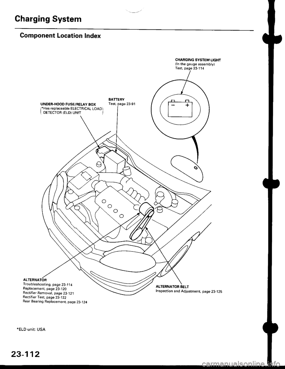
Component Location Index
UNDER.HOOD FUSE/RELAY BOX/*Has replaceable ELECTRICAL LOAD II DETECTOR (ELD) UNIT '
Troubleshooting, page 23-1 14Replacement, page 23-120Bectifier Removal, page 23,121Rectifier Test, page 23-122Rear Bearing Replacement, page 23-j24
*ELD unit: USA
CHARGING SYSTEM LIGHT(ln the gauge assembly)Test, page 23- l14
BATTERYTest, page 23-91
ALTERNATOR BELTInspection and Adjustment, page 23-t25
[]
23-112
Page 1589 of 2189
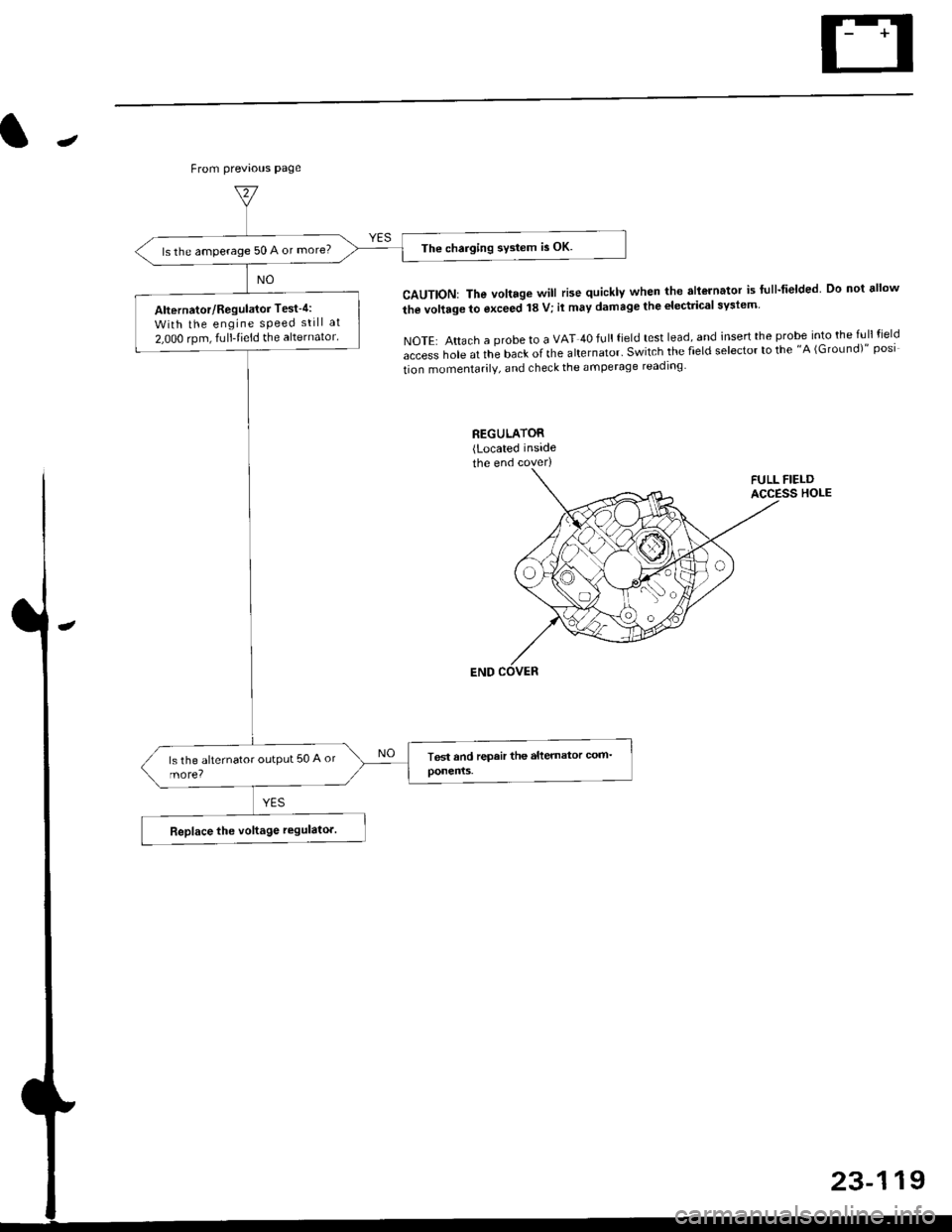
The charging system is OK.ls the amperage 50 A or more?
Alternator/Regulator Test-4:
With the engine sPeed still at
2,000 rpm, fulltieid the alternator.
J
From previous page
CAUTION: The voltage will rise quickly when the allGrnator is flll-fielded Do not ellow
the vollage to exceed 18 V; il may damage the electrical syslem
NOTE: Attach a probe to a VAT 40 full field test lead, and insert the probe into the full field
access hole at the back of the alternator' Switch the field selector to the "A (GroLrnd)" posi
tion momentarilV, and check the amperage readlng
23-119
Page 1745 of 2189
Precautions/ Procedures
)General Precautions
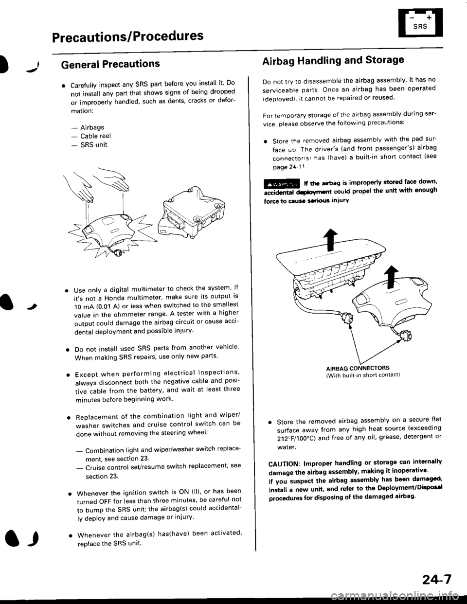
r Carefully inspect any SRS part before you install it Do
not install any part that shows signs of being dropped
or improperly handled' such as dents, cracks or defor-
mation:
- Airbags- Cable reel
- SRS unit
-
Use only a digital multimeter to check the system lf
it's not a Honda multimeter, make sure its output ls
1O mA (0.01 A) or less when switched to the smallest
value in the ohmmeter range. A tester with a higher
output could damage the airbag circuit or cause acci-
dental deployment and possible injury'
I Do not install used SRS parts from another vehicle
When making SRS repairs, use only new pans'
) Except when performing electrical inspections'
always disconnect both the negative cable and posl-
tive cable from the battery, and wait at least three
minutes before beginning work
r Replacement of the combination light and wiper/
washer switches and cruise control switch can be
done without removing the steering wheel:
- Combinalion light and wiper/washer switch replace
ment, see section 23
- Cruise control sevresume switch replacement' see
section 23.
. Whenever the ignition switch is ON {ll), or has been
turned OFF for less than three minutes' be careful not
to bump the SRS unit; the airbag(s) could accidental-
ly deploy and cause damage or injury'
. Whenever the airbag{s) has(have) been activated'
replace the SRS unit.l,
2+7
Airbag Handling and Storage
Do not try to disassemble the airbag assembly. lt has no
serviceable parts Once an airbag has been operated
(deployed). it cannot be repaired or reused'
For temporary storage of the airbag assembly during ser-
vice. olease observe the following precauttons:
. store the .emoved airbag assemblv with the pad sur-
face uo The driver's (and front passenger's) airbag
connecto''s'-as {have) a built.in short contact (see
page 2a-l 1
: | ..r r-+r-a k imninncrlv slorcd lace down,-""dd.r6t dtatltt-,tl could propel the unit whh enough
force lo c.usa 3a.ix! intury
AIRBAG CONNECTORS(With built in shon contact)
. Store the removed airbag assembly on a secure flat
surface away from any high heat source {exceeding
212"FI1OO"CJ and free of any oil' grease, detergent or
water.
CAUTION: lmproper handling or storage can intern'lJy
damage the airbag assembly, making it inoperativo
lf you suspect the airbag assembly has been dam€cd'
inslall a new unit. and relsr lo the Deployment/DisPG'l
olocedules for disposing ol the damaged airbag
Page 1818 of 2189
How To Use This Manual
The next few pages describe how this manual is organized. They also
explain what kind of information the manual contains, what that
informalion means, and how to use it to troubleshoot electrical problems.
Circuit schematics break the entire electrical system into individual
systems, like the Low Fuel lndicator Light on the nelit page.
Only electrical components that work together are shown together,
so you won't be distracted by unrelated wires.
Explanations of the abbreviations and svmbols used in the schematics
begin on page [Fl. You'll need to know what they mean before you can use
a schematic effectively.
Page 1830 of 2189
Troubleshooting Tests
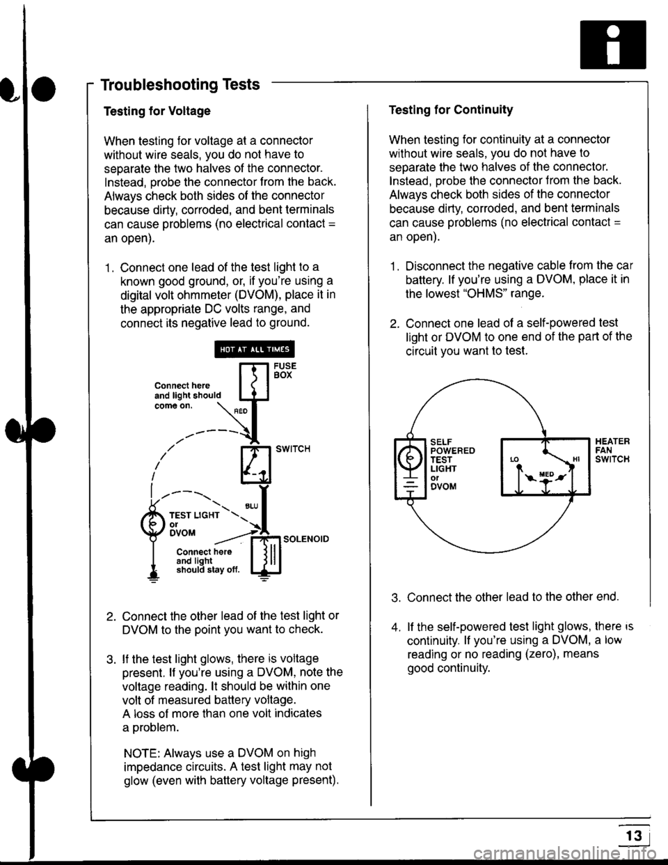
Testing for Voltage
When testing for voltage at a connector
without wire seals, you do not have to
seoarate the two halves of the connector.
Instead, probe the connector from the back.
Always check both sides of the connector
because dirty, corroded, and bent terminals
can cause problems (no electrical contact =
an open).
1 . Connect one lead of the test light to a
known good ground, or, if you're using a
digital volt ohmmeter (DVOM), place it in
the appropriate DC volts range, and
connect its negative lead to ground.
Connect the other lead of the test light or
DVOM to the point you want to check.
lf the test light glows, there is voltage
present. lf you're using a DVOM, note the
voltage reading. lt should be within one
volt of measured battery voltage.
A loss of more than one volt indicates
a problem.
NOTE: Always use a DVOM on high
impedance circuits. A test light may not
glow (even with baftery voltage present).
connecthere [fl5tst-tand light should IJJcomeon.
\" I
------{
/' BT swrrcH
lhl
l ----., I
6m""*soLENo,DI connect here I { lll
I 3#Ji8iL,* lj!!J
Testing for Continuity
When testing for continuity at a connector
without wire seals, you do not have to
separate the two halves of the connector.
lnstead. Drobe the connector Jrom the back.
Always check both sides of the connector
because dirty, conoded, and bent terminals
can cause problems (no electrical contacl =
an open).
1. Disconnect the negative cable from the car
battery. lf you're using a DVOM, place it in
the lowest "OHMS" range.
2. Connect one lead of a self-powered test
light or DVOM to one end of the part of the
circuit vou want lo test.
Connect the other lead to the other end.
lf the self-powered test light glows, there is
continuity. lf you're using a DVOM, a low
reading or no reading (zero), means
good continuity.
.t.
A
r3
Page 1842 of 2189
Power Distribution
- From Battery to lgnition Switch, Fuses, and Relays
STARTERPage 21,21-1, ot 21-2
.d1.ro"rr" i
I lsoLENorD I
FUSE 42tG1
BATTERY
To UndeFhood ABSFuse/RelayBox onpage 10-14.
FUSE 47EACK UP
T1
FUSE 41AATTEiY&A
I OETECTOR (ELD) UNIT
tii::.':
UO
PHOfO U
,
I
I
I
t.------J
ELECTRICAL LOAD
i--i rL---- J ELKml
!" Gl
FUSE 4e
0ro{ Urod)FUSE '13Ir|]EAtOAUGHT?.:ta
FUSE 46POWEaWll'IDOW
FUSE /t4
r| E/M1{rA204 (DrGa5)
FUS€ 48TtEADL|a}fT9|'A
FUSE 50NEAAOEFOCGER304
+------, f| ',
I ruse sr I oooa I
J LOC|( uNrr \
il-.4WHT/BLK
Itr '\
\
I
I
I
c352
vlEW 27
c415Se€ Pow€r Distribution,pag6s 10-10 and 10-11.See Power Distribution,page 10-12.
I
\
L------BLK/VI/HT
1
--------Jc415
Vehiclespre-wired foraccessorysecuritysystem
c913PHOTO 6A
FUSE 16AR DEFFEIAY
FUSE 17HEATEA!'/C FEIAY
FUSE 18{RUNNINOL|GHlFET.AY)7.54
FUSE 27CIGAFETTEL|oHTEAACC SOCKET ta
arse ra fBADIO \
?o?"* \15A ('94 raodcr)
ff".acc0)
llL--------J
See Power Distribution,pages 10-8 and 10-9.
STARTERCUT RELAYPage 21-2
P/lolo 135 (99 00)
See PowetDistribution,page 10-7.
Vehicles pre-wired for acces-sory security system
To Fuse 3'|, for delails, see StartrnqSystem, page 21,21-1 , ot 21-2. -
10
Page 1875 of 2189
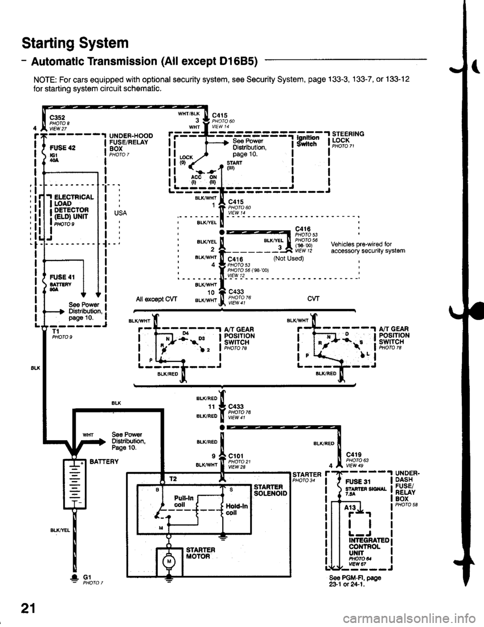
- Automatic Transmission (All except Dl685)
NOTE: For cars equipped with optional security system, see Security System, page 133-3, .133-7, or 133-12
for starting system circuit schomatic.
Starting System
c3s2PHO|O IvlEw 27
ftxiE "2E1404
WHT/BLK
I
lta":
c415
=-mF,Uf.
--l
9,lLT i ld;f,,"-
I
I
It
I
I
I
I
I
I
I
I
pag€ 10.
slan?(ll)
c415
I
Ji.I ELECTRICALI roAoI DETECTOR
I Gt ol ulra Ptfifo I
IJ
BLKAIVHT1
ELK./YEL
au(|vEL
BL'(4I/HT
4
c416PHOTO 53
c4t 6PHO|O 53PHO|O 56 f98 '�oo)vtEw t2
c433
Vehiclss pre-wired foraccessory securaty system(Not Used)
R'SE 4IlA??tNY,olALXAVHY'10
Allsxcsptow aLKlvHrcwSoe Pow6r IDistibution, !page 10. a- ----JT1PHOTO 9
BATTERY
BLKAVHT
7
L-----L---JBLKFED
13:;-1ifl;ft?R
!-
)2 'lPHoto tg
a
BLI(RED
1I
ELIVBED
ALKNED
c433PHOTO 76
Soe PowrDslributbn,Pa€o 10.
9 a c101
er.xiwxr I ffo,rtfl'�t
c4rIPHO|O 63
Ft gg 3r5? F En 3E ^r7.94
4
r'STARTERPHO|O 34UNDER.DASHFUSE/RELAYBOX
A13
tl
II{TEGRATEDco|{TnoLUT{ITPHOfOUvtEw 67,--==--J
Sso PGM-FI, page&1 ot 24-1.
21
lGl
Page 1876 of 2189
![HONDA CIVIC 1998 6.G Workshop Manual - Automatic Transmission (D1685)
c352
vtEw27
FUSE 42tGtao
.I ELECTRICALI LOADr DETECIOn
| (ELD) uNtrI PHOTO 9
I
UNDER.HOOOFUSE/RELAYBOX
r=-----L-_-_-_-_-_-=_-_-Tl.*1"","1#"Ei]""
li F 3,"j,[,ul
WHT/BL HONDA CIVIC 1998 6.G Workshop Manual - Automatic Transmission (D1685)
c352
vtEw27
FUSE 42tGtao
.I ELECTRICALI LOADr DETECIOn
| (ELD) uNtrI PHOTO 9
I
UNDER.HOOOFUSE/RELAYBOX
r=-----L-_-_-_-_-_-=_-_-Tl.*1"","1#"Ei]""
li F 3,"j,[,ul
WHT/BL](/img/13/6068/w960_6068-1875.png)
- Automatic Transmission (D1685)
c352
vtEw27
FUSE 42tGtao
.I ELECTRICALI LOADr DETECIOn
| (ELD) uNtrI PHOTO 9
I
UNDER.HOOOFUSE/RELAYBOX
r=-----L-_-_-_-_-_-=_-_-Tl.*1"","1#"Ei]""
li F 3,"j,[',ul
WHT/BLK
. J 9,1'3.WHt a V|EW 14
tcx,^ ) Page 10'
PHOTO 76
1--*---''!N"t- \o3bz7
See PowerDistribution,page 10.
c433
ALKRED4
r-^==.1
Stadorcontrol
POWERTRAINCONTROLMODULE (PCM)
c101
vtEw 28
ll
"'{----1iLi.' | |
Li-gl{l======i---i
"i*-iIr-m'
:il
See PowerDistribdion,Page '10.
".u,"if---'
-,*! s#;:{"
BLKAVHT N V/EW a t
STARTERCUTFELAYPHO|O 129
(99100)
A"/T GEARPOStTtONswrTcH
See PGlr-Fl,page 25.
STARTER
c419
FUSE 31STAffER Src{AI7.54
UNDER-DASHFUSE/NELAYBOX
BLKREO
11
"'-";;tr
A't 3
BATTERY
21-1