Under dash HONDA CIVIC 1998 6.G Workshop Manual
[x] Cancel search | Manufacturer: HONDA, Model Year: 1998, Model line: CIVIC, Model: HONDA CIVIC 1998 6.GPages: 2189, PDF Size: 69.39 MB
Page 1651 of 2189
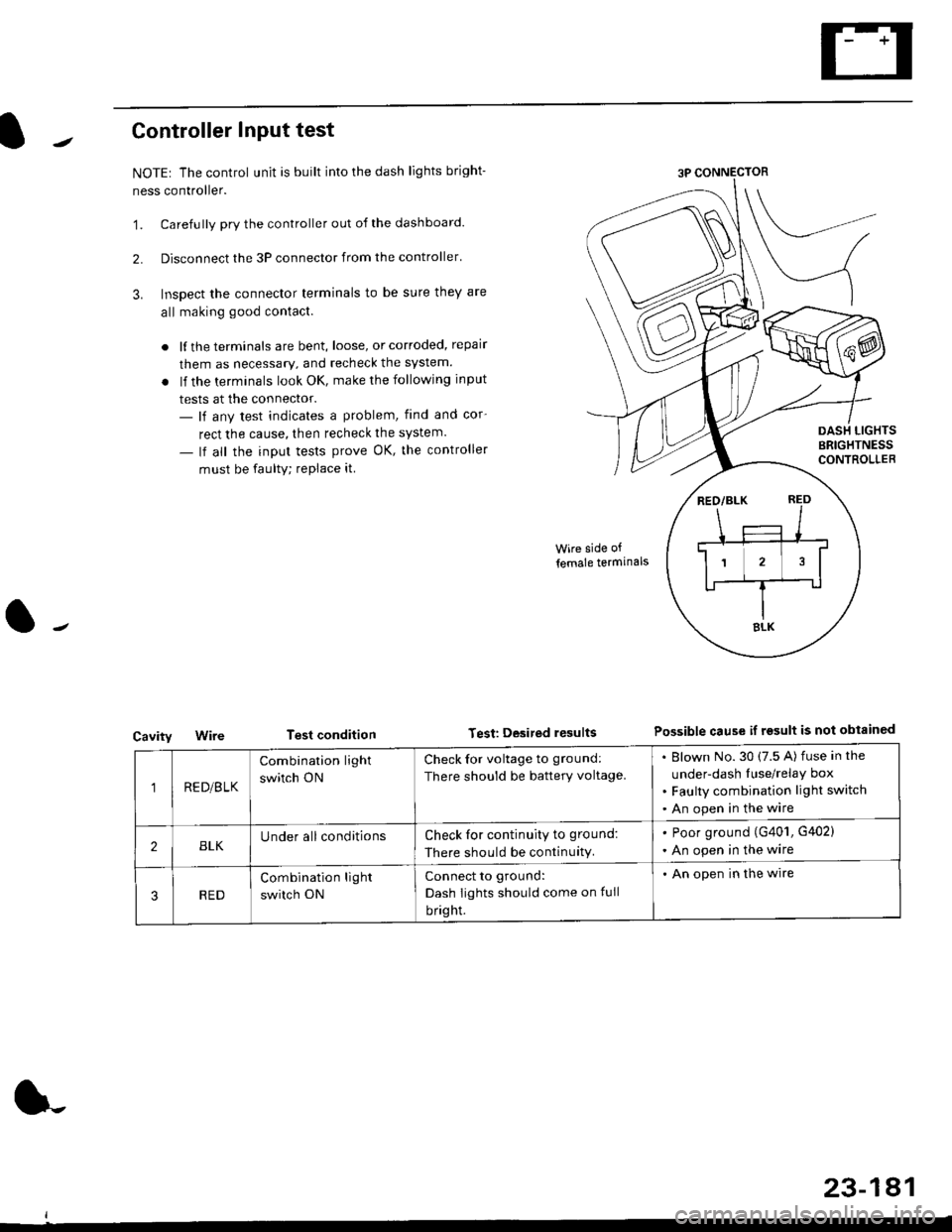
Controller Input test
NOTEr The control unit is built into the dash lights bright-
ness controller.
'1. Carefully pry the controller out of the dashboard.
2. Disconnect the 3P connector from the controller'
3. Inspect the connector terminals to be sure they are
all making good contact.
. lf the terminals are bent, loose, or corroded, repair
them as necessary, and recheck the system.
. lf the terminals look OK, make the following input
tests at the connector.- lf any test indicates a problem, find and cor-
rect the cause, then recheck the system.
- lf all the input tests prove OK, the controller
must be faulty; replace it
Cavity
Wire side of
lemale termlnals
Test condition Test Desited resultsPossible cause if rgsult is not obtainGd
1RE D/B LK
Combination light
switch ON
Check for voltage to ground:
There should be battery voltage.
Blown No.30 (7.5 A) fuse in the
under-dash Iuse/relay box
Faulty combination light switch
An open in the wire
2BLKUnder all conditionsCheck for continuity to ground:
There should be continuity.
. Poor ground (G401, G402)
. An open in the wire
RED
Combination light
switch ON
Connect to ground:
Dash Iights should come on full
bright.
. An open in the wire
23-181
Page 1659 of 2189
![HONDA CIVIC 1998 6.G Workshop Manual UNDER DASHFUSE/RELAY 80X
r*.i,,";l
I
I
I
I
I
I
IYEUFEDWHTiELU
Circuit Diagram (96 - 98 modelsl
A15A16
NoJ0 (7 sA)
v
IRED]BLK
RED
I
I
I
J
DASH LIGHTSBRIGHTNESSCONTROLLER
ANTENNALEAD
BRN/WHTBLK
G501
LE HONDA CIVIC 1998 6.G Workshop Manual UNDER DASHFUSE/RELAY 80X
r*.i,,";l
I
I
I
I
I
I
IYEUFEDWHTiELU
Circuit Diagram (96 - 98 modelsl
A15A16
NoJ0 (7 sA)
v
IRED]BLK
RED
I
I
I
J
DASH LIGHTSBRIGHTNESSCONTROLLER
ANTENNALEAD
BRN/WHTBLK
G501
LE](/img/13/6068/w960_6068-1658.png)
UNDER DASHFUSE/RELAY 80X
r*.i,,";l
I
I
I
I
I
I
IYEUFEDWHTiELU
Circuit Diagram ('96 - 98 modelsl
A15A16
NoJ0 (7 sA)
v
IRED]BLK
RED
I
I
I
J
DASH LIGHTSBRIGHTNESSCONTROLLER
ANTENNALEAD
BRN/WHTBLK
G501
LEFT FHONTDOOF SPEAKER
I RED,^/Er
ILI�l
RIGHT REARSPEAKER
I BLU/YEL
III�t
SPEAKER
q-
IGN TION SWITCHUNDER.HOOD FUSE/FELAY BOX
AUDIO UN T(STEREO RAOLO TUNER)
@
LEFTRIGHTTWEETER
GRY]BLK
23-189
Page 1660 of 2189
![HONDA CIVIC 1998 6.G Workshop Manual Stereo Sound System
UNDER-DASI.]FUSEi RELAY 8OX
l- -r,*;l
I
I
I
I
I
I
IYEUFED
(Sedan)--l
(Coupe/Horchbach)
Circuit Diagram (99 - 00 models)
No 30 (7.54)FUSE
V
IRED/BLK
I
I
I
vDASH LGHTSBHIGHTNESSCON HONDA CIVIC 1998 6.G Workshop Manual Stereo Sound System
UNDER-DASI.]FUSEi RELAY 8OX
l- -r,*;l
I
I
I
I
I
I
IYEUFED
(Sedan)--l
(Coupe/Horchbach)
Circuit Diagram (99 - 00 models)
No 30 (7.54)FUSE
V
IRED/BLK
I
I
I
vDASH LGHTSBHIGHTNESSCON](/img/13/6068/w960_6068-1659.png)
Stereo Sound System
UNDER-DASI.]FUSEi RELAY 8OX
l- '-r,*;l
I
I
I
I
I
I
IYEUFED
(Sedan)--l
(Coupe/Horchbach)
Circuit Diagram ('99 - 00 models)
No 30 (7.54)FUSE
V
IRED/BLK
I
I
I
vDASH LGHTSBHIGHTNESSCONTROLLER
F;*";
,,,[.J:,a*[rrl
BLK
G501
/ _- | neolcn;diFnoNi | |DooR SPEAKEF | |
HlGHTTWEETER
UNDER.HOOD FUSE/RELAY BOX
RIGHT REAFSPEAKEBLEFT REARSPEAKEF
LEFTTWEETER
23-190
Page 1666 of 2189
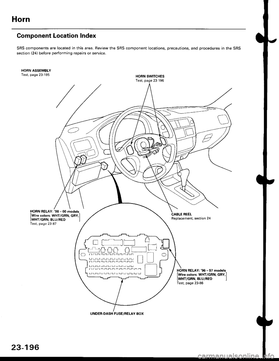
Horn
Component Location Index
SRS components are located in this area. Review the SRS component locations, precautions, and procedures in the SRS
section (24) before performing repairs or service.
CABLE REELReplacement, section 24
(:-, ,,/ t.\
(6\'
\K2
HORN RELAY: '98 - 00 models-
lWire colorsr WHT/GRN, cBY,lIWHT/GRN, BLU/RED ]Test, page 23 87
HORN RELAY: '96 -97 models-lwire colors: WHT/GRN. GBY,I
IWHT/GRN, BLU/RED ITest, page 23-86
UNDER-DASH FUSE/RELAY BOX
23-196
Page 1670 of 2189
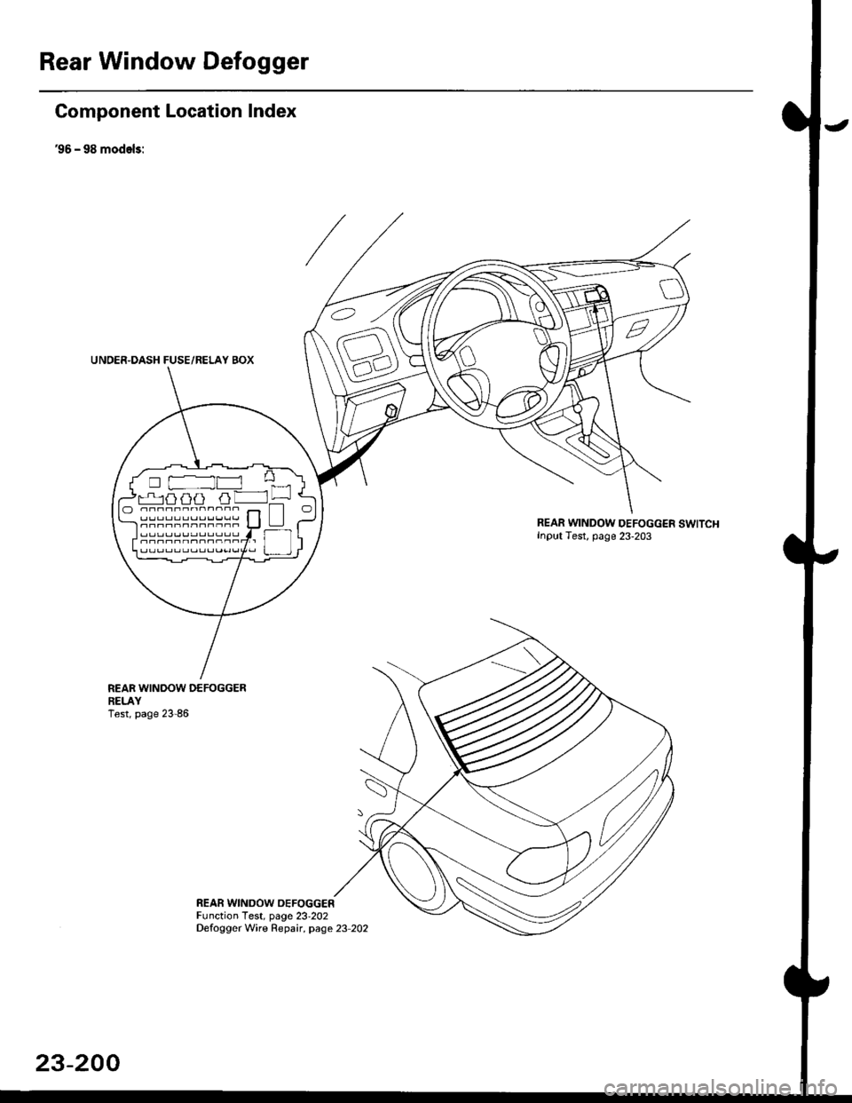
Rear Window Defogger
Gomponent Location Index
36 - 98 modols:
UNDER.DASH FUSE/RELAY BOX
REAR WINDOW DEFOGGER SWITCHInput Test, page 23-203
REAR WINOOW DEFOGGERRELAYTest, page 23-86
REAR WINOOW OEFOGGERFunction Test, page 23'202Defogger Wire Repair. page 23 202
23-200
Page 1675 of 2189
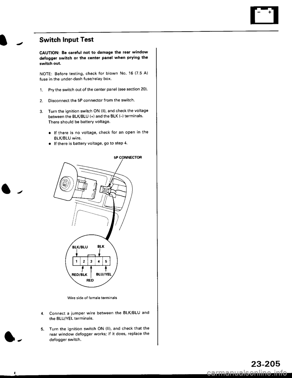
Switch Input Test
CAUTION: Be careful not to damagc the rear window
defogger switch or the center panel when prying the
switch out.
NOTE: Before testing, check for blown No. 16 (7.5 A)
fuse in the under-dash fuse/relay box,
1. Pry the switch out of the center panel (see section 20).
2. Disconnect the 5P connector from the switch.
3. Turn the jgnition switch ON (ll), and check the voltage
between the BLVBLU {+) and the BLK (-)terminals.
There should be battery voltage
. lf there is no voltage, check for an open in the
BLVBLU wire.
. lfthere is baftery voltage, go to step 4.
Wire side of famale terminals
connect a jumper wire between the BLK/BLU and
the BLU/YEL terminals.
Turn the ignition switch ON (ll), and check that the
rear window defogger works; if it does. replace the
defogger switch.
4.
RED
l-
23-205
Page 1677 of 2189
![HONDA CIVIC 1998 6.G Workshop Manual Circuit Diagram (Without Defogger)
UNDER.HOOD FUSE]FELAY BOX
eo;T f-*---;,;r j-_l 6\
OF+-*.v-f r--;. -"j-a,_cy
GN TIONSWITCH
UNDER DASHFUSEIRELAYBOX
BLK]YEL
) I dRGHT LEFTd I dFlGHrf- -- ---\,
HONDA CIVIC 1998 6.G Workshop Manual Circuit Diagram (Without Defogger)
UNDER.HOOD FUSE]FELAY BOX
eo;T f-*---;,;r j-_l 6\
OF+-*.v-f r--;. -"j-a,_cy
GN TIONSWITCH
UNDER DASHFUSEIRELAYBOX
BLK]YEL
) I dRGHT LEFTd I dFlGHrf- -- ---\,](/img/13/6068/w960_6068-1676.png)
Circuit Diagram (Without Defogger)
UNDER.HOOD FUSE]FELAY BOX
eo;T f-*---;',;r j-_l 6\
OF+-*'.v-f r'--;.' -"j-'a,_cy'
GN TIONSWITCH
UNDER DASHFUSEIRELAYBOX
BLK]YEL
) I dRGHT LEFTd I dFlGHr'f- -- ---\,
TT
I
I.t.olo
G551
23-207
(}-
Page 1679 of 2189
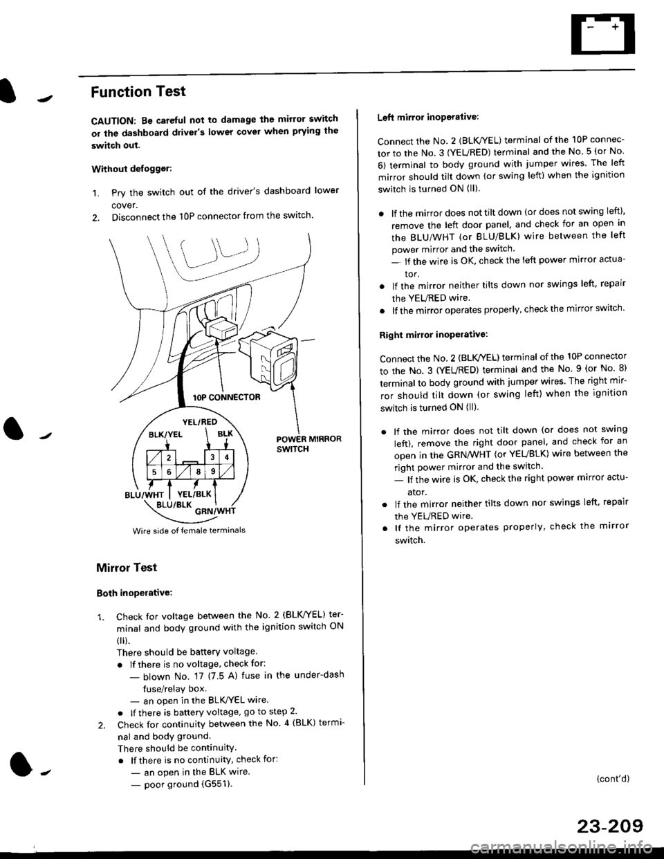
Function Test
CAUTION: Be careful not to damage the mirror switch
or the dashboard drivel's lower covel when prying the
swhch out.
Withoui defogger:
1. Pry the switch out of the driver's dashboard lower
cover.
2. Disconnect the 10P connector from the switch.
lOP CONNECTOR
BLU/WHT
YEL/RED
BLK/YELBLK
4
568
YEL/BLK
POWER MIRRORswtTcH
\:/"*jgil*-(
Wire side of female termanals
Mirror Test
Both inoperative:
1. check for voltage between the No. 2 (BLVYEL) ter
minal and body ground with the ignition switch ON
0 r).
There should be batterY voltage
. If there is no voltage, check for:
- blown No. 17 (7 5 A) fuse in the under-dash
tuse/relay box- an open in the BLK'/YEL wire.
o lf there is battery voltage, go to step 2.
2. Check for continuity between the No 4 (BLK) termi-
nal and body ground.
There should be continuity.
. lf there is no continuity, check for:
- an open in the BLK wire.
- poor ground (G551).
Left mirror inoporalive:
connect the No. 2 {BLK/YEL) terminal of the 10P connec-
tor to the No. 3 (YEURED) terminal and the No 5 (or No
6) terminal to body ground with jumper wires The left
mirror should tilt down (or swing left) when the ignition
switch is turned ON (ll)
. lf the mirror does not tilt down (or does not swing left),
remove the left door panel. and check for an open in
the BLU/WHT (or BLU/BLK) wire between the left
power mirror and the switch
- lf the wire is OK. check the left power mirror actua-
tor.
lf the mirror neither tilts down nor swings left. repair
the YEURED wire.
lf the mirror operates properly, check the mirror switch'
Right mirror inoperative:
Connect the No. 2 (BLK /EL) terminal of the 10P connector
to the No. 3 (YEURED) terminal and the No. 9 (or No 8)
terminal to body ground with jumper wires The right mir-
ror should tilt down (or swing left) when the ignition
switch is turned ON (ll).
. lf the mirror does not tilt down (or does not swlng
left), remove the right door panel. and check for an
open in the GRN/WHT (or YEUBLK) wire between the
right power mirror and the switch.
- lf the wire is OK, check the right power marror actu-
ator.
. lf the mirror neither tilts down nor swings left. repair
the YEURED wire
. lf the mirror operates properly, check the mirror
switch.
(cont'd)
23-209
Page 1680 of 2189
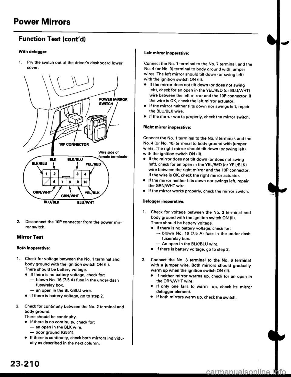
Power Mirrors
Funstion Test (cont'dl
With dcfoggcr:
1. Pry the switch out ot the driver's dashboard lowercover.
2. Disconnect the 10P coonector from the oower mir-ror switch.
Mirror Test
Bolh inoparrtiv.:
1. Check for voltage between the No. 1 terminal andbody ground with the ignition switch ON flt).There should be battery voltage.. lf there is no battery voltage, check to.:- blown No. 16 (7.5 A) fuse in the under-dash
tuse/relay box.- an open in the BLVBLU wrre.
! lf thero is banery voltage, go to step 2.
2. Check for continuity b€tween the No. 2 terminal andbody ground.
There should be continuitv.. ll there is no continuity, check tor:- an open in the BLK wire.- poor ground (G5511.
. lJthere is continuity. check both mirrors individu-ally 8s described in the next column,
23-210
Laft mirror inopcrativ!:
Connect the No. 1 terminal to the No. 7 terminal. and theNo. 4 (or Nb.9) terminalto body ground with jumper
wires. The left mirror should tilt down (or swing left)with the ignition switch ON (ll).
. lf the mirror does not tilt down (o. does not swinglett), check for an open in the YEURED (or BLUMHT)wire between the left mirror and the 10p connector. lfthe wire is OK, check the left mirror actuator.a lf the mirror neither tilts down nor swings left, repairthe BLU/BLK wire.
t lf the mirror works properly, check the mirror switch.
Right mi.ror inopcrativc:
Connect the No. 1 terminal to the No. 8 terminal, and theNo.4 (or No. 10) terminalto body ground with l'umperwi.es. The right mirror should tilt down (or swing lett)with the ignition switch ON (ll).
. lf the mirror does not tilt down {or does not swingleft), check for an open in the YEURED {or YEUBLK)
wire between the right mirror and the l0P connector.lf the wire is OK, check the right mirror actuator,. lf the mirror neither tilts down nor swings left, repairthe GRN/WHT wire.o lf the mirror works properly. check the mirro. switch,
Dafoggcr inoperEtivo:
1. Check for voltage between the No. 3 terminal andbody ground with the ignition switch ON (||).
There should be battery voltage.a lf there is no battery voltage, check for;- blown No. 16 (7.5 A) luse in the under-dash
fuse/rel8y box,- An open in the BLK,iBLU wire.. It there is battery voltage, go to step 2.
2. Connsct the No. 3 tsrminal to the No. 6 terminalwith a iumpsr wire. Both mirrors should gradually
warm up when the ignition switch ON flt).a lf neither mirror warms up, check for an open inthe ORN/WHT wire.. It only on€ lails to warm up, check its mirrordsfogger elem6nt.. lf both mirrors warm up, check ths switch.
Page 1690 of 2189
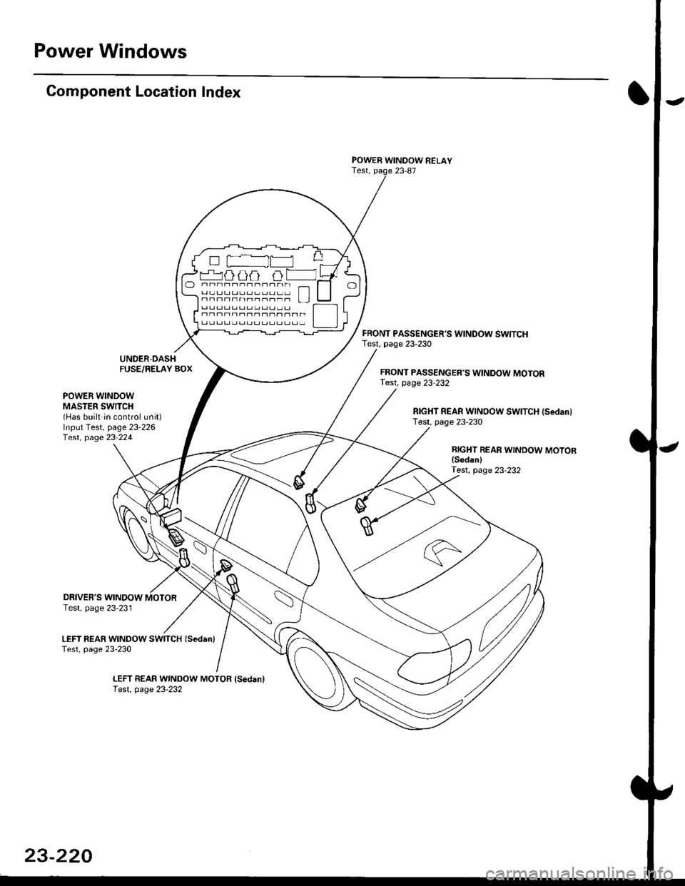
Power Windows
Gomponent Location Index
UNDER-DASHFUSE/RELAY BOX
POWER WINDOW RELAYTest, paqe 23 87
FRONT PASSENGER'S WINDOW SWITCHTest. page 23-230
FRONT PASSENGER'S WINDOW MOTORTest, page 23-232
POWER WINDOWMASTER SWITCH(Has built in control unit)Input Test, page 23-226f e$, page 23 224
RIGHT REAR WINOOW SWITCH {SedanlTest, page 23-230
BIGHT REAR WINDOW MOTORlSedanlTest, page 23-232
DRIVER'S WINOOW MOTORTest, page 23-231
LEFT REAR WINDOW SWITCH (Sedan)
Test, page 23-230
LEFT BEAR WINDOW MOTOR {Sedanlf e$, page 23-232
O -rr----r---- _ fl]l O-.---,---;-; n-n--n-nn--r- ! l