connector plug HONDA CIVIC 1998 6.G User Guide
[x] Cancel search | Manufacturer: HONDA, Model Year: 1998, Model line: CIVIC, Model: HONDA CIVIC 1998 6.GPages: 2189, PDF Size: 69.39 MB
Page 489 of 2189
ldle Control System
ldle Speed Setting
Inspection/Adiustmenl
'96, '97 Dl6Y5. '96 - 00 Dl5Y8 sngine with M/T
NOTE:
. Before setting the idle speed, check the following
items:- The MIL has not been reported on.- lgnition timing- Spark plugs- Air cleaner- PCV system
o (Canada) Pull the parking brake lever up. Start the
engine, then check that the headlights are off.
1. Start the engine. Hold the engine at 3.000 rpm withno load (taansmission in neutral) until the radiatorfan comes on, then let it idle.
2. Connect a tachometer.
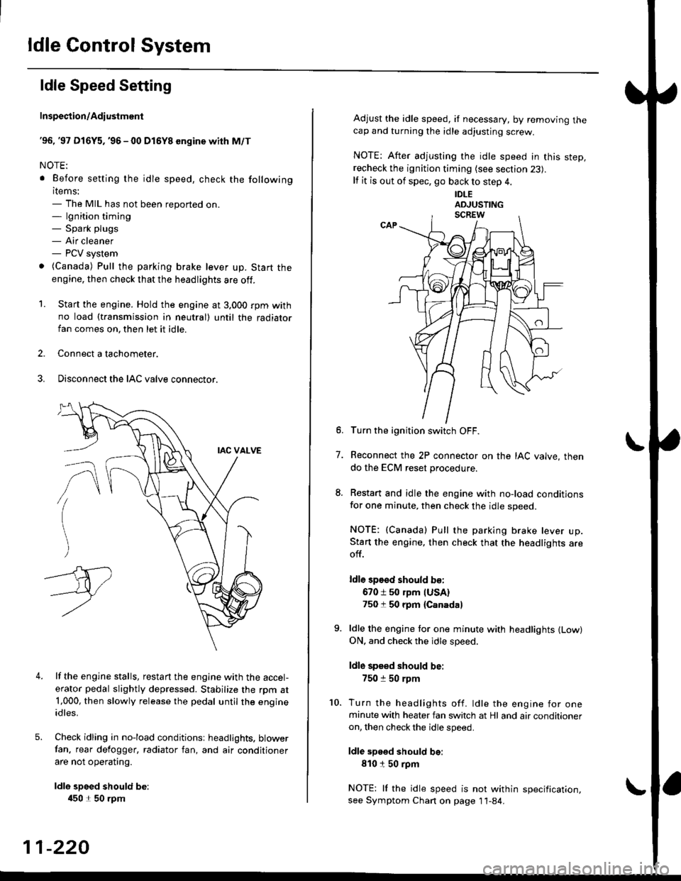
3. Disconnect the IAC valve connector.
4.lf the engine stalls, restart the engine with the accel-
erator pedal slightly depressed. Stabilize the rpm at1,000, then slowly release the pedal until the engineidles.
Check idling in no-load conditionsr headlights. blowerfan. rear defogger, radiator fan, and air conditioner
are not operating.
ldle spsed should be:
450 1 50 rpm
11-220
Adjust the idle speed, if necessary, by removing thecap and turning the idle adjusting screw.
NOTE; After adjusting the idle speed in this step,recheck the ignition timing (see section 23).
lf it is out of spec, go back to step 4.
IDLE
6. Turn the ignition switch OFF.
7. Reconnect the 2P connector on the IAC valve, then
do the ECM reset procedure.
8. Restart and idle the engine with no-load conditionsfor one minute, then check the idle speed.
NOTE: (Canada) Pull the parking brake lever up.Start the engine, then check that the headlights areoff.
ldle sp€sd should b€:
670 i 50 rpm IUSA)750 t 50 rpm {Canada}
9. ldle the engine tor one minute with headlights {Low)ON. and check the idle speed.
ldle speed should be:
750 :r 50 rpm
10. Turn the headlights off. ldle the engine for oneminute with heater fan switch at Hl and air conditioneron, then check the idle speed.
ldle speed should be:
810150 rpm
NOTE: lf the idle speed is not within specification,see Symptom Chan on page 11-84.
Page 490 of 2189
t
t
I
'96.'97 D16Y5 engine with CVT,'96 - 00 D16Y8 ongins
with A/T and'96 - 00 Dl6Y7 €ngine
Adiust the idle speed using a Honda PGM Tester if pos-
sible. lf not, use the following procedure:
NOTEI
. Leave the IAC valve connected
. Betore setting the idle speed. check the following
items:- The MIL has not been reported on'
- lgnition timing
- Spark Plugs- Air cleaner- PCV system
1. Connect a tachometer.
2. Start the engine. Hold the engine at 3,000 rpm wirh
no load (in Park or neutral) until the radiator fan
comes on, then let it idle.
3. Check the idle speed with no-load conditions: head-
iights, blower fan, rear defogger, radiator fan, and
air conditioner are not operatlng
ldl€ spoed should be:
USA:
D16Y5 engine with CVT, D16Y7 engine with A/T'
Dl6YB engine with A/T:
700 :r 50 rpm (in E or El Positionl
D16Y7 engine with M/T:
670 i 50 rpm
Canada:
Dl6Y8 sngin€, Dl6Y7 engins:
M/T750 t 50 rpm
NT750 1 50 rpm (in E or El Position)
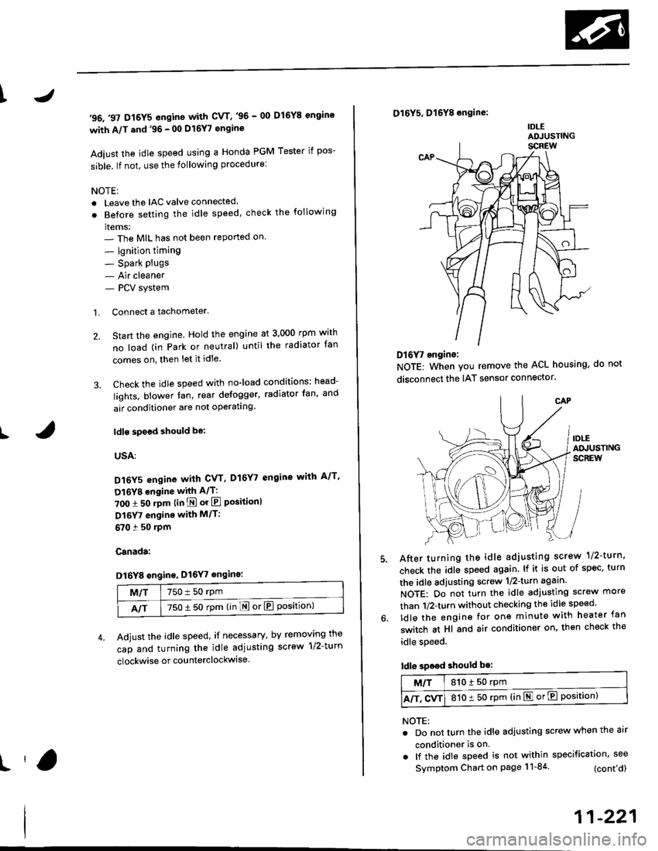
Adjust the idle speed, if necessary, by removing the
cap and turning the idle adiusting screw 1/2-turn
clockwise or counterclockwise
D16Y5, D16Y8 engine:
IDLEADJUSTING
Dl6f, ongine:
NOTE: When you remove the ACL housing, do not
disconnect the IAT sensor connector
After turning the idle adjusting scrow 1/2-turn'
check the idle speed again. lf it is out of spec, turn
the idle adjusting screw 1/2-turn agaan'
NOTE: Do not turn the idle adjusting screw more
than 1/2-turn without checking the idle speed'
ldle the engine for one minute with heater fan
switch at Hl and air conditioner on, then check the
idle speed.
ldle speed should be:
M/T810150 rpm
A/T. CvT810 t 50 rpm (in El or E Position)
NOTE:
. Do not turn the idle adjusting screw when the air
conditioner is on.
. lf the idle speed is not within specification. see
Symptom Chart on page 11-84 (cont'd)
11-221
Page 491 of 2189
ldle Control System
ldle Speed Setting (cont'dl
Inspeqtion/Adiustment
38 D16Y5 engine whh M/T,'99 - 00 81642 engine
NOTE: Before setting the idle speed, check the follow-ing items;- The MIL has not been reported on.- lgnition timing- Spark plugs- Air cleaner- PCV system
'1. Start the engine. Hold the engine at 3,000 rpm withno load (transmission in neutral) until the radiatorfan comes on, then let it idle.
Connect a tachometer.
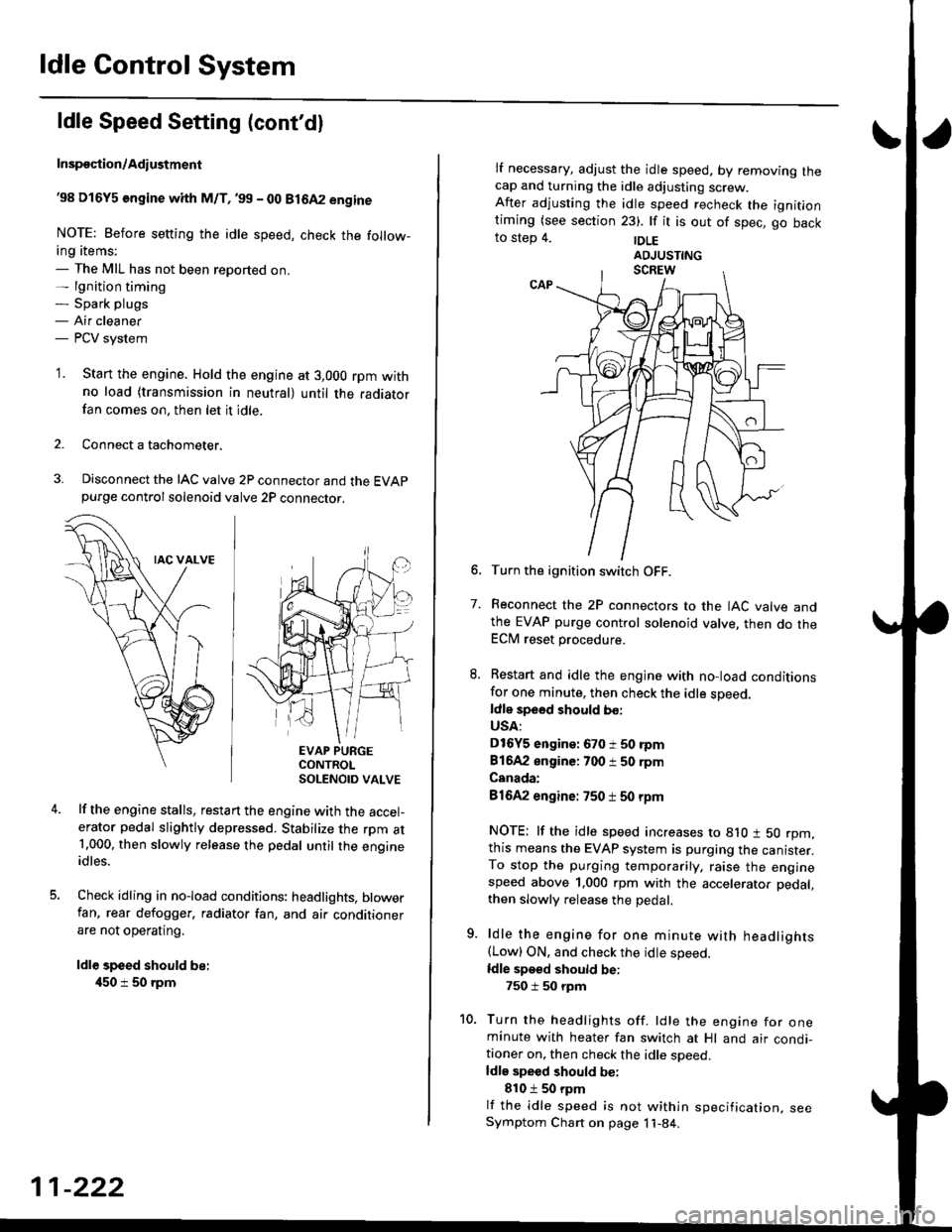
Disconnect the IAC valve 2P connector and the EVAPpurge controlsolenoid valve 2P connector.
EVAP PURGECONTROLSOLENOID VALVE
lf the engine stalls, restart the engine with the accel-erator pedal slightly depressed. Stabilize the rpm at1.000, then slowly release the pedal until the engineidles.
Check idling in no-load conditions: headlights, blowerfan, rear defogger, radiator fan, and air conditionerare not operating.
ldl€ speed should be:
450 i 50 rpm
11-222
lf necessary, adjust the idle speed, by removrng lnecap and turning the idle adjusting screw.After adjusting the idle speed recheck the ignitlontiming (see section 23). lf it is out of spec, go backto step 4. |DLE
6. Turn the ignition switch OFF.
7. Reconnect the 2P connectors to the IAC valve andthe EVAP purge control solenoid valve, then do theECM reset procedure.
8. Restart and idle the engine with no-load conditionsfor one minute, then check the idle sDeed.ldle speed should bo:
USA:
D16Y5 engine: 670 i 50 rpm
81642 engine: 700 i 50 rpm
Canada:
81642 engine: 750 t 50 rpm
NOTE: lf the idle speed increases to 8lO t 50 rpm,this means the EVAP system is purging the canister.To stop the purging temporarily, raise the enginespeed above 1,000 rpm with the accelerator pedal,
then slowly release the pedal.
9. ldle the engine for one minute with headlights(Low) ON. and check the idle speed.
ldle speed should be:
750 i 50 rpm
10. Turn the headlights off. ldle the engine for oneminute with heater fan switch at Hl and air condi-tioner on, then check the idle soeed.ldls speed should be:
810 t 50 rpm
lf the idle speed is not within specification, seeSymptom Chart on page 11-84.
Page 492 of 2189
\
I
'98 - 0O D16Y5 ongine with CvT
Adjust the idle speed using a Honda PGM Tester if pos-
sible. lf not, use the following procedure:
NOTE:
. Leave the IAC valve connected.
. Before s€tting the idle speed, check the following
rtems:- The MIL has not been reported on.
- lgnition timing
- Spark Plugs- Air clean€r
- PCV svstem
'1. Connect a tachometer.
2. Stan the engine. Hold the engine at 3,000 rpm w'th
no load (transmission in E or E] position) until the
radiator Jan comes on, then let it idle.
3. Check the idle speed under no-load conditions:
head lights, blower fan, rear defogger, radiator fan,
and air conditioner are not operatlng.
ldlo spaod ehould bo: 700 t 50 rpm
. lf the idle speed is within the specification, the
procedure is comPlete.
. lf the idle sDeed is out of specitication, 9o to step 4'
4. tf the idle speed is 810 1 50 rpm, this means the
EVAP system is purging the canister. To stop the
purging temporarily, raise the engine speed above
l,OO0 rgm with the accelsrator pedal. Slowly release
the pedal. and rscheck the idl€ speed.
. tf the idle speed is within the specificstion, the
Drocedure is comPlete.
. lf the idle sp€ed is out of spocification, go to step 5.
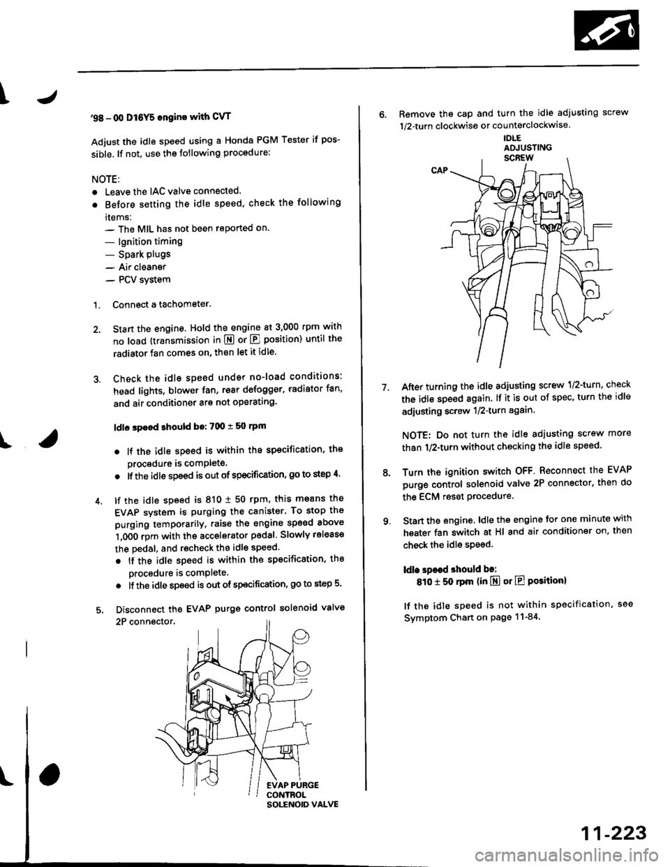
5. Disconnect th€ EVAP purgs control solenoid valve
2P connector.
EVAP PURGECONTROL
6. Remove the cap and turn the idle adiusting screw
1/2-turn clockwise or counterclockwlse
IDLE
7.After turning the idle adjusting screw 1/2-turn, check
the idl€ speed again. lf it is out of spec, turn the idle
adjusting screw 1/2-turn again.
NOTE: Do not turn the idle adjusting screw more
than 1/2-turn without checking the idle speed.
Turn the ignition switch OFF. Reconnect the EVAP
purge control solenoid valve 2P connector' then do
the ECM reset Procedure.
Start the engine. ldle the engine for one minute with
heater fan switch at Hl and air conditioner on, then
check the idle speed.
ldle spaed should be:
810 t 50 rpm (in El or E Posiiion)
lf the idle speed is not within specification, see
Svmptom Chart on Page 11-84.
9.
SOLENOID VALVE
11-223
Page 583 of 2189
MaintenanceBack-up Light Switch
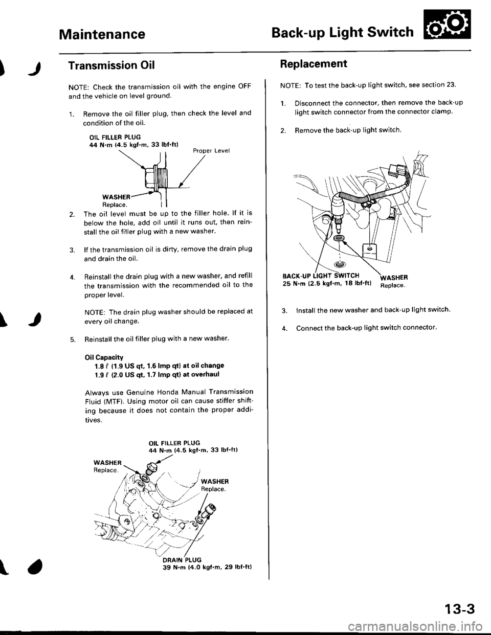
Transmission Oil
NOTE: Check the transmission oil with the engine OFF
and the vehicle on level ground.
1. Remove the oil filler plug, then check the level and
condition of the oil.
OIL FILLER PLUG/14 N.m (4.5 kgl.m,33 lbl.ft)Proper Level
4.
WASHERReplace.
The oil level must be up to the filler hole. lf it is
below the hole, add oil until it runs out. then rein-
stall the oil filler plug with a new washer.
lf the transmission oil is dirty, remove the drain plug
and drain the oil.
Reinstall the drain plug with a new washer, and refill
the transmission with the recommended oil to the
proper lever.
NOTE: The drain plug washer should be replaced at
every oil change.
Reinstall the oil filler plug with a new washer.
OilCapacity
1.8 f (1.9 US qt. 1.6 lmp qtl at oil change
1.9 { (2.0 US $, 1.7 lmp qt) at overhaul
Always use Genuine Honda Manual Transmission
Fluid {MTF). Using motor oil can cause stiffer shift-
ing because it does not contain the proper addi-
t|ves.
\
\
Replacement
NOTE: To test the back-up light switch, see section 23
1. Disconnect the connector, then remove the back-up
light swirch connector from the connector clamp.
2. Remove the back-up light switch.
25 N.m (2.5 kgf'm, 18lbf'ltl
Install the new washer and back-up light switch
Connect the back-up light switch connector.
ASHER
13-3
Page 627 of 2189
MaintenanceBack-up Light Switch
\
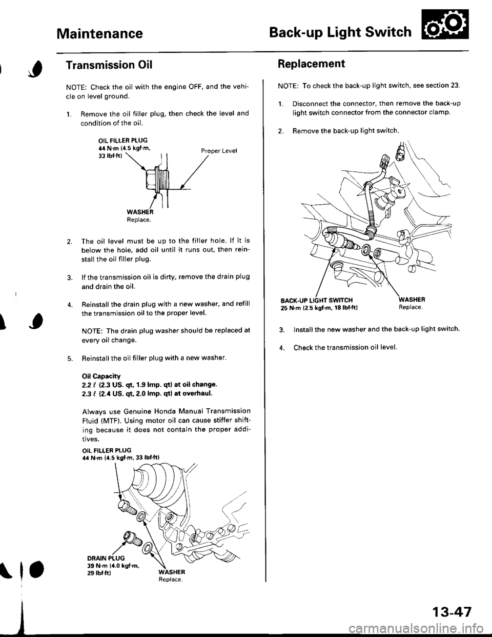
Transmission Oil
NOTE: Check the oil with the engine OFF. and the vehi-
cle on level ground.
1. Remove the oil filler plug, then check the level and
condition of the oil.
OIL FILLER PLUGia4 N.m {{.5 kgf'm,Proper Level33 tbtfrl
The oil level must be up to the filler hole. lf it is
below the hole, add oil until it runs out, then rein-
stall the oil filler plug.
lf the transmission oil is dirty, remove the drain plug
and drain the oil.
Reinstall the drain plug with a new washer. and refill
the transmission oil to the proper level.
NOTE: The drain plug washer should be replaced at
every oil change.
Reinstallthe oilfiller plug with a new washer.
Oil Capacity
2.2 f {2.3 US. qt, 1.9 lmp. qtl at oil change.
2.3 f {2./f US. qt. 2.0 lmp. qt} at overhaul.
Always use Genuine Honda Manual Transmission
Fluid (MTF). Using motor oil can cause stiffer shift-
ing because it does not contain the proper addi-
tives.
OIL FILLER PLUGila N.m {4.5 kgf.m, 33 lbt'ftl
Replace.
\1,
Replacement
NOTE: To check the back-up light switch, see section 23.
1. Disconnect the connector, then remove the back-up
light switch connector from the connector clamp.
2. Remove the back-up lighr switch.
AACK.UP25 N.m 12.5 kgf.m, 18 lbf'tt)Replace.
lnstall the new washer and the back-up light switch.
Check the transmission oil level.4.
Page 628 of 2189
Transmission Assembly
l
,
{
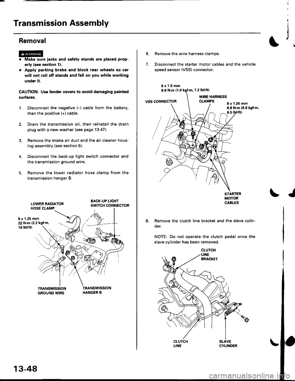
Removal
@Make sure iacks and safoty stands are placad plop-
erly (3ee section l).
Apply parking braks and block rear wheels so car
will not roll off stands and fall on you while working
under il.
CAUTION: Us6 fonder cove6 to avoid damaging painted
sudaces.
Disconnect the negative (-) cable from the battery,
then the positive (+l cable.
Drain the transmission oil. then reinstall the drain
plug with a new washer (see page 13-47).
Remove the intake air duct and the air cleaner hous-
ing assembly (see s€ction 5).
Disconnect the back-up light switch connector and
the transmission ground wire.
Remove the lower radiator hose clamp from the
transmission hanger B.
L
8 x 1 .25 mm22Nm12.2kgl'm�,
LOWER RADIATORHOSE CLAMP
16 rbtft)
13-48
7.
Bemove the wire harness clamps.
Disconnect the starter motor cables and the vehicle
speed sensor (VSS) connector.
8 x 1.25 mm8.8 N.m (0.9 kgf.m,6.5 tbtftl
STARTERMOTORCABLES
8. Remove the clutch line bracket and the slav6 cylin-
oer.
NOTE: Do not operate the clutch pedal once the
slave cylinder has been removed.
\J
Page 801 of 2189
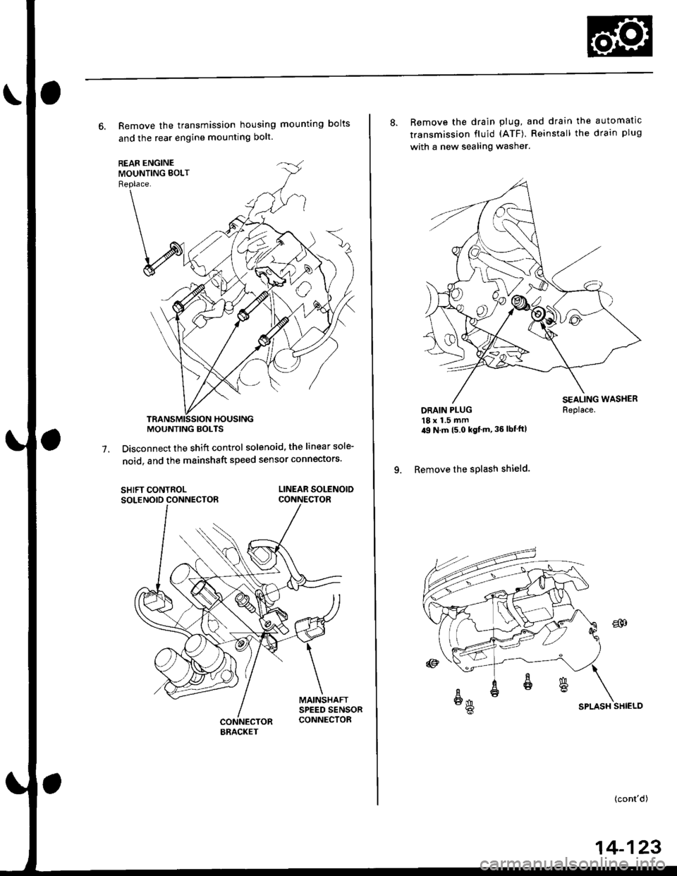
6. Remove the transmission housing mounting bolts
and the rear engine mounting bolt.
Disconnect the shift control solenoid, the linear sole-
noid, and the mainshaft speed sensor connectors'7.
SHIFT CONTROLSOLENOID CONNECTORLINEAR SOLENOIDCONNECTOR
MOUNTING BOLTS
BRACKET
8. Remove the drain plug, and drain the automatic
transmission fluid (ATF). Reinstall the drain plug
with a new sealing washer.
DRAIN PLUG18 x 1.5 mm'9 N m t5 o kgf'm' 36 lbf'ft|
9. Remove the splash shield.
Replace.
SPLASH SHIELD
{cont'd)
14-123
Page 979 of 2189
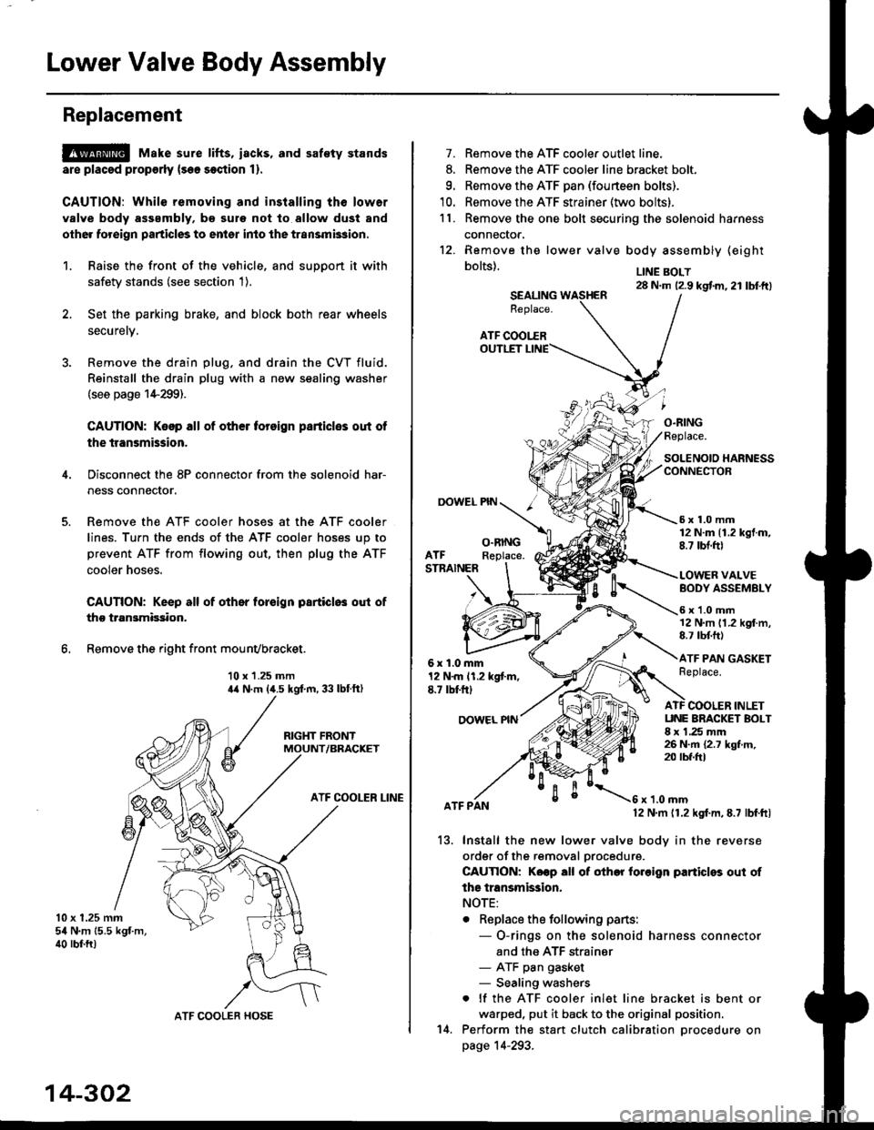
Lower Valve Body Assembly
Replacement
@ Make sure lifts, iacks, and saf€ty stands
are placsd prop€rly {sea section 1).
CAUTION: While removing and installing th6 lower
valve body asssmbly, b€ sule not to allow dust and
other for€ign particles to entsr inio the transmksion.
1. Raise the front of the vehicle, and support it with
safetv stands (see section 1).
2. Set the parking brake, and block both rear wheels
securetv.
4.
6.
Remove the drain plug, and drain the CVT fluid.
Reinstall the drain plug with a new sealing washer(see page 1+299).
CAUTION: Keop all of other toreign parliclos out of
the transmission.
Disconnect the 8P connector from the solenoid har-
ness connector.
Remove the ATF cooler hoses at the ATF cooler
lines. Turn the ends of the ATF cooler hoses up to
prevent ATF from flowing out, then plug the ATF
cooler noses.
CAUTION: Keep all of other foroign particlo3 out of
tho transmission.
Remove the right front mounvbracket.
10 x 1.25 mmila N.m (,1.5 kgf.m, 33 lbtft)
RIGHT FRONTMOUNT/BRACKET
ATF COOLER LINE
10 x 1.25 mmsil N.m 15.5 kgf.m,40 rbr.ft)
ATF COOLER HOSE
14-302
14.
7. Remove the ATF cooler outlet line.
8. Remove the ATF cooler line bracket bolt.
9. Remove the ATF pan (fourteen bolts).
10. Remove the ATF strainer (two bolts).
1 l. Remove the one bolt securing the solenoid harness
connector,
12. Remove the
bolts).
lower valve body assembly (eight
LINE BOLT28 N.m (2.9 kgtm,21 lbtft)SEALINGReplace.
ATF COOI.-EROUTLET
OOWEL PIN
O.RINGFeplace.
SOLENOIO HARNESSCONNECTOR
5x1.0mm12 N.m 11.2 kgt.m,8.7 tbt.ftlO.RINGReplace.ATFSTNAINER
6x1.0mm12 N.m 11.2 kgt m,E.7 tbt'ft)
OOWEL NN
BODY ASSEMBLY
6x1.0mm12 N.m 11.2 kgf.m,8.7 rbf.ft)
ATF PAN GASKETReplace.
VALVE
ATF COOLER INLETUNE BRACKET BOLT8 x 1,25 mm26 N.m {2.7 kgf.m,20 tbf.frl
13.
ATF PANx 1.0 mm12 N.m 11.2 kgf.m, E.7 lbf.ftl
Install the new lower valve bodv in the reverse
ordgr of the removal orocedure.
CAUTION: Koep all ot other fo.oign particles out of
ths transmission.
NOTE:
. Replace the following parts:
- O-rings on the solenoid harness connector
and the ATF strainer- ATF pan gasket- Sealing washers
. lf the ATF cooler inlet line bracket is bent or
warped, put it back to the original position.
Perform the start clutch calibration orocedure on
page 14-293.
Page 982 of 2189
I
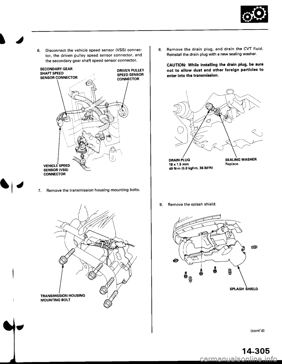
6. Disconnect the vehicle speed sensor (VSS) connec-
tor, the driven pulley speed sensor connector, and
the secondary gear shaft speed sensor connector.
SECONDARY GEARSHAFT SPEEDORIVEN PULLEY
SPEED SENSORCONNECTORSENSOR
7. Remove the transmission housing mounting bolts.
14-305
8. Remove the drain plug, and drain th€ CVT fluid
Reinstall the drain plug with a new sealing washer.
CAUTION: While installing the drain plug' bo 3ur.
nol io allow du3l 8nd other toreign particles to
enter into th€ trsnsmi$ion.
DRAIN PLUG18 x 1.5 rnm(, N.m (5.0 kgfm, 36 lbf'ft|
9. Remove the splash shield.
SEALING WASHERReplaco.