data link HONDA CIVIC 1998 6.G User Guide
[x] Cancel search | Manufacturer: HONDA, Model Year: 1998, Model line: CIVIC, Model: HONDA CIVIC 1998 6.GPages: 2189, PDF Size: 69.39 MB
Page 738 of 2189
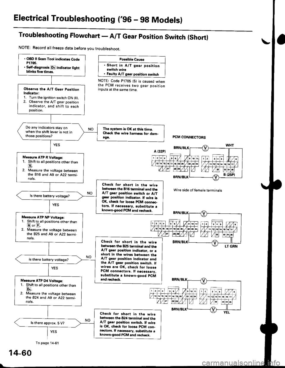
Electrical Troubleshooting ('96 - 9g Models)
Troubleshooting Flowchart - A/T Gear position Switch (Shortl
NOTE: Record allfreeze data before you troubleshoot.
Poiriblo Caus6
. Short in A/T go.. positionawhch wira. Fauhy A/T goa. position swhch
NOTE: Code P1705 (5)the PCM receives twoinputs at the same time.
is caused whengear position
' OBD ll Scln Toot indic.tes Cod6P1705.. Sofidi.gno3b E indicato] tighrblinksfivatim...
Observo th. A/T Go.r po3ition
Indicator:1. Turn the ignition switch ON l).2. Observe the A"/T gear positionindicator, and shitt to eachposttron,
Do any indicatoG stay onwhen the shift lever is not inthose positions?
Tho sy3tem b OK.t this timo.Check th6 wilc harnari for dam-rga.
M.r.ur. ATP R Vohlge:1. Shift to all positions otherthanE.2. Nileasure the voltage betweenthe 816 and Ag or A22 tormi-nats,
Check for short in tha wirobstwacn the 816 tcrminal and th6A/T go.r porition rwitch or A/Tg..r position indicltor. It wira i3OK, ch.ck for loo!€ FCfit connoc-to13. lf nacetaary, subrtitute aknown€ood Pcllt and roa|rsck.
ls there battery voltage?
Meesur. ATP NP Vohage:1. Shift to allpositions oth€r thanEorE.2. Moasure the voltage betweenthe 825 and A9 or A22 terminats.Check for short in the wireb.tw..n th6 B:I5 torminrt and th.A/T gclr poahion indicator. o. .short in tha wirrs between th.A/T gclr position indicator rndthe A/T gerr poiition switch. lfwir.3 r.o OK, chack tor loosoPCM conn.ctorr. It n.cosarry.sub.tituto a known-good pCM.nd r.chock.M.Gur. ATP D4 Voltago:1. Shift to allpositions otherthanlD.l.2. Measure the voltage betw€enrhe 824 and Ag or A22 termi-nals.
Check tor 3hort in tho wirobc{wocn the 824 terminrl and thoA/T ge.r poiition switch. lI wileia OK, chock tor loo3o plCM con-ncctoaa. It nacossarv, sublthute aknown-good PCM and rech€ck.
ls there approx. 5 V?
PCM CONNECTORS
Wire side of female terminals
YES
To page 14-6':
14-60
Page 740 of 2189
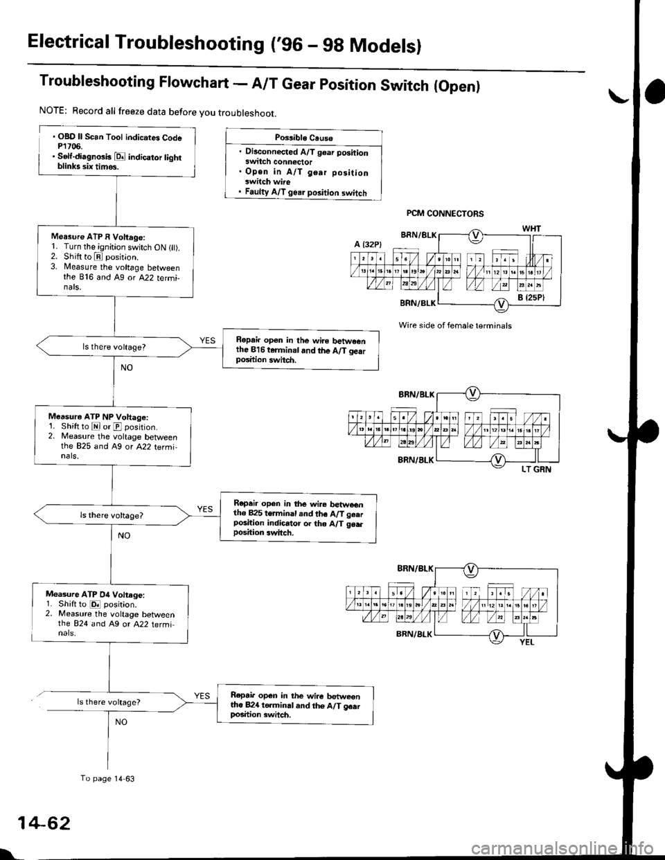
Electrical Troubleshooting ('96 - gg Modelsl
Troubleshooting Flowchart - A/T Gear position Switch (Open)
. OBD ll Scan Tool indicates CodeP1706.. Self-di.gnosk E indicator tightblinks six timos.
Measure ATP 04 Voltege:1. Shiftto E position.2. Measure the voltage betweenthe 824 and A9 or A22 terminals,
ls there voltage?
Possible Causo
. Disconnected A/T gear positionswitch conn€ctor. Open in A/T gear positionswitch wire. Faulty A/T gear position switch
Wire side of female terminals
NOTE: Record all freeze data before you troubleshoot.
Moasure ATP I Voltage:1. Turn the ignition switch ON 1 ).2. Shift to E position.3. Measure the voltage betweenthe B'f6 and Ag ot A22 tetmi-nats.
Ropai. op€n in the wire betwe€nthe Bl6 terminal.nd the A/T gearposition swhch.
Measur€ ATP NP Voltage:1. Shift to E or E position.2. Measure the voltage betweenthe 825 and A9 or A22 termi,nals,
Repeir open in the wir€ betweentho B25 terminal and th6 A/T geerposition indicator or tho A/T 96.rposition 3witch.
Rcpair open in the wire betweentto 82{ to.minal and th6 A/T geatlrosition 3witch.
To page 14 63
PCM CONNECTORS
NO
1
L
+62
Page 742 of 2189
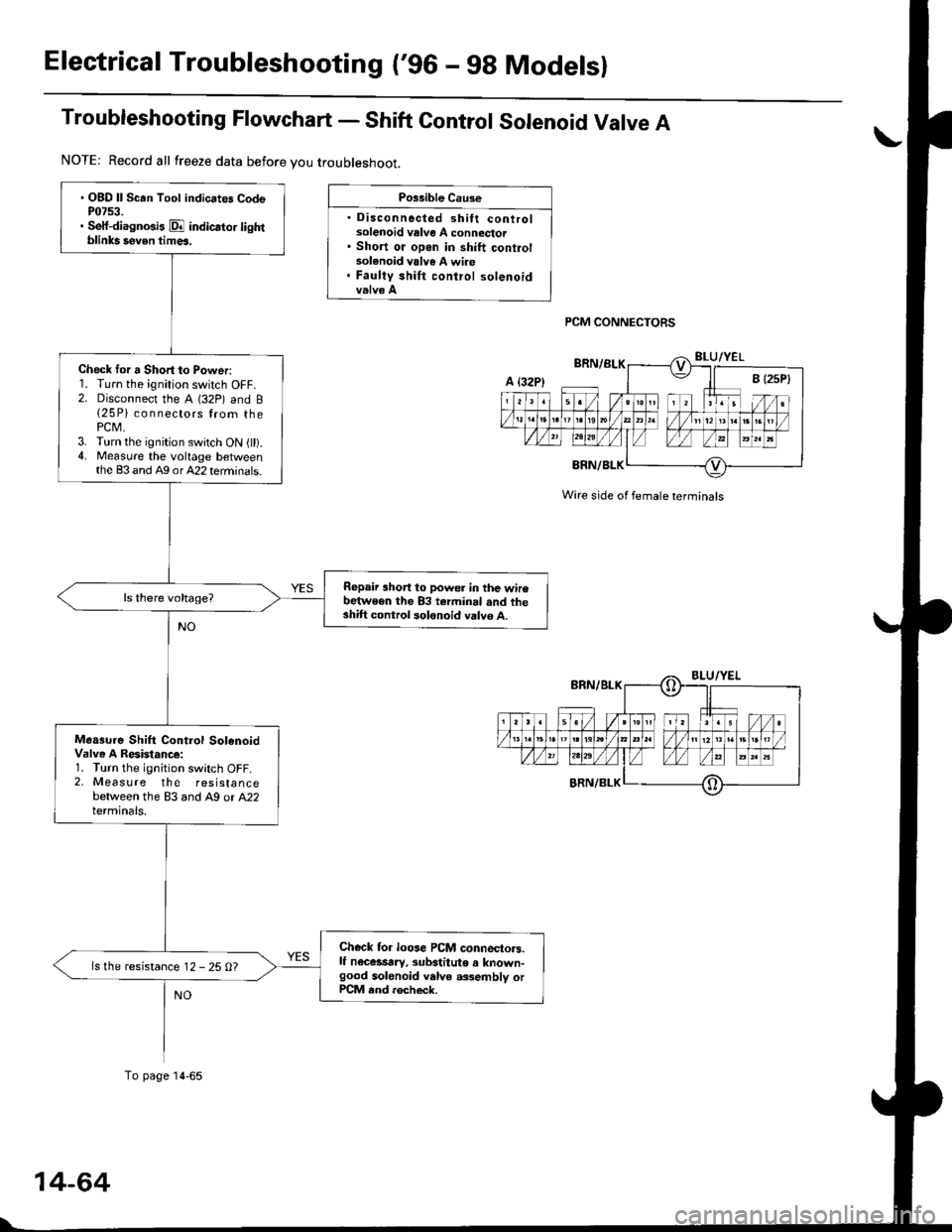
Electrical Troubleshooting ('96 - 98 Modelsl
Troubleshooting Flowchart - Shift Gontrol Solenoid Valve A
Po$ible Cau3e
. Disconnected shift controlsolenoid valve A connector. Short oi open in shift controlsolenoid valve A wire. Faulty shirt control solenoid
PCM CONNECTORS
' OBD ll Scan Tool indicates CodeP0753.. Sett{iagnosis E indicator lightblinks seven tim6.
Check tor a Short to Power:1. Turn the ignition switch OFF.2. Disconnect the A (32P) and B{25 Pi connectors trom thePCM.3. Turn the ignition switch ON {ll).4. Measure the voltage betweenthe 83 and A9 orA22 terminals.
Repair short to powe. in the wir6between the 83 terminal .nd theshift control solonoid valvo A.
Moa3ure Shift Control SolenoidValve A Resistanc€:1. Turn the ignition switch OFF.2, Measure the resistancebetween the 83 and A9 or A22terminals.
Ch€ck for loose PCM connectors.lf n€c6srry, subatitute a known-good solenoid valve a3,sembly orPCM end rocheck.
ls the resistance 12 - 25 0?
NOTE: Record all freeze data before you troubleshoot.
A t32Pl
To page 14-65
Wire side ol female terminals
Page 744 of 2189
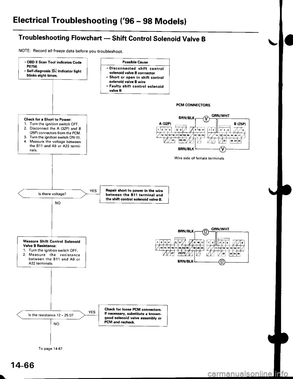
Electrical Troubleshooting ('96 - g8 Modelsl
Troubleshooting Flowchart - Shift Control Solenoid Valve B
Possible Cause
' Disconnected shift controlsolenoid valve I connectol. Short or open in shift controlsolenoid valve B wire. Faulty shift control 30lenoidvalve B
PCM CONNECTORS
Wire side ot female terminals
. OBD ll Scan Tool indic.tes CodeP0758.. Solt-diagnosis E indicator lightblinks eight times.
Chock for a Short to Power:1. Turn the ignition swatch OFF.2. Disconnect the A (32P) and B(25P)connectors from the PCM.3. Turn the ignition switch ON (ll).4. Measure the voltage betweenthe 811 and Ag or A22 termi-nals,
Repair short to powar in the wirebotwcen the 811 torminal andthe shift control solenoid valve 8.
Measure Shift Cont.ol SolenoidValve B Resktance:1. Turn the ignition switch OFF.2, Meas u re the resistancebetween the Bll and A9 orA22 terminals.
Checl for loose PiCM connector3.lf nec€ssary, sub3titute a known-good solenoid v.lve assembly olPCM and recheck.
ls the resistance 12 - 25 O?
NOTE: Record allfreeze data before you troubleshoot,
A t32P)
To page 14 67
\
Page 746 of 2189
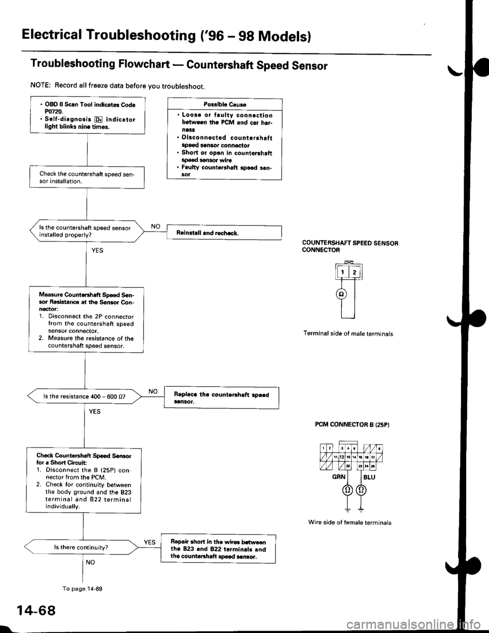
Electrical Troubleshooting ('gO - 98 Modelsl
Troubleshooting Flowchart - Countershaft Speed Sensor
Po$iblo Causa
' Loosg or laulty conncctionbotwocn tho PCM and c.i hrr-n1't!' Disconnoctad countorahottlpo€{ san3or oonnoctot. Short or opon in countorshaftspeed lonsor wire. F ulty counte.lhalt spe6d s6n-sol
COUNTERSHAFT SPEED SENSORCONNECTOR
lFI,]1-F=r
9l
L_l
Terminal side ol male terminals
PCM CONNECTOR B I25P}
1
l'
NOTE; Record allfreeze data before you troubleshoot.
. OBO ll Scln Tool indicat6 Codem7z).. S6lt-dirgnosis E indic.tollight blink! nin. tim6,
ls the countershaft spoed sensorinstalled properly?
Moa3ure CountoEhaft Sp€ed S6n-sor Reaktanc€ at tho Son3or Con-noctor1. Disconnect the 2P connectortrom the countershaft spgedsensor connector,2. Measure the resistance of thecountershaft sDeed sensor,
ls the resistance 400 - 600 0?
Chock Countersh.ft Spood Scr|3olfor a Shoft Circuit:1. Disconnect the B {25P) connector from the PCM.2. Check for continuity betweenthe body ground and the 823terminal and 822 terminalindividually.
Repai. .hort in th. wiroa b.t$re€ntho 823 lnd 822 torminals .ndlho counteBhaft lpocd aenro..
To page 14-69
4-68
Wire side of temale terminals
Page 758 of 2189
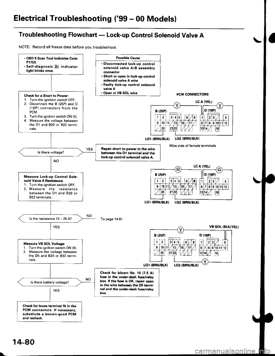
Electrical Troubleshooting ('99 - 00 Models)
Troubleshooting Flowchart - Lock-up Control Solenoid Valve A
NOTE: Record all freeze data before vou troubleshoot.
Possible Cause
. Disconnocted lock-uD controlsolenoid valve A/B alsemblyconnector. Short or opon in lock-up conkolsolenoid valv6 A wire. Faulty lock-up control solenoidvalva A' Open in VB SOL wireFCM CONNECTORS
LGl IBRN/BLXI LG2 (BRN/BLK)
Wire side ot female terminals
LGl (BRN/BLKILG2 IBRN/8LK)
To page 1+81
a\
. OBD ll Scan Tool indic.t6 CodeP1753.. Self-diagnosis @ indicatorlight blink3 once.
Check lor a Short to Power:L Turn the ignition switch OFF.2. Disconnect the B (25P) and D(16P) connectors lrom thePCt\4.3. Turn the ignition switch ON (ll).4. Measure the voltage betweenthe Dl and 820 or 822 termi-nats.
Ropair short to powcr in the wirebstwoon tho Dl tolminal and thelock-up cor|lrol lolonoid valvo A.
Measu.e Lock-up Cont.ol Sole-noid V.lvo A R63btanc6:1. Turn the ignition switch OFF.2. Measure the resistancebetween the Dl and 820 or822 terminals.
ls the resistance 12 - 25 O?
Measure VB SOL Vohage:1. Turn the ignition switch ON (ll).2. Measure the voltage betweenthe D5 and 820 or 822 termi-nals.
Check for blown No. 15 17.5 Alfu3€ in the undordash fuse/rabybox. l{ th€ tusa ii OK, r.pair oponin the wira b€twoen th€ 05 torfti-nal and thc und€r{ash fuso/r€laybox.
Check to.loose tarminalfit in thePCM connecloa3. ll necessary,substilute a known-good PCMand rocheck.
B (25Pt ll D {16P1
B (2sPt ll D {16P1
I t25Pt D (16P1
l..
14-80
Page 760 of 2189
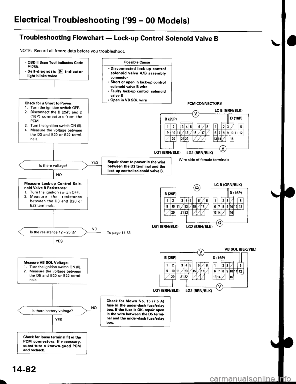
Electrical Troubleshooting ('99 - 00 Models)
Troubleshooting Flowchart - Lock-up Control Solenoid Valve B
NOTE| Record allfreeze data before you troubleshoot.
Possibla Cause
. Oisconnected lock-uD controlsolenoid velve A/B assemblyconnector. Short or open in lock-up controlsolenoid valv€ B wire. Faulty lock-up control solenoidvalve B' Open in VB SOL wirercM CONNECTORS
To page 14-83
' OBD ll Scan Tool indic.tes CodeP1758.. Self-diagnosis E indicatorlight blinks twice.
Chack for a Short to Power:1. Turn the ignition switch OFF.2. Disconnect the I (25P) and D(16P) connectors from thePCM.3. lurn the ignition switch ON (ll).4. Measure the voltage betweenthe D3 and 820 ot 822 tetmi-nals,
Repair short to power in the wirebetween the D3 terminal and thelock-up contlol solenoid valve B.
Measure Lock-up Control Sole-noid Vdlve I R8i3tance:1. Turn the ignition switch OFF.2, Measure the resistancebetween the D3 and 820 or822 terminals.
ls the resistance 12 - 25 O?
Measure VB SOL Voltago:1. Turn the ignition switch ON lll).2. Measure the voltage betweenthe D5 and 820 or 822 termi-nals.
Check for blown No. 15 {7.5 Alfus€ in the under-dash luse/releybox. It the fuse is OK, repair openin the wir6 between th6 DS terminal and the under-dash fuse/rebyoox,
ls there battery voltage?
Chock for loose te.minal fit in thePCM connectors. It necessary,substitute a known-good PCMend recheck.
B t2sP) ll D t15P)
Wire side ol female terminals
I {2sPt ll D (16Pt
B (25P1 D t16Pt
\
14-82
Page 762 of 2189
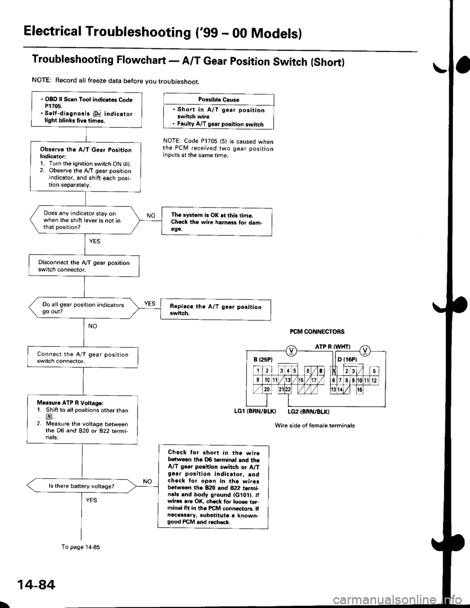
Electrical Troubleshooting ('gg - 00 Models)
Troubleshooting Flowchart - A/T Gear position Switch (Short)
NOTE: Record all freeze data before you troubleshoot.
Po$ible Cause
' Short in A/T go.r positionswhch wire. Faulty A/T goar position switch
NOTE: Code P1705 (5)the PCM received twoinputs at the same time.
is caused whengear position
PCM CONNECTORS
LGl (BRN/BLK) LG2 (BRN/BLKI
Wire side of femaleterminals
B {25P1 llD (16P1
. OBD ll Scan Tool indicrtB CodeP1?05.. Solt-diagno3i3 E indicatorlight blink. tive times.
Observo the A/T Gear PositionIndicetori1. Turn the ignition switch ON fit).2. Observe the lVT gear positionindicator, and shift each posi,!on separately.
Does any indicator stay onwhen the shift lever is not inthat position?
The sFtom is OK at thi3 time.Check the wi.e harness for dam-aga.
Do all gear position indicatorsgo out?
Moasure ATP R Voltage:1. Shift to all positions otherthanE.2. Measure the voltage betweenthe DG and 82O o( 822 terfii-nats.
Check tor short in the wirebatwoen tha DB terminal and theA/T go.r porhion switch or A/Tg6ar po3ition indicator, andchock for opon in the wiresbetween the B20 and B22 t€rmi-n.ls and body ground (G10 . tfwir€c rro OK, chsck fo. loo3e tel-ftinal fit in the FCM connectors. llnoceisary, substiiute e known-good FCM and r€check.
ls there battery voltage?
To page 14-85
\
14-84
Page 765 of 2189
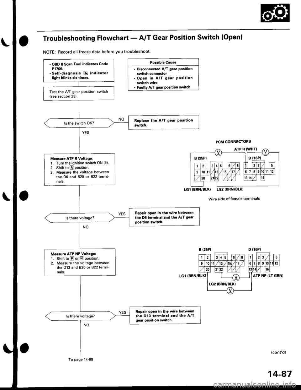
Troubleshooting Flowchart - A/T Gear Position Switch (Open)
NOTE: Record allfreeze data before you troubleshoot.
Po$ible Cause
. Disconnectod A/T goar position
switch conngdor. Open in A/T gear position
switch wire. Fautty Aft gear poshion switch
PCM CONNECTORS
Wire side of lemaleterminals
D (16P1
GRNI
B (25Pt llDtl6Pl
IARN/BLK) LG2IBRN/BLKI
2{6,|235
I't011/t5l/18912
ATP NP (LT
. OBO ll Scan Tool indicatd CodcP1706.' Sslf-diagnosis E indicatorlight blink3 six tim6.
Test the Ay'T gear position switch(see section 23).
Moasure ATP R Volt.ge:'1. Turn the ignition switch ON ('l).
2. Shift to E position.
3. Measure the voltage between
the D6 and 820 ot 822 termi'nals.
Repoir opon in the wire bitween
the D6 torminll and the A/T go.r
position switch.
Measuro ATP NP Volt ge:
1. Shift to E or E position.
2. Measlre the voltage betweenthe D13 and 820 or 822 termi-nals,
Ropair op€n in thc wire betwoonthe D13 terminrl and the A/Tge.r position switch.
LG1 {BBN/BLKI
Io page 14-88
(cont'd)
Page 767 of 2189
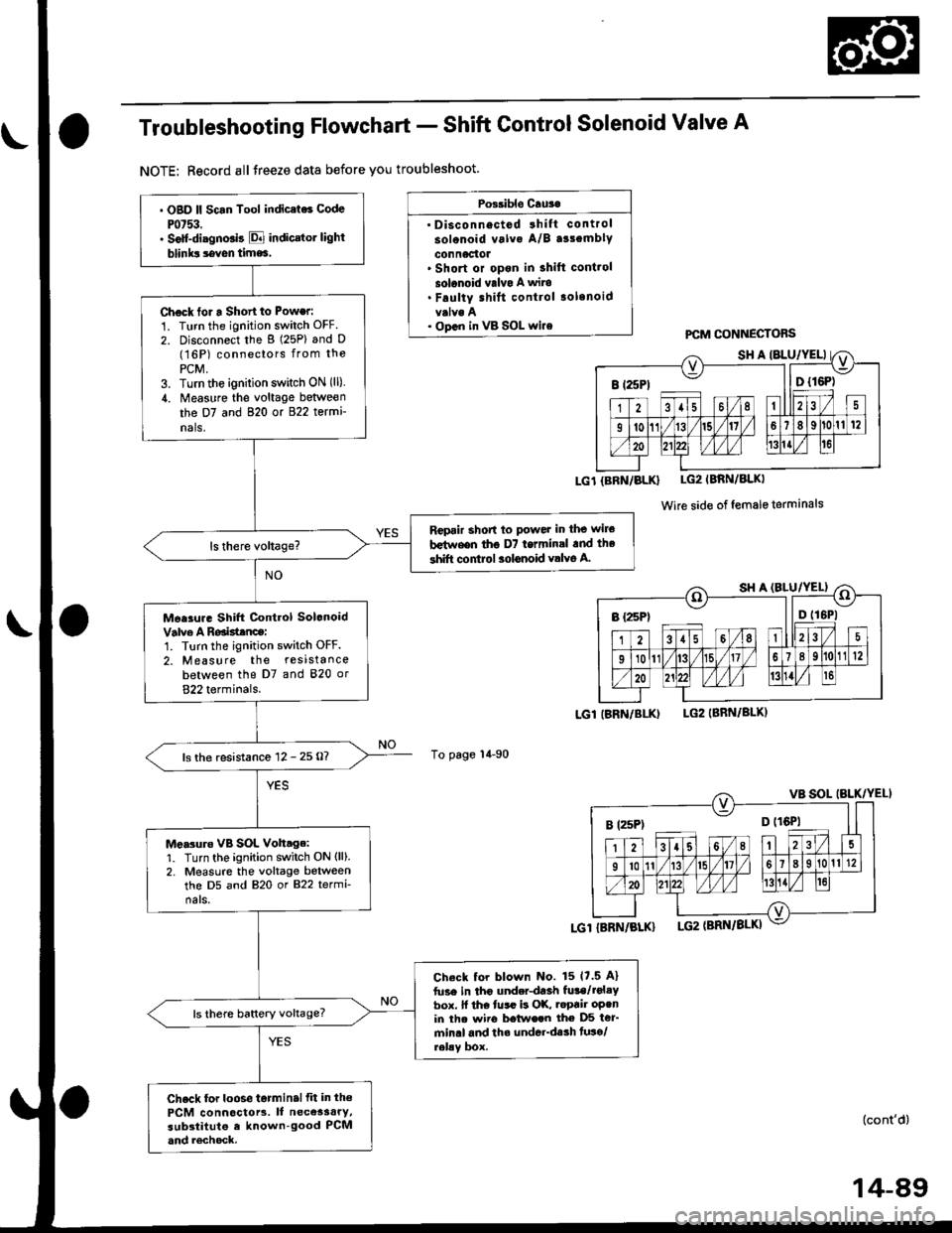
Troubleshooting Flowchart - Shift Control Solenoid Valve A
NOTE: Record allJreeze data before you troubleshoot.
Possible Cru3.
' Disconnectod 3hift control
solonoid valva A/B a33emblY
connactot. Short or opon in shift cont.ol
solonoid valvo A wits. Faulty shift control .olenoid
. op.n in vB SOL wi.e
To page 14-90
PCM CONNECTOBS
LG1{BRN/BLK} LG2IBRN/BLKI
Wire side of female terminals
LGl IBRN/BI-K)LG2IBBN/BLK)
. OBD ll Scan Tool indic.ts6 Code
Pot53.. Solt-diagno.is E indicrtot light
blinks seven time6.
Chock tor a Short to Power:
1. Turn the ignition switch OFF.
2. Disconnect the g (25P) and D(16P) conneclors from the
PCM,3. Turn the ignirion switch ON (ll)
,1. Measure the voltage between
the D7 and 820 or 822 termi
nals,
Rcpair short to powet in the wile
b€t^reen tho D7 termin.l .nd the
shift control aolonoid valve A.
Mee3ur. Shift Control Solonoid
Valve A Roaisttnce:1. Turn the ignition switch OFF.
2. Measure the resistance
between the D7 and 820 or
822 terminals.
ls the resistance 12 - 25 O?
Me.3uro vB SOL Voh.ge:1. Turn the ignition switch ON (ll).
2. Measure the voltage betweenthe D5 and 820 or 822 termi-
nals.
Check tor blown No. 15 17.5 A)
fuse in tho underdaah fula/rol.Ybox. ll the tusr is OK, .epair oPenin th. wiio betwe.n the D5 ter'min.l and th. underdssh tuso/relav box.
ls there baftery voltage?
Check for loose t6tminalfit in th€
PCM connoctors. It necessary,substitute e known-good PCMand rechock.
I t25Pt ll D {16P)
B rzsPt o trQil
(cont'd)
14-89