check engine HONDA CIVIC 1998 6.G Workshop Manual
[x] Cancel search | Manufacturer: HONDA, Model Year: 1998, Model line: CIVIC, Model: HONDA CIVIC 1998 6.GPages: 2189, PDF Size: 69.39 MB
Page 500 of 2189
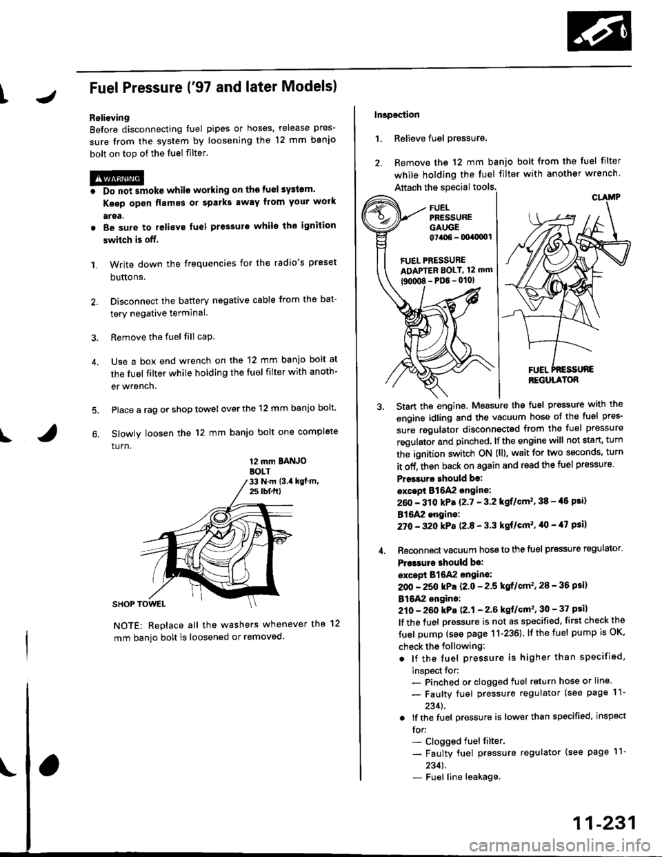
tJFuel Pressure {'97 and later Models)
ReliGving
Before disconnecting tuel pipes or hoses, release pres-
sure from the system by loosening the 12 mm banjo
bolt on top of the fuel filter.
@o Do not smoke whilo working on the fuel sy3lom.
Ksgp op€n flames or sparks away tlom Your work
arga.
. Be sure to relieve fuel pressule while the ignition
swhch is off.
1. Write down the frequencies for the radio's preset
buttons,
2. Disconnect the battery negative cable from the bat-
tery negative terminal.
3. Remove the fuel fill cap.
Use a box end wrench on the 12 mm banjo bolt at
the fuel filter while holding the fuel filter with anoth-
er wrench.
Place a rag or shop towel over the 12 mm banio bolt.
Slowly loosen the 12 mm banjo bolt one complete
turn.
4.
I
12 mm BAtt OBOLT33 N.m (3.i1 kgf m,25 tbf.f0
NOTE: Replace all the washers whenever the 12
mm banio bolt is loosened or removed.
Inspaqtion
1. Relieve fuel pressure.
2. Remove the 12 mm banjo bolt from the fuel filter
while holding the fuel Jilter with another wrench
Attach the special tools.
3. Start the enginethe fuel Pressure with the
engine idling and the vacuum hose of the fuel pres-
sure regulator disconnected from the fuel pressure
regulator and pinched lfthe engine will not start, turn
the ignition switch ON {ll), wait for two seconds, turn
it off, then back on again and read the fuel pressure'
Pr$3uro ehould be:
excepi 816A2 sngine:
260 - 310 kPa {2'7 - 3.2 kgf/cm" 38 - {6 Fi}
B16A2 engine:
27O -32O kPa P.8 - 3'3 kgf/cm'�, '10 - 47 psi)
4. Reconnect vacuum hoso to the fuel pressure regulator'
Pre33ure 3hould be:
except B16A2 engin€:
2OO - 250 kPa {2.0 - 2'5 kgf/cm'�, 28 - 36 psi)
B16A2 engino:
210 - 260 kPa 121 - 2.6 ksf/cm'�, 30 - 37 psi)
lf the fuel pressure is not as specified, first check the
fuel pump (see page 11-236) lfthetuel pumpisoK,
check tho following:
. lf the fuel pressure is higher than specified,
inspect for:- Pinched or clogged fuel return hose or line.
- Faulty fuel pressure regulator (see page 11-
2341.
. lf the fuel pressure is lower than specified, inspect
for:- Clogged fuel filter.
- Faulty fuel pressure regulator (see page l1-
2341.- Fuel line leakage.
FUEL PRESSUREADAPTER BOLT, 12 mm
tguxt8-PD6-0101
CLAMP
REGULATOR
11-231
Page 502 of 2189
\J
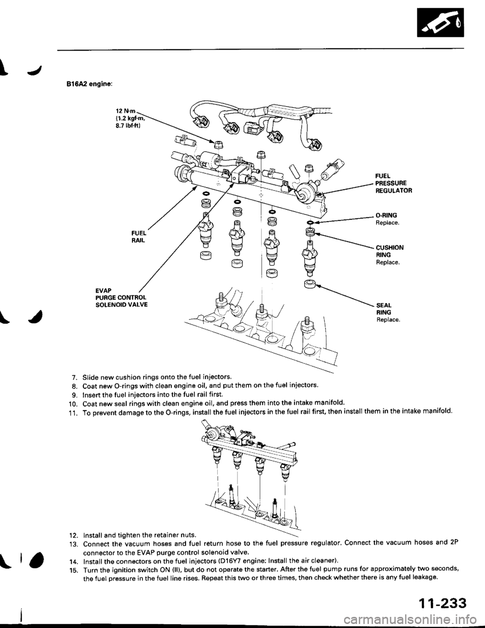
81642 engine:
EVAP
12 N.m
{1.2 kgl m;8.? lbt.ft)
FUELPRESSUREREGULATOR
O.RINGReplace.
cusHloNRINGReplace.
PURGE CONTROLSOLENOID VALVE
\
SEALRINGReplace.
7. Slide new cushion rings onto the fuel injectors.
8. Coat newO-ringswith clean engineoil, and putthem onthefuel injectors.
9. Insert the fuel injectors into the fuel rail first.
10. Coatnewseal rings with clean engine oil,and press them intothe intake manifold.
11. To prevent damage to the O-rings, installthe fuel injectors inthefuel rail first, then install them inthe intake manifold.
'12. Install and tighten the retainer nuts.
13. Connect the vacuum hoses and fuel return hose to the fuel pressure regulator, Connect the vacuum hoses and 2P
connector to the EVAP purge control solenoid valve.
14. Install the connectors on the fuel inl'ectors (D16YI engine; Install the air cleaner).
15. Turn the ignition switch ON (ll), butdo not operate the starter. After the tuel pump runs for approximately two seconds,
the fuel pressure in the fuel line rises. Repeat this two or three times, then check whether there is any fuel leakage.
11-233
Page 503 of 2189
Fuel Supply System
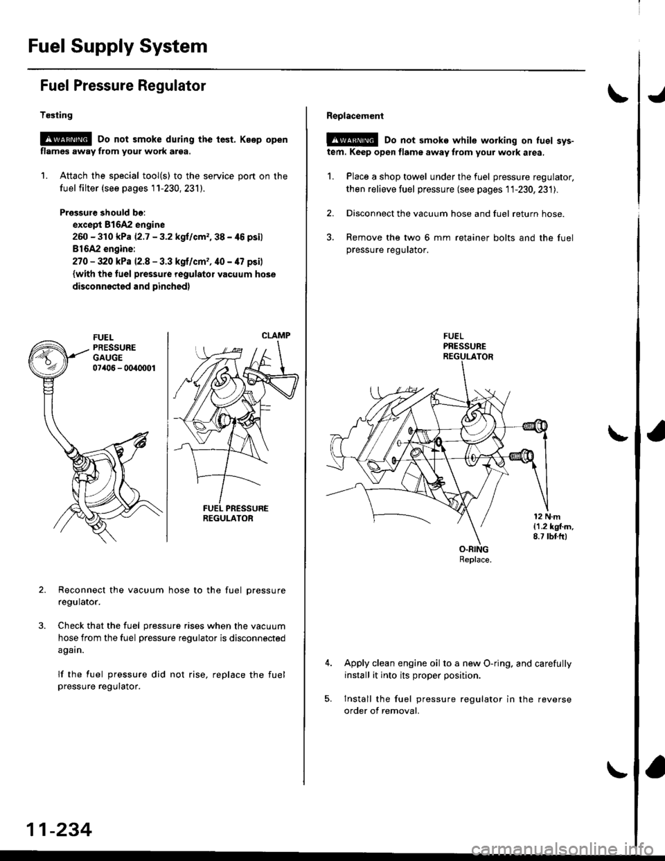
Fuel Pressure Regulator
Te3ting
@ Do not smoke during the tast. Keep open
flamcs away from your work arsa.
1. Attach the special tool(s) to the service port on the
fuel filter (see pages 1 1-230, 231).
Pressure should bo:
except 81642 engine
260 - 310 kPa |'2.7 - 3.2 kgllcrn2,38 - /t6 psil
816A2 engine:
27O - 320 kPa 12.8 - 3.3 kgf/cm,, 40 - 47 psi)
{with the tuel pressure regulator vacuum hose
disconnested and pinched)
Reconnect the vacuum hose to the fuel pressure
regulator.
Check that the fuel pressure rises when the vacuum
hose from the fuel pressure regulator is disconnected
again.
lf the fuel pressure did not rise, replace the fuel
pressure regutalor.
CLAMP
REGULATOR
11-234
Reolacement
@@ Do not smoke while working on luel sys-
tem. Keep open flame away from your work area,
1. Place a shop towel under the fuel pressure regulator,
then relieve fuel pressure (see pages 11-230,231l..
2. Disconnect the vacuum hose and fuel return hose.
3. Remove the two 6 mm retainer bolts and the fuel
pressure regurator.
Apply clean engine oil to a new O-ring. and carefully
install it into its proper position.
Install the fuel pressure regulator in the reverse
order of removal.
Page 506 of 2189
I
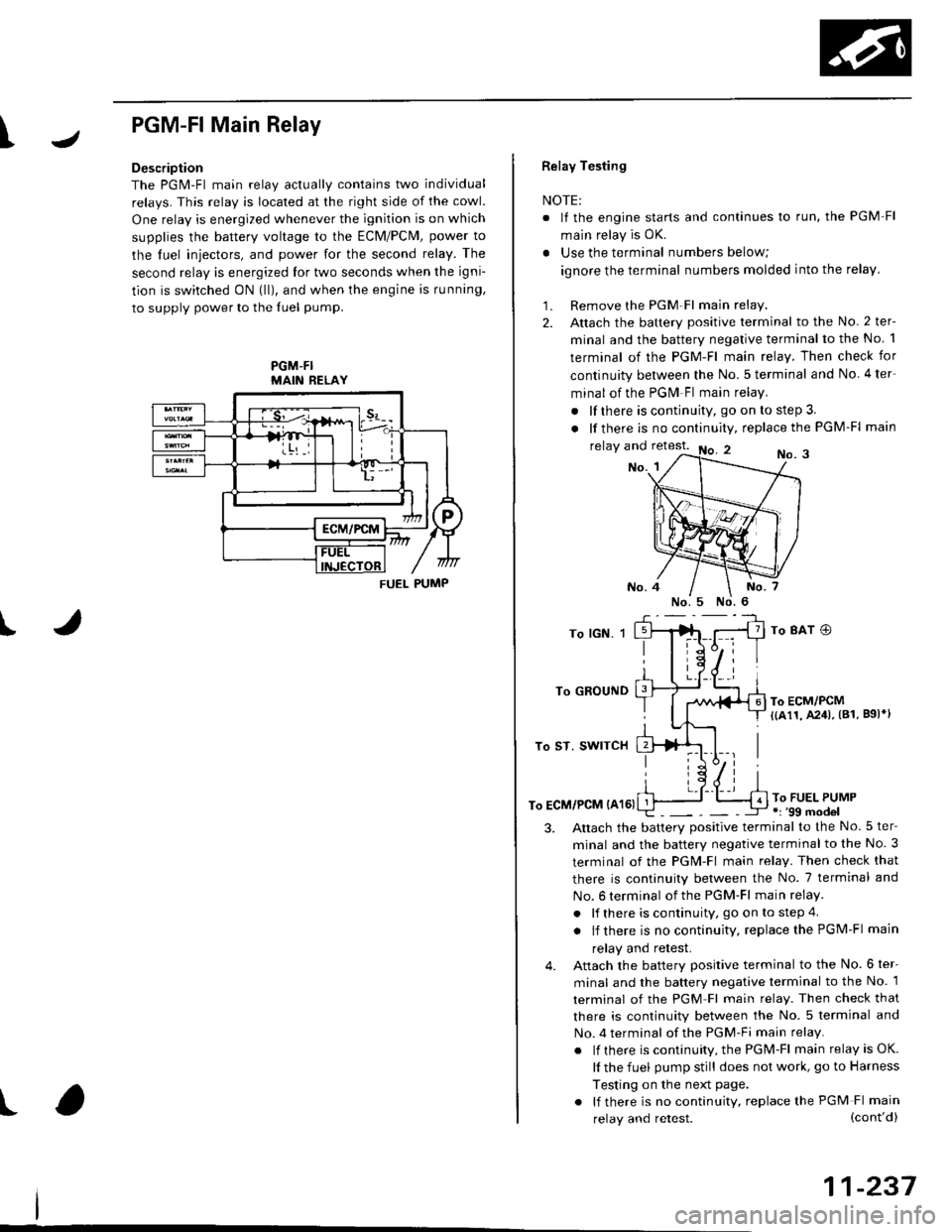
PGM-FlMain Relay
Description
The PGM-Fl main relav actuallv contains two individual
relays. This relay is located at the right side of the cowl.
One relay is energized whenever the ignition is on which
supplies the battery voltage to the ECM/PCM, power to
the luel iniectors, and power for the second relay. The
second relay is energized lor two seconds when the igni-
tion is switched ON (lll, and when the engine is running,
to supply power to the luel pump.
PGM-FIMAIN RELAY
J
I
t
FUEL PUMP
Relay Testing
NOTE:
. It the engine starts and continues lo run. the PGM Fl
main relay is OK.
. Use the terminal numbers below;
ignore the terminal numbers molded into the relay,
1. Remove the PGM Fl main relay.
2. Attach the battery positive terminal to the No. 2 ter-
minal and the battery negative terminal to the No 1
terminal of the PGM-Fl main relay. Then check for
continuity between the No.5 terminal and No 4ter-
minal of the PGM Fl main relay.
. lf there is continuity, go on to step 3.
. lf there is nocontinuity, replacethe PGM-Fl main
relay and retest.No. 3No. 1
To lGN. 1
To GROUND
To ST. SWITCH
To ECM/PCM {A161
To 8AT O
To ECM/PCM{(a11, A241, (81. B9l*l
To FUEL PUMP.r '99 model
3.Altach the batterv positive terminal to the No.5 ter-
minal and the battery negative terminal to the No. 3
terminal of the PGM-Fl main relay. Then check that
there is continuity between the No. 7 terminal and
No. 6 terminal of the PGM-Fl main relay.
. lf there is continuity, go on to step 4
. lf there is nocontinuity, replacethePGM-Fl main
relay and retest.
Attach the battery positive terminal to the No. 6 ter-
minal and the battery negative terminal to the No. 1
terminal of the PGM Fl main relay. Then check that
there is continuity between the No. 5 terminal and
No. 4 terminal of the PGM-Fi main relay.
. lf there is continuity, the PGM-Fl main relay is OK.
lf the fuel pump still does not work, go to Harness
Testing on the next page.
. lf there is no continuity, replace the PGM Fl main
4.
(cont'd)
11-237
relay and retest.
Page 507 of 2189
Fuel Supply System
PGM-FI Main Relay (cont'dl
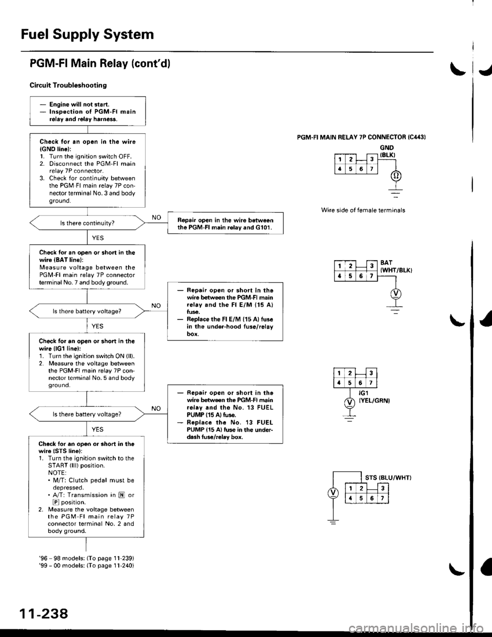
Circuit Troubleshootin g
PGM.FI MAIN RELAY 7P CONNECTOR {C443)
GND{8LK)
Wire side of female terminals
/BLK}
- Engine will not start.- lnsoection of PGM-FI mainrelay and relay harne$.
Check for an open in the wire{GNO line}:l. Turn the ignition switch OFF.2. Disconnect the PGM-Fl mainrelay 7P connector.3. Check for continuity betweenthe PGM Fl main relay 7P con-nector terminal No.3 and bodyground.
Ropai. open in the wir€ betweenthe PGM-FI main .elav and G101.
Check for an open or short in thewire {BAT lin€}:N4easure voltage between thePGM-FI main relay 7P connectorterminal No. 7 and body ground.- Repair open or sho.t in thewire between the PGM-FI mainrelay and the Fl E/M {15 A}fus€.- Replace the Fl E/M (15 Allu3ein the under-hood fuse/relayoox.
ls lhere battery voltage?
Check tor an open or short in thewire {lGl line):1. Turn the ignition switch ON (ll).
2. Measure the voltage betweenthe PGM-Fl main relay 7P con'nector terminal No. 5 and bodyground.- Repair open or short in thewire betwoen the PGM-FI mainrelav and the No. 13 FUELPUMP (15 A)tuse.- R€place the No. 13 FUELPUMP {15 A} tus€ in the under-d.sh fus€/relay box.
ls there battery voltage?
Ch.ck for an open or short in thewire {STS lino}r1. Turn the ignition switch to theSTART (lll) position.NOTE:. M/T: Clutch pedal must beoepresseo.. A/T: Transmission in E or
E position.2, Measure the voltage betweenthe PGM-Fl main relay 7Pconnector terminal No, 2 andbody ground.
12
[,a567
123BAT
{WHTa56,
'96 98 models: (To page 1l 239)'99 - 00 models: (To page I l-240)
11-238,
Page 513 of 2189
lntake Air System
Air Cleaner (ACLI
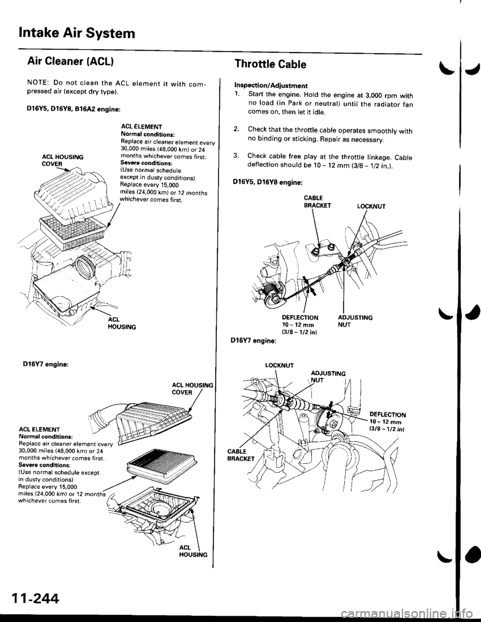
NOTE: Do not clean the ACL element it with com-pressed air {except dry type).
D16Y5, D16Y8, 816A2 engine:
ACL ELEMENTNormal conditions:Replace air cleaner element every30,000 miles (48,000 km) or 24months whichever comes first.S€voae conditions:(Use normal scheduleexcept in dusty conditions)Replace every 15,OOOmiles (24,000 km)or 12 monthswhichever comes first.
D16Y7 engine:
ACL ELEMENTNormal conditions:Replace air cleaner element every30,000 miles (48,000 km) or 24months whichever comes first,Seve.s conditions:(Use normal schedule exceptin dusty conditions)Replace every l5,000
whichever comes first.
11-244
Throttle Cable
Inspection/Adiustment
1. Start the engine. Hold the engine at 3,000 rpm withno load (in Park or neutral) until the radiator fancomes on, then let it idle.
2. Check that the throftle cable operates smoothly withno binding or sticking. Repair as necessary.
3. Check cable free play at the throttle linkage. Cabledeflection shoutd be 10- l2 mm (3/B - 112 in.l.
D16Y5, D16Y8 engine:
CABLEBRACKETLOCKNUT
DEFLECTION10-12mm
BIA- 112 inl
D16Y7 engine:
LOCKNUT
DEFLECTION10- 12 mml3lA - lninl
Page 514 of 2189
\J
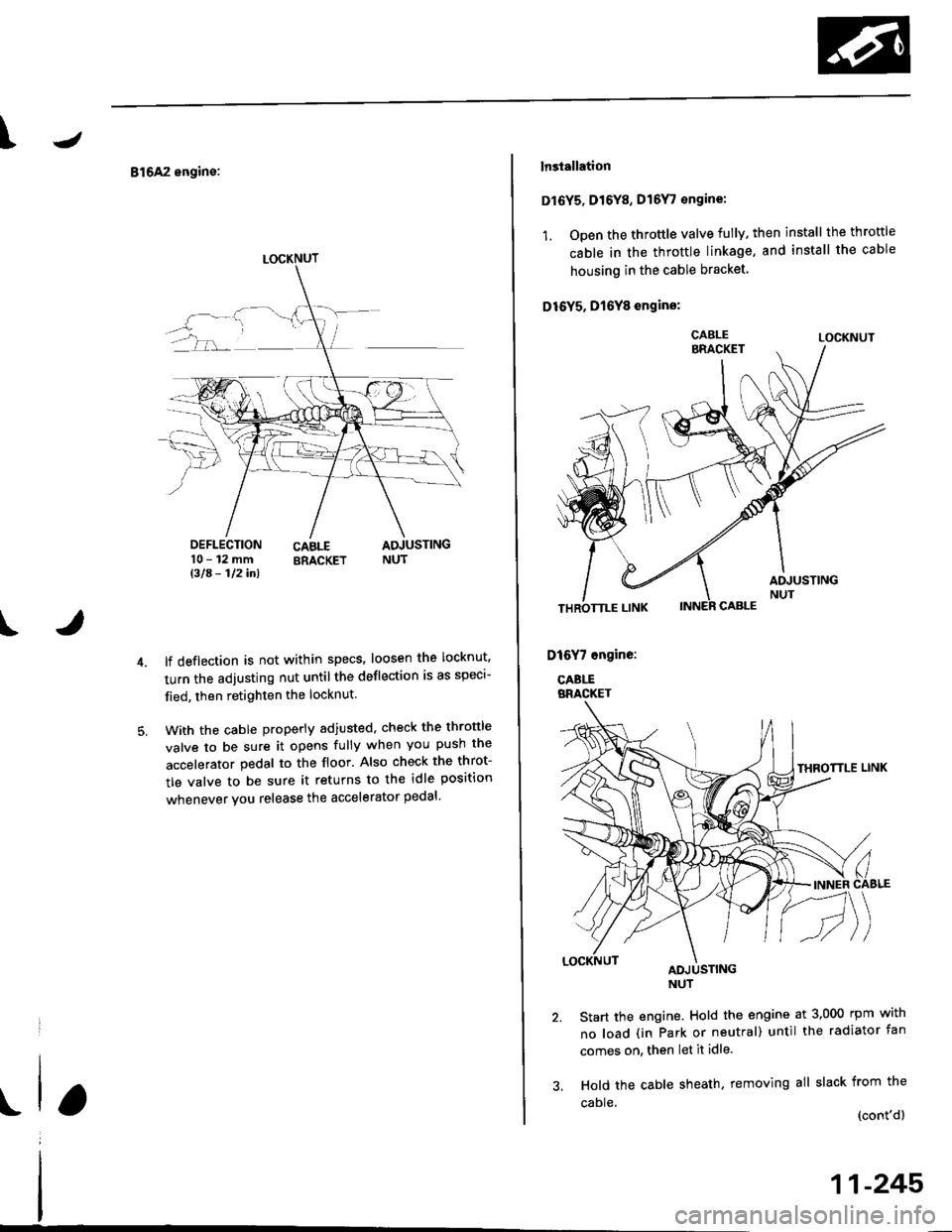
816A2 engine:
DEFLECTION10-12mmBla- 112inl
CABLE ADJUSTINGBRACKET NUT
t
lf deflection is not within specs' loosen the locknut'
turn the adjusting nut untilthe deflection is as speci-
fied, then retighten the locknut.
With the cable properly adiusted, check the thronle
valve to be sure it opens fully when you push the
accelerator pedal to the floor. Also check the throt-
tle valve to be sure it returns to the idle position
whenever you release the accelerator pedal'
LOCKNUT
lnstallation
Dl6Y5, Dr6Y8, D16Y, €ngine:
1. Open the throttle valve fully, then install the throttle
cable in the throttle linkage, and install the cable
housing in the cable bracket.
D16Y5, D16Y8 engins:
LOCKNUT
Start the engine. Hold the engine at 3,000 rpm with
no load (in Park or neutral) until the radiator fan
comes on, then let it idle.
Hold the cable sheath. removing all slack from the
caDle (cont'dl
11-245
Page 516 of 2189
IThrottle BodY
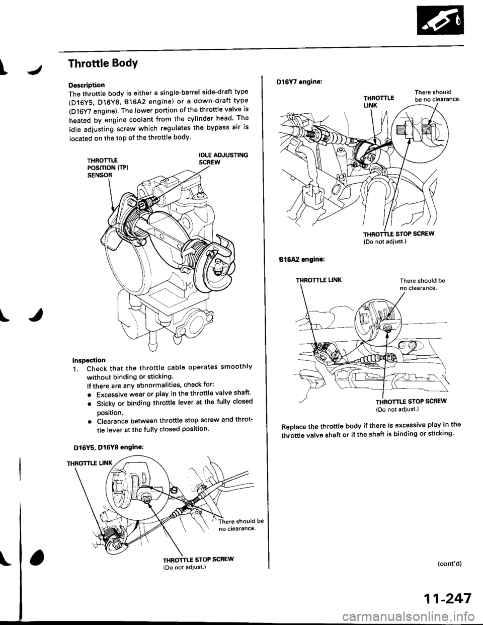
Description
The throttle bodY is either a single-barrel side-draft type
(D16Y5, D16Y8, 816A2 engine) or a down-draft type
(D16Y/ engine). The lower portion ot the throttle valve is
heated by engine coolant from the cylinder head' The
idle adjusting screw which regulates the bypass air is
located on the top of the throttle body
THROTTLEPOS|T|ON lTPlSENSOR
IDLE AD.'USTINGSCREW
t
In3pection
1. Check that the throttle cable operates smoothly
without binding or sticking.
lf there are any abnormalities, check for:
. Excessive wear or play in the throttle valve shaft'
. StickY or binding throttle lever at the fully closed
Position.. Clearance between throttle stop screw and throt-
tle lever at the fully closed position'
D16Y5, Dl6Y8 engine:
THROTTLE STOP SCREW
{Do not adjust.)
Dl6Y7 ongine:
816A2 engins:
THROTTLE LINK
STOP SCREW
THROTTTE STOP SCREW(Do not adjust.)
Replace the throftle body if thsre is excessive play in the
throttle valve shaft or iJ the shaft is binding or sticking'
(cont'd)
11-247
{Do not adjust.)
Page 520 of 2189
\J
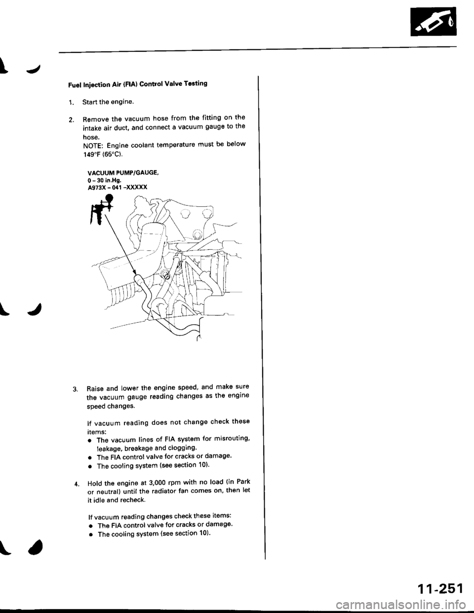
Fuol Iniection Air {FlA) Contlol Valve T$ting
1. Start the engine.
2. Remove the vacuum hose from the fitting on the
intake air duct, and connect a vacuum gauge to the
nose.
NOTE: Engine coolant temperature must be below
149"F (65"C).
VACUUM PUMP/GAUGE,
0-30 in.Hg.A973X - 041 -XXXXX
Raise and lower the engine speed, and make sure
the vacuum gauge reading changes as the engine
speed changes.
lf vacuum reading does not change check these
rtems:
. The vacuum lines of FIA system for misrouting,
leakage, breakage and clogging.
. The FIA controt valve for cracks or damage
. The cooling system (see section 10).
Hold the engine at 3,OOO rpm with no load (in Park
or neutral) until the radiator fan comes on, th€n let
it idle and recheck.
lf vacuum reading changes check these items:
a The FIA control valve for cracks or damage.
. The cooling system (see section 10).
11-251
Page 521 of 2189
Emission Gontrol System
System Description
The emission control system includes a Three Way Cata-lytic Convener (TWC), Exhaust Gas Recirculation (EGR)
system,. Positive Crankcase Ventilation (pCV) system andEvaporative Emission (EVAP) Control system. The emis-sion control system is designed to meet federal and stateemission standards.*: D16Y5 engine
Tailpipe Emission
Inspestion
@@ Do not smoke during ihis procedure. Keepany open flame away from your work area.
1. Start the engine. Hold the engine at 3,000 rpm withno load (in Park or neutral) until the radiator fancomes on. then let it idle.
2. Connect a tachometer.
Check and, if necessary, adjust the idle speed (see
page 11-220 - 223).
Warm up and calibrate the CO meter according to themeter manufacturer's instructions.
Check idle CO with the headlights, heater blower,rear window defogger, cooling fan, and air condition-er off.
NOTE: (Canada) Pull the parking brake lever up.Start the engine, then check that the headlights areoff.
CO mete. should indicate 0.1% maximum.
NOTE: '98 Dl6Y5 engine - lf the idle speed incress-es to 8101 50 rpm, this means the EVAp system ispurging the canister. To stop the purging temporari-ly. raise the engine speed above 1,000 rpm with theaccelerator pedal, then slowly release the pedal.
11-252
eFORWARD -
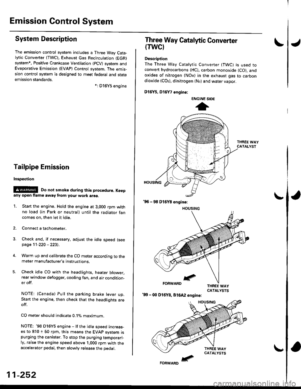
Three Way Catalytic Converter
(TWCI
Doscription
The Three Way Catalytic Converter (TWC) is used toconven hydrocarbons (HC), carbon monoxide (CO), andoxides of nitrogen (NOx) in the exhaust gas to carbondioxide (COr), dinitrogen (N,) and water vapor.
D15Y5, D16
, engine:
'99 - 00 D16Y8, 81642 engine:
ENGINE SIDE
t