Block bolt HONDA CIVIC 1998 6.G Owner's Manual
[x] Cancel search | Manufacturer: HONDA, Model Year: 1998, Model line: CIVIC, Model: HONDA CIVIC 1998 6.GPages: 2189, PDF Size: 69.39 MB
Page 1167 of 2189
Front Brake Caliper
It
Disassembly
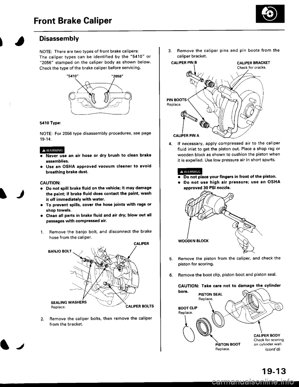
NOTE: There are two types of front brake calipers:
The caliper types can be identified by the "5410" or"2056" stamped on the caliper body as shown below.
Check the type of the brake caliper before servicing.
5410 Type:
NOTE: For 2056 type disassembly procedures, see page
19-14.
@o Never use an air hose ot dry brush to clean brakg
assemblies.
. Use an OSHA approved vacuum clganer to avoid
breathing brake dust.
CAUTION:
. Do not spill brake lluid on the vehicls; it may damage
the paint; if brake fluid does conlact the paint, wash
it off immedistely with waier.
. To prevenl spills, covet the hose ioin$ with rags or
shop towels.
. Clean all parts in brake fluid and air dry; blow out all
passages with compressed air.
L Remove the banjo bolt, and disconnect the brake
hose from the caliDer.
CALIPER
BANJO EOLT
SEALINGReplace.BOLTS
Remove the caliper bolts, then remove the caliper
from the bracket.
lJReplace.
3. Remove the caliper pins and pin boots from the
calioer bracket,
CALTPER PIN B CAL|PER BRACKET
CALIPER PIN A
4, lf necessary. apply compressed air to the caliper
fluid inlet to get the piston out. Place a shop rag or
wooden block as shown to cushion the piston when
it is expelled. Use low pressure air in short spurts.
@. Do not place your iingers in tront ol the piston.
. Do not use high air pressure; use 8n OSHA
approved 30 PSI nozzls,
Remove the piston from the caliper, and check the
piston for scoring.
Remove the boot clip, piston boot and piston seal.
CAUTION: Take care not to damage the cylindcr
PISTON SEALReplace.
BOOT CLIPReplace.
\,
,t. (
)PISTON BOOT
CALIPER BODYCheck for scoring
(cont'd)
19-13
Page 1168 of 2189
Front Brake Caliper
2056 Type:
@
Disassembly (cont'dl
Nevor u3e an air hos€ or dry brush to clgan brake
assomblios.
Use an OSHA approved vacuum cl6aner to avoid
braathing braks duet.
CAUTION:
. Do not spill brakefluid on ths vchicle; it may damage
the paint; if brako fluid does contact the p.int. wash
it olt immediately with wato..
. To prevsnt spills, cover the ho3o ioints whh rag3 or
shop towels.
. Cl€an all parts in brake fluid and air dry; blow out 8ll
passagss with compr63€d air.
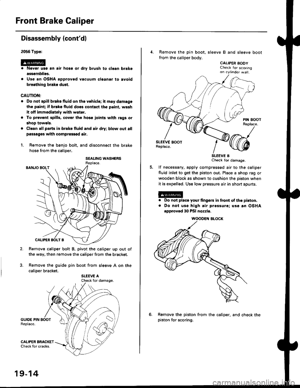
1. Remove the banjo bolt, and disconnect the brake
hose from the caliper.
SEALING WASHERS
Remove caliper bolt B, pivot the caliper up out of
the way, then remove the caliper from the bracket.
Remove the guide pin boot from sleeve A on the
caliDer bracket.
GUIDE PIN BOOTReplace.
GALIPER BRACKETCheck tor cracks.
Check for damage.
19-14
4. Remove the pin boot, sleeve B and sleeve boot
from the caliper body.
CALIPER EODYCheck for scoringon cytinder wa .
SLEEV€ BCheck for damage.
lf necessary, apply compressed air to the csliper
fluid inlet to get the piston out. Place a shop rag or
wooden block as shown to cushion the oiston when
it is expelled. Use low pressure air in short spurts,
a
a
Do not placo your lingers in ftont ol tho pkton.
Do noi usa high air prsssure; uso an OSHA
approved 30 PSI nozzle.
Remove the piston from the caliper, and check thepiston for scoring.
WOODEN ALOCK
Page 1178 of 2189
Rear Brake Pads
Inspection and Replacement
Never use an air hose or dry brush to clean brakeassemblies.
Use an OsHA-apptoved vacuum cl€aner to avoidbreathing brake dust,
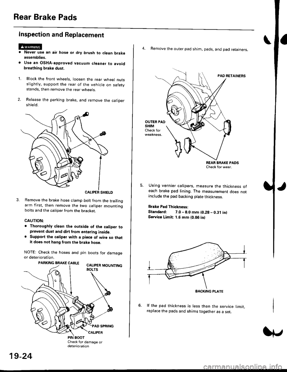
Block the front wheels, loosen the rear wneet nutsslightly, support the rear of the vehicle on safetystands, then remove the rear wheels.
Release the parking brake, and remove the calioersh ield.
CALIPER SHIELD
Remove the brake hose clamp bolt from the trailingarm first, then remove the two caliper mountingbolts and the caliper from the bracket.
CAUTION:
. Thoroughly clean the outside of the caliDer toprevent dust and dirt trom entering inside.. Support the calipor with a pieco of wire so thatit does not hang fuom the brake hose.
NOTEr Check the hoses and pin boots for damageor deterioration.
PARKING BRAKE CABLE ^.. ._-_ ---.
'L
19-24
4. Remove the outer pad shim, pads, and pad retainers.
PAO RETAINERS
OUTER PAOSHIMCheck for
REAR BRAKE PADSCheck for wear.
Using vernier calipers, measure the thickness ofeach brake pad lining. The measurement does notanclude the pad backing plate thickness.
Brake Pad Thickness:
Standard: 7.0 - 8.0 mm {0.28 - 0.31 in}Service Limit: 1.5 mm {0.06 in}
lf the pad thickness is less than the service limit,replace the pads and shims together as a set.
BACKING PI-ATE
Page 1189 of 2189
Rear Drum Brake
Index/lnspection
'1.
a
a
Never use an air hose or dly brush to clean brake assemblies,
Use an OSHA approved vacuum cleanar to avoid breathing brake dust,
Contaminated brake linings or drums reduce stopping ability.
Block the tront wheels before iacking up ths r€ar of lhe vehicle.
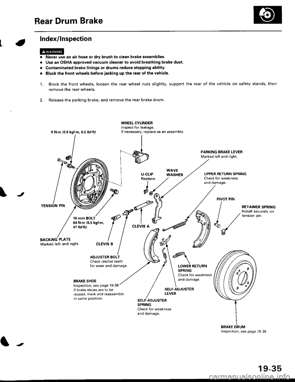
Block the front wheels, loosen the rear wheel nuts slightly, support the rear of the vehicle on safety stands, then
remove the rear wheels.
2. Release the parking brake, and remove the rear brake drum.
I N m 10.9 kgtm, 6.5 lbf.ftl
TENSION PIN
10 mm BOLT6,1N m 15.5 kgf m,47 tbf.ft)
WHEEL CYLINDERInspect for leakage.lf necessary, replace as an assembly.
u-cLrPReplace.
WAVEWASHER
PARKING BRAKE LEVERMarked left and right.
Check for weaknessano oamage,
UPPER RETURN SPRING
I
@JPIVOT PIN
BACKING PLATEMarked lelt and right-
/
€f-l.^
I I
*'t")
ctEv'sB
/ (t
/ ,.ro,".r r.*,"n
/ , Install securely on
| / tension pin.
d"/
IU
ADJUSTER BOI-TCheck ratchet teethfor wear and damage.LOWER RETURNSPRINGCheck for weaknessand oamage.BRAKE SHOEInspection, see page 19-36lf brake shoes are to bereused, mark and reassemblein same position.
SELF.ADJUSTERLEVEB
SELF-ADJUSTERSPRINGCheck for weaknessano oamage.
BRAKE DRUMInspection, see page '19 36
t
19-35
Page 1827 of 2189
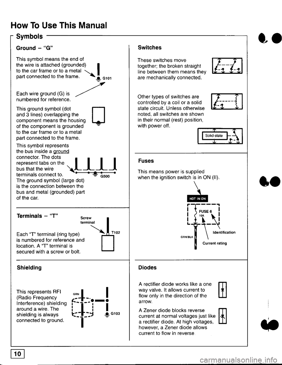
How To Use This Manual
Symbols
Ground - "G"
This symbol means the end ol
the wire is attached (grounded) Ito the car frame or to a metal I
part connected to the frame. \i oro,|
-t'
Each wire ground (G) it --/
numbered for reference.
oo
Switches
These switches move
together; the broken straight
line between them means the,
are mechanically connected.
Other types of switches are
controlled by a coil or a solid
state circuit. Unless otherwise
noted. all switches are shown
in their normal (rest) position,
with power off.
This ground symbol (dot
and 3 lines) overlapping the
component means the housing
of the component is grounded
to the car frame or to a metal
part connected to the frame.
This symbol represents
the bus inside a ground
connector. The dots I
i:l*,':1,'^:*,:"
;"
r"L I I I
terminals connect to.
The ground symbol (large dot)
is the connection between the
bus and metal (grounded) part
of the car.
Terminals - "T"
ffi
ffi
Solid-state
Fuses
This means power is supplied
when the ignition switch is in ON (ll).
Current rating
Diodes
A rectifier diode works like a one
way valve. lt allows current to
llow only in the direction of the
arrow.
A Zener diode blocks reverse
current at normal voltages just like
a rectifier diode. At high voltages.
however, a Zener diode allows
current to f low in reverse
oo
Each "T" lerminal (ring type)
is numbered for reference and
location. A "T" terminal is
secured with a screw or bolt.
Shielding
This represents RFI
(Radio Frequency
Interference) shielding
around a wire. The
shielding is always
connected to ground.
f--l;j-i",..
I
,,,,
T