Frame HONDA CIVIC 1998 6.G Owner's Manual
[x] Cancel search | Manufacturer: HONDA, Model Year: 1998, Model line: CIVIC, Model: HONDA CIVIC 1998 6.GPages: 2189, PDF Size: 69.39 MB
Page 1350 of 2189
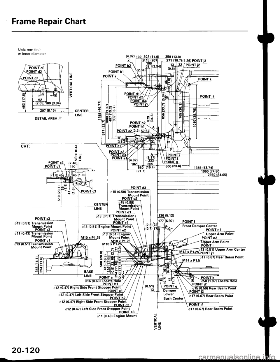
Frame Repair Chart
Unit: mm (in.)
o: Inner diameter
CVT:
DETAIL AREA.Y
(5.121
177 {6.971
20-120
Page 1368 of 2189
Reassemble in the reverse order of disassembly' and
note these items:
. Make sure the bushing and pivot washer are installed
properly.
. To connect the connecting wire, twist it 90'.
. Replace the back cover clips with new ones
. To prevent wrinkles when installing the seat-back
cover, make sure the material is stretched evenly
over the pad.
. Apply multipurpose grease to the moving portion of
the seat track.
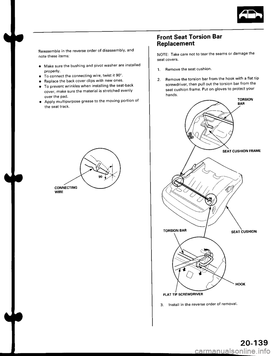
Front Seat Torsion Bar
Replacement
NOTE| Take care not to tear the seams or damage the
seat covers.
1. Remove the seat cushlon
2. Remove the torsion bar from the hook with a flat tip
screwdriver, then pull out the torsion bar from the
seat cushion frame Put on gloves to protect your
ha nds.
TORSIONSAR
SEAT CUSHION FNAME
TORSION BARSEAT CUSHION
FLAT TIP SCREWDRIVER
3. lnstall in the reverse order of removal'
20-139
Page 1411 of 2189
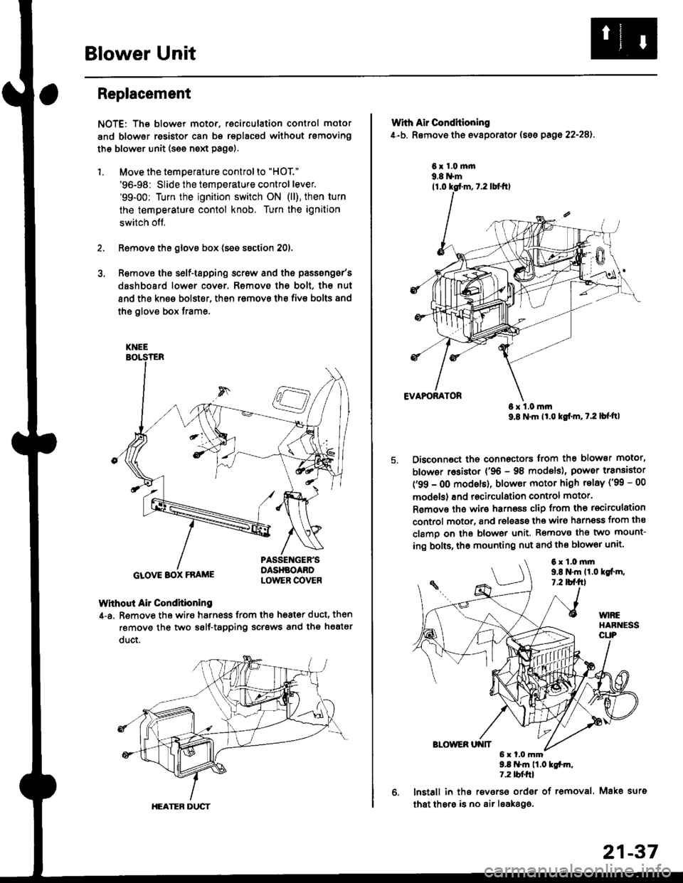
Blower Unit
Replacement
NOTE: The blower motor, recirculation control motor
and blower resistor can bs replacsd without rsmoving
th€ blower unit (see neld Page).
1. Move the temperature control to "HOT."
'96-98: Slide the temperature control lever.'99-00: Turn the ignition switch ON (ll), then turn
the temperature contol knob. Turn the ignition
switch off,
Remove the glovs box (ses ssction 20),
R€move ths s6lf-tapping screw and ths passsng6r's
dashboard low€r cover. Removo the bolt, the nut
and the kn€e bolst€r, then remove the fiv€ bolts and
the glove box trame,
Without Air Condhioning
4-a. Remove the wiro harness from the h68t€r duct, then
remove the two self-tapping scrsws and the heatsr
duct.
KNEE
GLOVE BOX FRAME
HEATER DUCT
21-37
Wrth Air Conditioning
4-b. Removo th6 ev8porator (sss pago 22-28).
6x1.0m|n9.8 N'm
6x1.0mm9.8 N'm lt'o tgf'm, t.2 lb{'ttl
Disconnoct the connectors trom th€ blower motor,
blowor r6sistor {'96 - 98 models), power transiator
('99 - 0O modsls), blowor motor high telay ('99 - 00
models) and recirculation control motor.
R€mov€ ths wiro harnoss clip from tho recirculation
control motor, and release the wir6 harnsss from ths
clamo on the blowor unit. Remove the two mount-
ing bolts, tho mounting nut and ths blowor unit'
9.8 .m 11.0 tgfm,1.2 tblfrl
lnstall in ths reverso order of removal. Mako surs
that thsre is no air leaka96.
6x1.0mm9,t N'm 11.0lgi.m,7.2 tbf.fil
Page 1452 of 2189
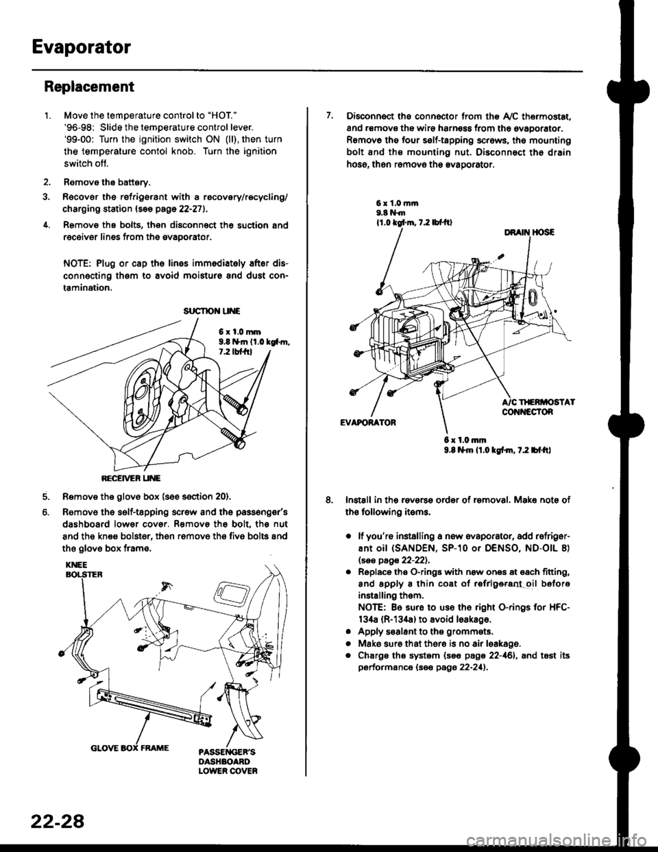
Evaporator
1.
Replacement
4.
Move the temperature control to "HOl"
'96-98: Slide the temoerature control lever.'99-00: Turn the ignition switch ON (ll), then turn
the temperature contol knob. Turn the ignition
switch off.
Remove the battsry.
Rgcover the refrigerant with a rocovery/recycling/
charging station (see page 22-271.
Remove the bolts, then disconnect th6 suction 8nd
receiver lines from th6 evaoorator.
NOTE: Plug or cap the lines imm€diatoly after dis-
connecting them to avoid moisture and dust con-
tamination.
6xl.0mm9.8 n*ln ll.0 tg6m.7.2 lbt frl
RECEiVER UNE
Remove the glov6 box (see section 20).
Removo the self-tapping scr€w and the passeng€r's
dashboard lower cover. Removs the bolt. the nut
8nd the kn€e bolst6r, th6n r6mov6 th6 fiv6 bolts and
the glove box frame.
6.
srrcrrc u E
22-28
7. Disconnect the connector from th€ Ay'C thermostat,
and r€movs the wire harness from the ovaporator.
Remov6 tho four self-tapping screws, tho mounting
bolt and ths mounting nut. Disconnect th€ drain
hose, then remov€ th6 avagorator.
6 x l.0.nm9.8 l$m lt.o ldm, 7.2 bl.tt)
Install in the reverse order of removal. Make note of
th€ following items.
o lf you'r6 installing a new evaporator, add rofriger-
ANt OiI {SANDEN, SP-10 Or DENSO, ND-OIL 8)
lsas page 22-221.
. Replace the O-rings with now ones 8t 68ch titting,
and apply 8 thin coat of r€frlgersd oil before
installing them.
NOTE: Be sure to use the right O-rings for HFC-
134a (R-134a) to avoid loakago.
. Apply s€alant to tha grommets.
. Mske sure that ther€ is no air leakage.
. Chargs ths system {s€€ page 22-161, and tost its
performance (see pags 22-211.
Page 1474 of 2189
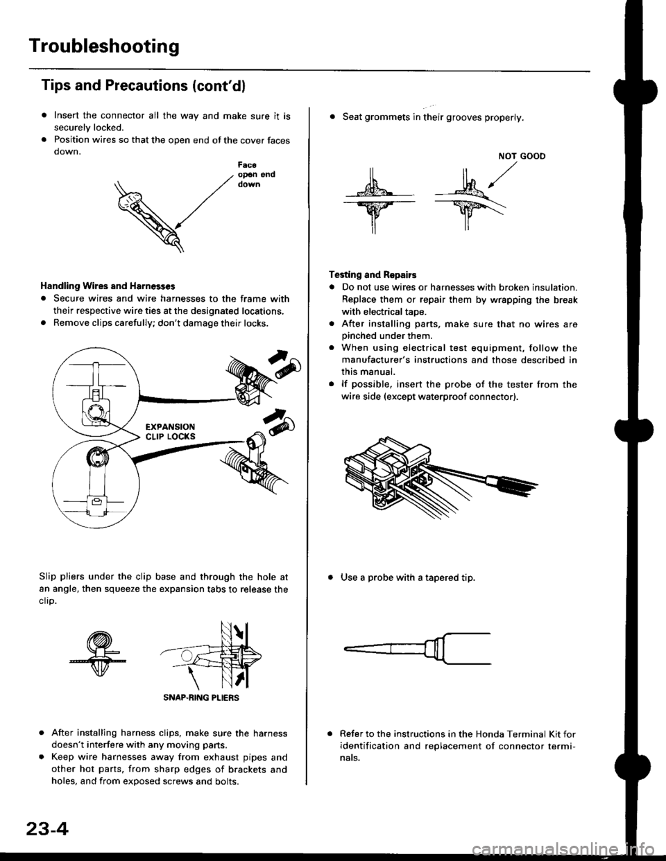
Troubleshooting
Tips and Precautions (cont'dl
Insert the connector all the way and make sure it is
securelv locked.
Position wires so that the open end of the cover faces
down.
After installing harness clips, make sure the harness
doesn't interfere with any moving pans.
Keep wire harnesses away from exhaust pipes and
other hot parts. from sharp edges of brackets and
holes, and from exDosed screws and bolts.
V
F6c6op€n end
Handling Wires and Harnosscs
. Secure wires and wire harnesses to the frame with
their respective wire ties at the designated locations,
. Remove clips carefully; don't damage their locks.
Slip pliers under the clip base and through the hole at
an angle, then squeeze the expansion tabs to release the
clrp.
SNAP-BING PLIERS
23-4
NOT GOOO
ll il,/
s*' -.1}8."/_Y--_Y5\
il ,,
Testing and Repairs
o Do not use wires or harnesses with broken insulation.
Replace them or repair them by wrspping the break
with electricaltaoe.
. After installing parts, make sure that no wires arepinched under them.. When using electrical test equipment, follow the
manufacturer's instructions and those described in
this manual.
. lf possible, insert the probe of the tester from the
wire side (except waterproof connector).
. Seat grommets in their grooves properly.
. Use a probe with a tapered tip.
Refer to the instructions in the Honda Terminal Kit for
identification and replacement of connector termi-
nats.
Page 1484 of 2189
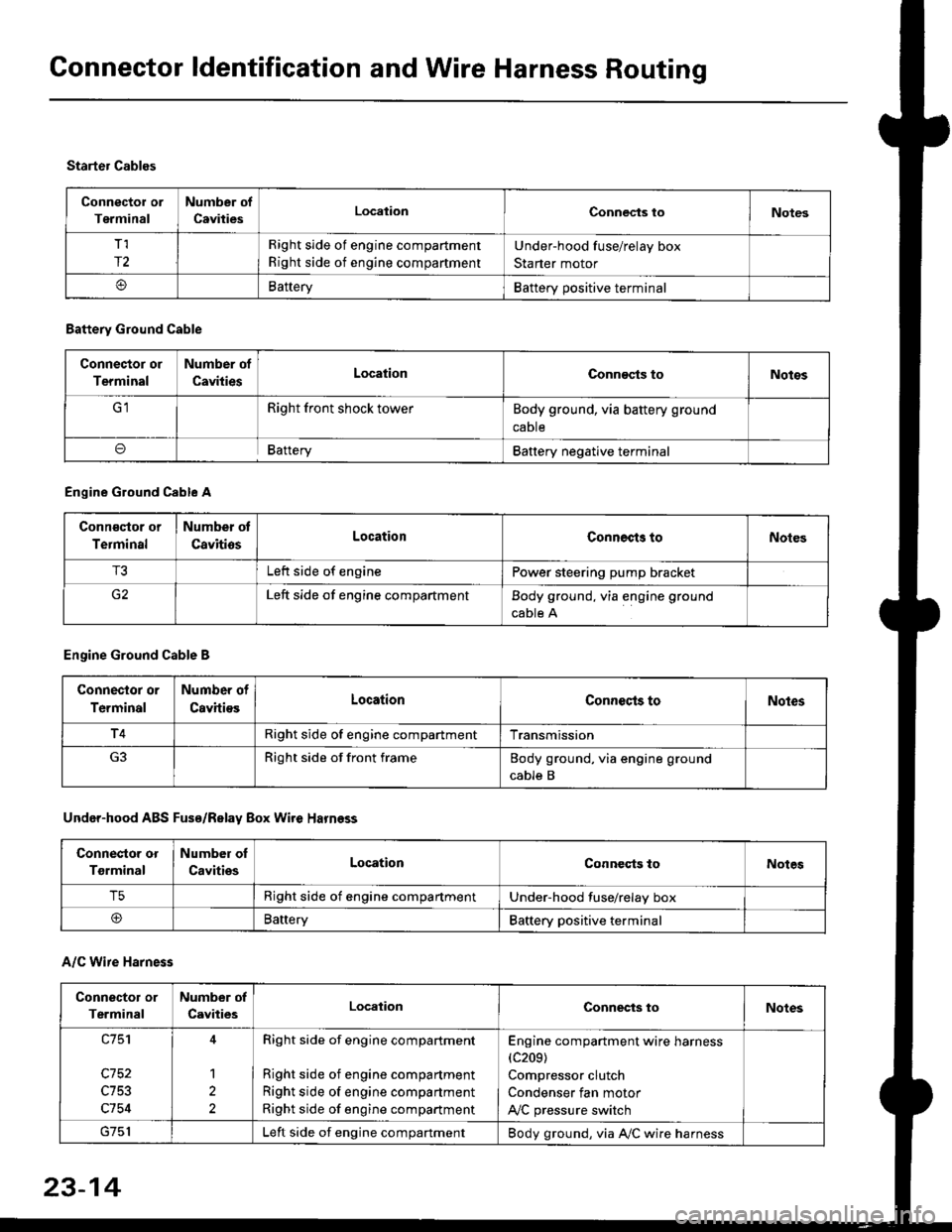
Connector ldentification and Wire Harness Routing
Connector or
Terminal
Number of
CavitiesLocalionConnec{s toNotes
T,I
r2
Right side of engine compartment
Right side of engine compartment
Under-hood fuse/relay box
Starter motor
BatteryBattery positive terminal
Starter Cables
A/C Wire Harness
Battery Ground Cable
Connector or
Terminal
Number of
CavitiesLocationConn€cts toNotos
Right front shock towerBody ground, via battery ground
caDte
oBafteryBattery negative terminal
Engine Ground Cable A
Conn€qtor or
Terminal
Number ot
CavitiosLocationConnects toNoles
T3Left side of enginePower steering pump bracket
G2Left side of engine compartmentBody ground, via engine ground
cable A
Engine Ground Cable B
Connector or
Terminal
Number of
CavitiesLocationConnecls toNoles
T4Right side of engine compartmentTransmission
Right side of front frameBody ground, via engine ground
cable B
Under-hood ABS Fusa/Relay Box Wire Harness
Connector or
Tgrminal
Number oI
CavitiesLocationConneqts toNotes
T5Right side of engine compartmentUnder-hood fuse/relay box
@BaneryBattery positive terminal
Connector or
Terminal
Number of
CavitiesLocationConnects toNotes
c753
c754
1
2
Right side of engine compartment
Right side of engine compartment
Right side of engine compartment
Right side of engine compartment
Engine compartment wire harness(c209)
Compressor clutch
Condenser fan motor
A,/C pressure switch
Left side of engine compartmentBody ground, via A,/C wire harness
23-14
Page 1827 of 2189
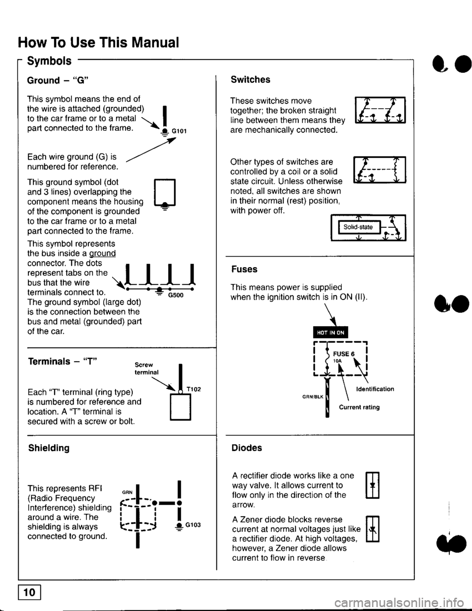
How To Use This Manual
Symbols
Ground - "G"
This symbol means the end ol
the wire is attached (grounded) Ito the car frame or to a metal I
part connected to the frame. \i oro,|
-t'
Each wire ground (G) it --/
numbered for reference.
oo
Switches
These switches move
together; the broken straight
line between them means the,
are mechanically connected.
Other types of switches are
controlled by a coil or a solid
state circuit. Unless otherwise
noted. all switches are shown
in their normal (rest) position,
with power off.
This ground symbol (dot
and 3 lines) overlapping the
component means the housing
of the component is grounded
to the car frame or to a metal
part connected to the frame.
This symbol represents
the bus inside a ground
connector. The dots I
i:l*,':1,'^:*,:"
;"
r"L I I I
terminals connect to.
The ground symbol (large dot)
is the connection between the
bus and metal (grounded) part
of the car.
Terminals - "T"
ffi
ffi
Solid-state
Fuses
This means power is supplied
when the ignition switch is in ON (ll).
Current rating
Diodes
A rectifier diode works like a one
way valve. lt allows current to
llow only in the direction of the
arrow.
A Zener diode blocks reverse
current at normal voltages just like
a rectifier diode. At high voltages.
however, a Zener diode allows
current to f low in reverse
oo
Each "T" lerminal (ring type)
is numbered for reference and
location. A "T" terminal is
secured with a screw or bolt.
Shielding
This represents RFI
(Radio Frequency
Interference) shielding
around a wire. The
shielding is always
connected to ground.
f--l;j-i",..
I
,,,,
T
Page 2141 of 2189
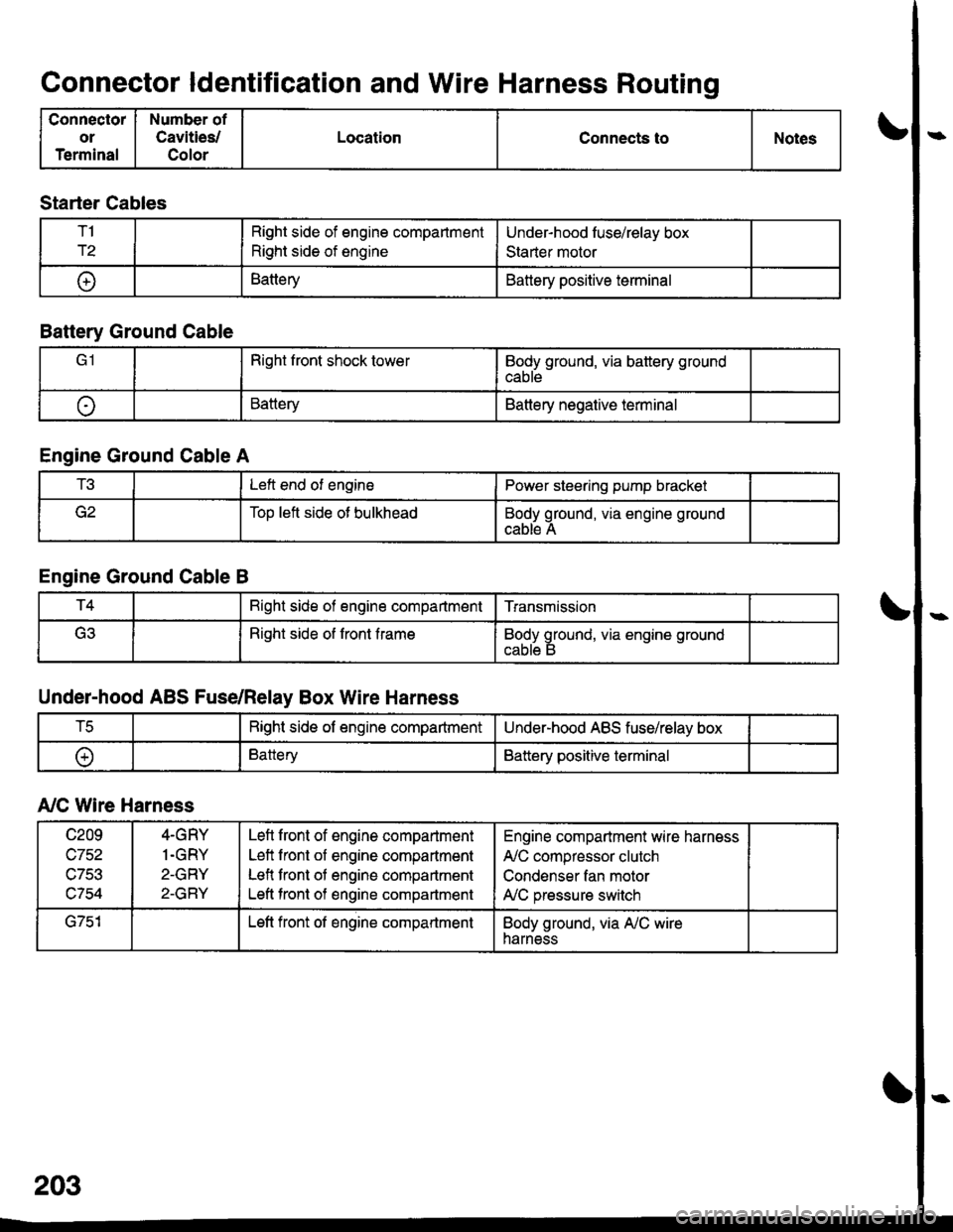
Connector ldentification and Wire Harness Routing
Connector
or
Terminal
Number of
Cavities/
Color
LocationConnects toNotes
Starter Cables
T1
r2
Right side of engine compartment
Right side of engine
Under-hood luse/relay box
Staner motor
t+lBatteryBattery positive terminal
Battery Ground Cable
Right front shock towerBody ground, via battery ground
cable
oBatteryBattery negative terminal
Engine Ground Cable A
t!tLeft end of enginePower steering pump bracket
Too left side ot bulkheadBody ground, via engine ground
cable A
Engine Ground Cable B
T4Bight side of engine compartmentTransmission
(ritRight side of front frameBody ground, via engine ground
Under-hood ABS Fuse/Relay Box Wire Harness
tcRight side of engine compartmentUnder-hood ABS fuse/relay box
oBatteryBattery positive terminal
A,/C Wire Harness
c209
wtJl/,\-7Ee
c754
4-GRY
1.GRY
2-GRY
2-GRY
Lefl front of engine compartment
Left front of engine compartment
Lefl front of engine compartment
Left tront of engine compartment
Engine compartment wire harness
A,/C compressor clutch
Condenser fan motor
A,/C pressure switch
G751Left front of engine compartmentBody ground, via A,/C wireharness