codes HONDA CIVIC 1998 6.G Owner's Manual
[x] Cancel search | Manufacturer: HONDA, Model Year: 1998, Model line: CIVIC, Model: HONDA CIVIC 1998 6.GPages: 2189, PDF Size: 69.39 MB
Page 1475 of 2189
t
Five-step Troubleshooting
2.
1.Verify The Complaint
Turn on all the components in the problem circuit to
verify the customer complaint. Note the symptoms.
Do not begin disassembly or testing until you have
narrowed down the problem area.
Analyze The Schematic
Look up the schematic for the problem circuit.
Determine how the circuit is supposed to work by
tracing the current paths from the power feed
through the circuit components to ground. lf several
circuits fail at the same time, the fuse or ground is a
likely cause.
Based on the symptoms and your understanding of
the circult operation, identify one or more possible
causes of the problem.
lsolate The Problem By Testing The Circuit
Make circuit tests to check the diagnosis you made
in step 2. Keep in mind that a logical, simple proce-
dure is the key to efficient troubleshooting. Test for
the most likely cause of failure first. Try to make
tests at points that are easily accessible.
Fix The Problem
Once the specific problem is identified, make the
repair. Be sure to use proper tools and safe proce-
dures.
Make Sure The Circuit Works
Turn on all components in the repaired circuit in all
modes to make sure you've fixed the entire prob-
lem. lf the problem was a blown fuse, be sure to
test all of the circuits on the fuse, Make sure no new
problems turn up and the original problem does not
recur.
3.
Wire Color Codes
The following abbreviations are used to identify wire
colors in the circuit schematics:
wHT ............................. White
YEL ............................... Yellow
BLK ............,.,...............81ack
BLU .............................. Blue
GRN .............................Green
RED .......................,...... Red
ORN ............................. Orange
PNK .............................. Pink
BRN .............................. Brown
GRY .............................. Gray
PUR .,.................,.,........ Purple
LT BLU ......................... Light Blue
LT GRN ........................ Light Green
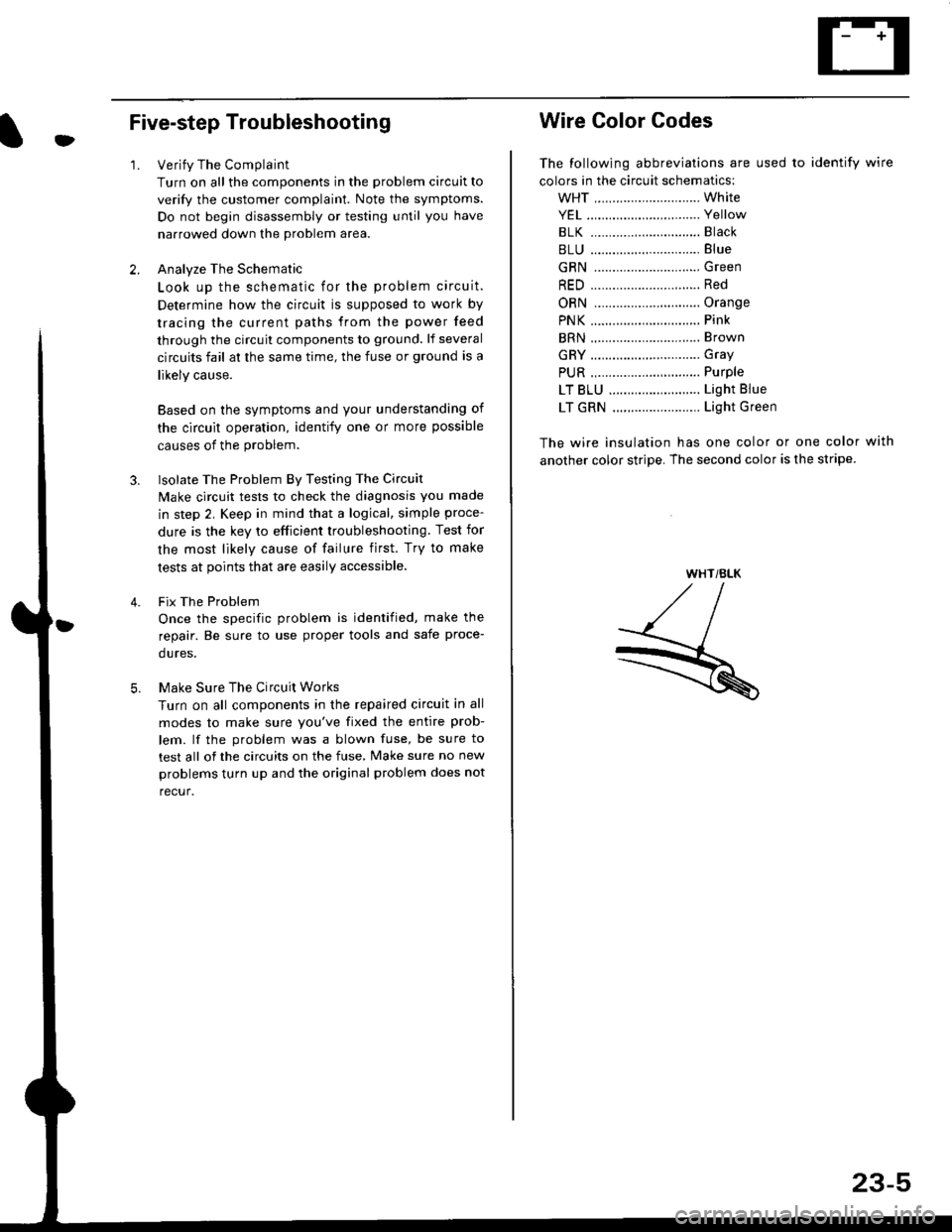
The wire insulation has one color or one color with
another color stripe. The second color is the stripe.
WHT/BLK
23-5
Page 1565 of 2189
-Starter Test
NOTE; The air temoerature must be between 59 and
100'F (15 and 38"C) before testing.
Recommended Procedure:
. Use a staner system tester.
. Connect and operate the equipment in accordance
with the manufacturer's instructions.
. Test and troubleshoot as described,
Alternate Procedurg:
. Use the following equipment:- Ammeter, 0 - 400 A
- Voltmeter, 0 - 20 V (accurate within 0.1 volt)
- Tachometer, 0 - 1,200 rpm
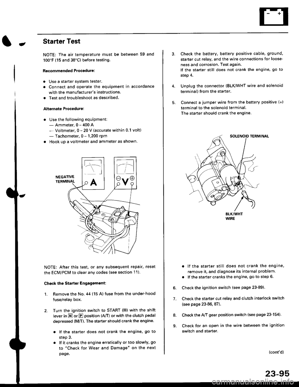
. Hook up a voltmeter and ammeter as shown.
NEGATIVETERMINAL
NOTE: After this test, or any subsequent repair. reset
the ECM/PCM to clear any codes (see section l1)
Check the Start€r Engagemont:
1. Remove the No. 44 (15 A) fuse from the under-hood
fuse/relay box,
2. Turn the ignition switch to START (llll with the shift
lever in E or E position (rVT) or with the clutch pedal
depressed {M/T). The starter should crank the engine.
. lf the starter does not crank the engine, go to
step 3.
. lf itcranksthe engineerraticallyortooslowly, go
to "Check for Wear and Damage" on the next
page.
Check the battery. battery positive cable, ground,
starter cut relay, and the wire connections for loose-
ness and corrosion, Test again.
lf the starter still does not crank the engine, go to
step 4,
Unplug the connector (BLK,/WHT wire and solenoid
terminal) from the starter,
Connect a jumper wire from the battery positive (+)
terminal to the solenoid terminal.
The starter should crank the engine.
. lf the starter still does not crank the engine,
remove it, and diagnose its internal problem
. lf the startercranksthe engine, goto step 6.
Check the ignition switch (see page 23-891.
Check the starter cut relay and clutch interlock switch
(see page 23-86,87).
Check the A/f gear position switch (see page 23-154).
Check for an open in the wire between the ignition
switch and starter.
7.
(cont'd)
23-95
9.
Page 1737 of 2189
)
Transmitter Programming ('96 - 98 models)
Storing Transmitter Codes
. The codes of up to four transmitters can be stored in the control unit. {lf a {ifth code is stored, the code which was
stored tirst will be erased.)
. When the system enters the registration mode, all previously slored codes will be erased.
. The system leaves the registration mode and returns to the normal mode if you
- turn the valet swirch OFF, or
- turn the ignition switch OFF, or
- do not press the transmitter button for more than 10 seconds
Procedure:
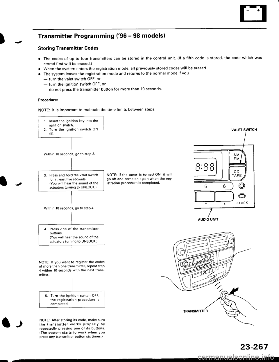
NOTE: lt is important to maintain the time limits between steps
VALET SWITCH
NOTE: lf the tuner is turned ON, it willgo off and come on again when the reg-
istration procedure is completed-
l-l
NOTE: lf you want to register the codesof more than one transmitter, repeat step4 within 10 seconds with the next trans'mitter.
NOTE: After storing its code, make sure
the transmitter works properly bYrepeatedly pressing one ot its buttons.(The system starts to work when Youpress any transmitter button six times-)
TRANSMTITTER
23-267
--
Insert the ignition key into the
ignition swatch.Turn the ignit;on switch ON
flr).
Within 10 seconds, go to steP 3.
3. Press and hold the valet switchfor at least tive seconds.(You will hear the sound of theactuators turnang to UNLOCK.)
Within 10 seconds. go to step 4.
4. Press one of the transmitterbuttons,(You will hear the sound of theactuators turning to UNLOCK.i
AUDIO UNIT
Page 1738 of 2189
Power Door Locks
Transmitter Programming ('99 - 00 modelsl
Storing transmitter codes;
The codes of up to three transmitters can be read into
the keyless receiver unit memory. (lf a fourth code is
stored, the code which was input first will be erased.)
NOTE: lt is important to maintain the time limits
between the steps.
'1. Turn the ignition switch ON (ll).
2. Within 1 to 4 sec., push the transmitter lock or unlock
button with the transmitter aimed at the vehicle.
3. Within I to 4 sec., turn the ignition switch OFF.
4. Within 1 to 4 sec., turn the ignition switch ON 1ll).
5. Within 1 to 4 sec., push the transmitter lock or
unlock button with the transmitter aimed at the
vehicle.
6. Within 1 to 4 sec., turn the ignition switch OFF.
7. Within 4 sec., turn the ignition switch ON (ll).
8. Within 1 to 4 sec., push the transmitter lock or
unlock button with the transmitter aimed at the
vehicle.
9.Within 1 to 4 sec., turn the ignition switch OFF.
Within 4 sec., turn the ignition switch ON (ll).
Within '1 to 4 sec., push the transmitter lock or
unlock button with the transmitter aimed at the
vehicle.
Confirm you can hear the sound of the door lock
acIuarors.
Within 8 sec., aim the transmitters (up to three)
whose codes you want to store at the receiver, and
press the transmitter lock or unlock buttons.
Contirm that you can hear the sound of the door
lock actuators after each transmitter code is stored.
Turn the ignition switch OFF, and pull out the key.
Confirm proper operation with the new code(s).
'10.
11.
12.
14.
23-268
Page 1857 of 2189
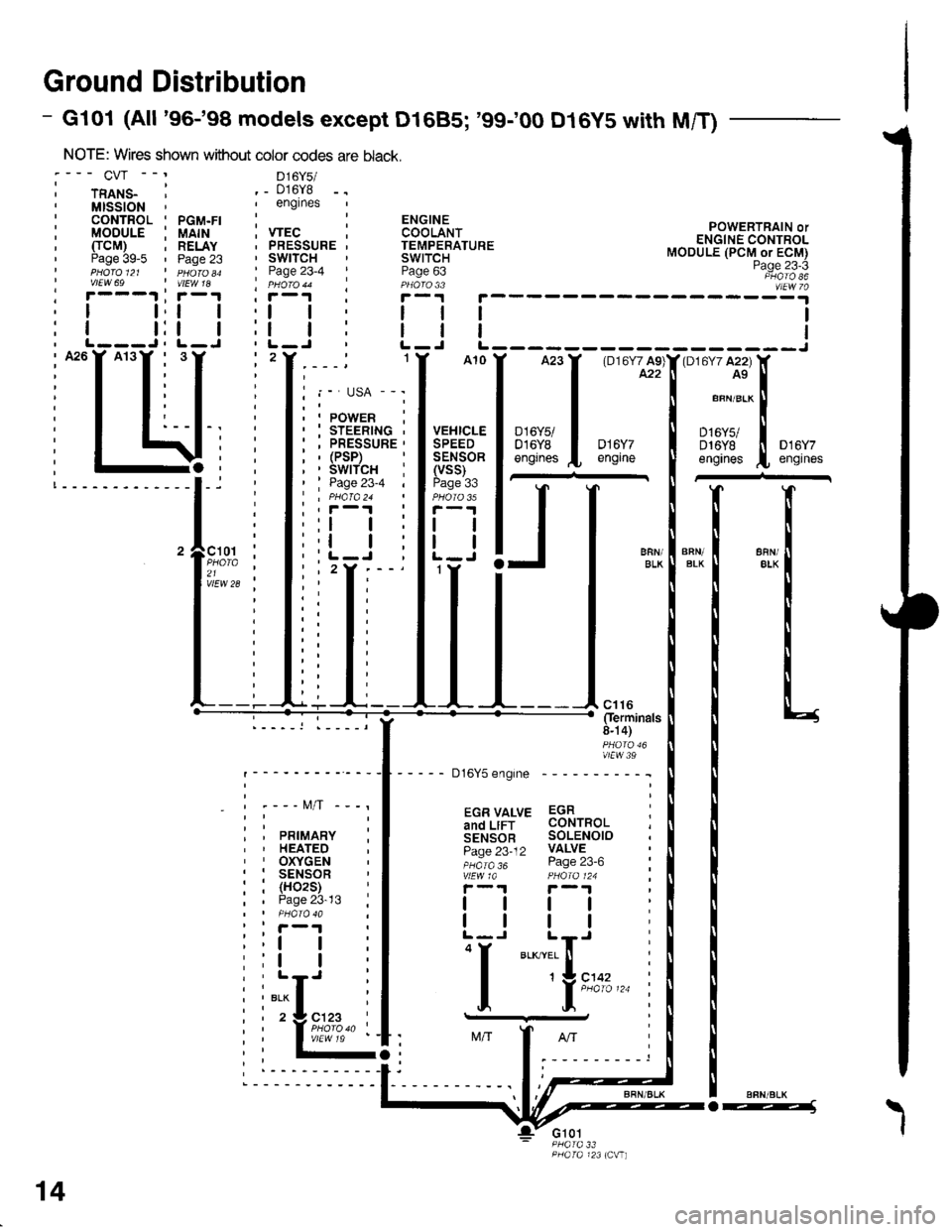
Ground Distribution
- Gl01 (All '96-'98 models except D1685; '99100 D16y5 with M/T)
NOTE: Wires shown without color codes
:--- CVr --' D16y5/
i rnlts_ ' ._ 016y8,MISSION',englnes
: CONTROL ' PGM.FI :: MODULE i UAIH ; VTEC, TTCM) ; RELAY . PRESSURE' Paae 39-5 ' Paoe 23 ' SWITCHI pHdro et ' n 6roao ' Page 23-4I vtEw 69 | vtEw 1a ' pHoro 44' r---.t ' r-1 I i-r
POWERTRAIN orENGINE CONTROLMODULE (PCM or ECM)Page 23-3PHATO 86vlEw 7a; r---1 ;r-1 , r, I t,t | ,l
: I t:t | :l, L---J, L-J ' L-, A26Y A13Y , 3,2
i T T: I I
I I, I t,,-I T T: T i
: I t:--I-. :
i I \li:; -4, ;!-------------l-i '
'lF;% :21 ,vlEw 28 ;
_ - t\4/T -
PRIMARYHEATEDOXYGENSENSOR(H02S)Page 23-13
ll
tl
"i[",..
14
o---1\
I
Page 1859 of 2189
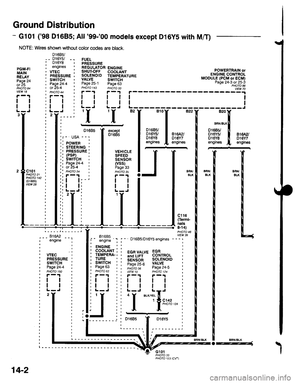
Ground Distribution
- Gl01 ('98 Dl685;All '99-'00 models except D16YS with M/T)
NOTE: Wires shown without color codes are black.
01685/_ D16Y5/ -.016Y8engrnes
.__-;,#'-_,--', engrne ;
, wEc: PRESSURE '
, swtTcH :I Page24-4 iI PHOTO 150: r -'l
:t | :
:l | :,L-J.
FUELPRESSUREREGULATOR ENGINESHUT.OFF COOLANTSOLENOID TEMPERATUREVALVE SWTTCHPage 25-1 Page 63PHOIO 143 PHOTA 33r-1F-.|
llll
lltlL-J L-J
POWERTRAIN olENGINE CONTROLMODULE (PCM or ECM)Page 24-3 ot 25-3PHOTO 86
----:y4
tl
tl
PGi,|.FIMAINRELAYPage 24ol 25
vlEw 18
tl
tl
3Y'I'I
excaptD1685
VEHICLESPEEDSENSOR(vss)Page 336FN/ELKERll/EIKcl01PHOTO 21PHOTO 142(o1685)vtEw 28
ct16Cferml-nals8n 4)
FltaFt( vttw 39t- .''iiti ' " D1685/D16Y5 engrnes ---'
t2
. ENGINE : :
i 933'?il-; i 5"T,Yf,*' 33i,"o, i
i lgfft" i I S.ir1".l^ soL€NorD :' Pase 63 : : ;;;;; - pase 24.i :' PHOTO 63 | | VtEWlO pHOIa124 ;, r-1 | , F-.t r-.r
:l | ;:l | ! | :;t | :,t | | | ;
j,f
ii T.__.,|,,,,,.
j
--
----- --l i otoas I Dr6y5 :
:------.1.--------.
14-2
o-----J
Page 1861 of 2189
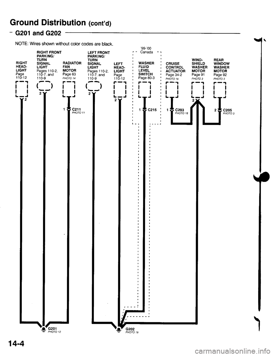
Ground Distributiofl (cont'd)
- G201 andG202
NOTE: Wires shown wrthout color codes are black.
RIGHTHEAD.LIGHTPage110-12
tl
tl
110-9
{}tl
tl
LEFT FRONTPARKING/TURNSIGNALLIGHTPages 110-2,1 10-7, and110-9
()
WIND.SHIELDWASHERMOTORPage 91PHOTA 3
ll
tl
REARwtNDowWASHERMOTORPage 92
tl
tt
c205
RIGHT FRONTPARKING/TURNStcNAL RADIATORLIGHT FANPaoes 110-2, MOTOR11d-7, and Page 63
'99-'�00
.- Canada -l
i wnsxen i cnurse, FLUID ; CONTROL' LEVEL . ACTUATOR' SWITCH I paoe 34-2; Page 80-3 i eu6ro re'f-1 ' f-1
2Y2
c211
14-4
I'G201'Lv G2o2
Page 1862 of 2189
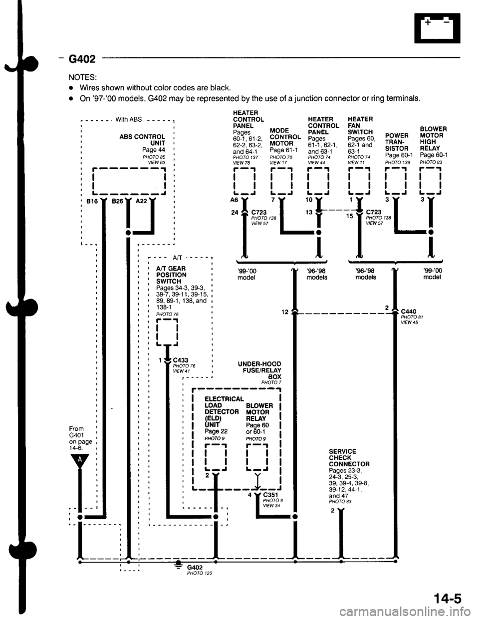
- G402
NOTES:
. Wires shown without color codes are black.
. On '97-'00 models, G402 may be represented by the use of a junction connector or ring terminals.
with ABS - - - - - I
. ABS CONTROL I' ultt '
HEATERCONTROL HEATER HEATER
iili, BB-'fi",. Eiff* 5fi::g PowER i,8;g'"'
;;; ;;; MoroR ;il--"'. ;;1-;; rRAN- H|GH
!if,6f1- ease ot-t Ino b5-.t ' fi i *- slsroR FELAY- ,pHaTa t3z pHoro 70 photoT. iioro ^ Page 60-1 Page 60-1vtEw 76 vlEW 17 V|EW 44 V|EW11 PHOTO139 PHOTO 83
r-1r-.!r-1r-1r-.|r-1
| | | | | | rl I lll
| | | | | | I ll ll IL-J L-J L-J L.J L-J L-J
Page 44PHOTO 85vtEW 63
I
I------J
I""IJ
Ifnn*"1 r'[
1"""LI'--- A/l ---_r
i , m cean; I POStflON, : swrrcH :' , Pages 34-3, 39-3, :' | 39-7,39-11,39-15,;: ' 89, 89-1, 138, and ,
; : 138-1| | PHO|OIA :' , F-'t .
'99-'00
mooel
'96-'�98
moo€ts
'9G'S
mod6ls
'99-'00
modol
a
12c440
vtEw 45
FromG401on page14-6.
v
l-
SERVICECHECKCONNECTORPages 23-3,24-3,25-3,39, 39-4, 39-8,39-12,44-1,afid 47
c402
I
I
3 cass
l;l:,12,
li
rc i UNDER-HOOD, FUSE/RELAYBOXPHAfa 7
I elecrRrca- |I LOAD BLOWER I: DETECTOR MOTOR iI (ELD) RELAY II UNlf Paoe 60 |
a W.': :;ffil iI r-r F-'r I
tt | | | |
tr | | | |I L-J L-J I
i 'r Y iL--+---J--J
I
'I&%,14.,I
14-5
Page 1863 of 2189
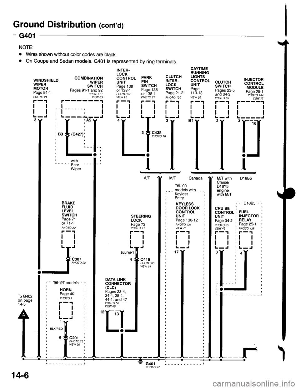
Ground Distributioh (conrd)
)
- G401
NOTE:
To G402on page14-5.
WINOSHIELOWIPERMOTORPage 91-1
DAYTIMERUNNINGLIGHTS
99.!rRoL cLUrcHuNr I swtTcH:?99^ Pases 23-5and 34-3vtEw 66 PHA|A 55
I
I
INJECTORCONTROLMODULEPage 25-1
I
I
3
. Wires shown without color codes are black.
o On Coupe and Sedan models, G401 is represented by ring terminals.
tl
tl
INTER.LOCK6611p99 PARKUN|T PINpaoe j38 SWITCHor ige_t Page 138PHoro6s of 138-1vtEw 26 PHOfO /7r-1 r-'t
tttl
CLUTCHINTER-LOCKSWITCHPage 21-2
ll
ll
ttl
rll
I
Itttl
'Ll;
I
n
t
M/T with 01685Cruise/D16Y5enginewith M/T
BRAKEFLUIDLEVELswtTcHPage 71ot 71-1
tl
tl
DOOR LOCK .CONTROLSTEERINGLOCKPage /3
tl
tl
UNITPage 130-12 ;
ttl
tt:
models
RNte 40
I
I
(
I
I czor
l'i1l?,
'97 mo
HORNPage 4
I
I
NFnl
s 9c.Plv'
BLK/RED
t
IJ;--
',f-l
DATA LINKCONNECTOR(DLC)Pages 23-4,24-4,25 4,44-1, and 47
30
14-6
G401
Page 1865 of 2189
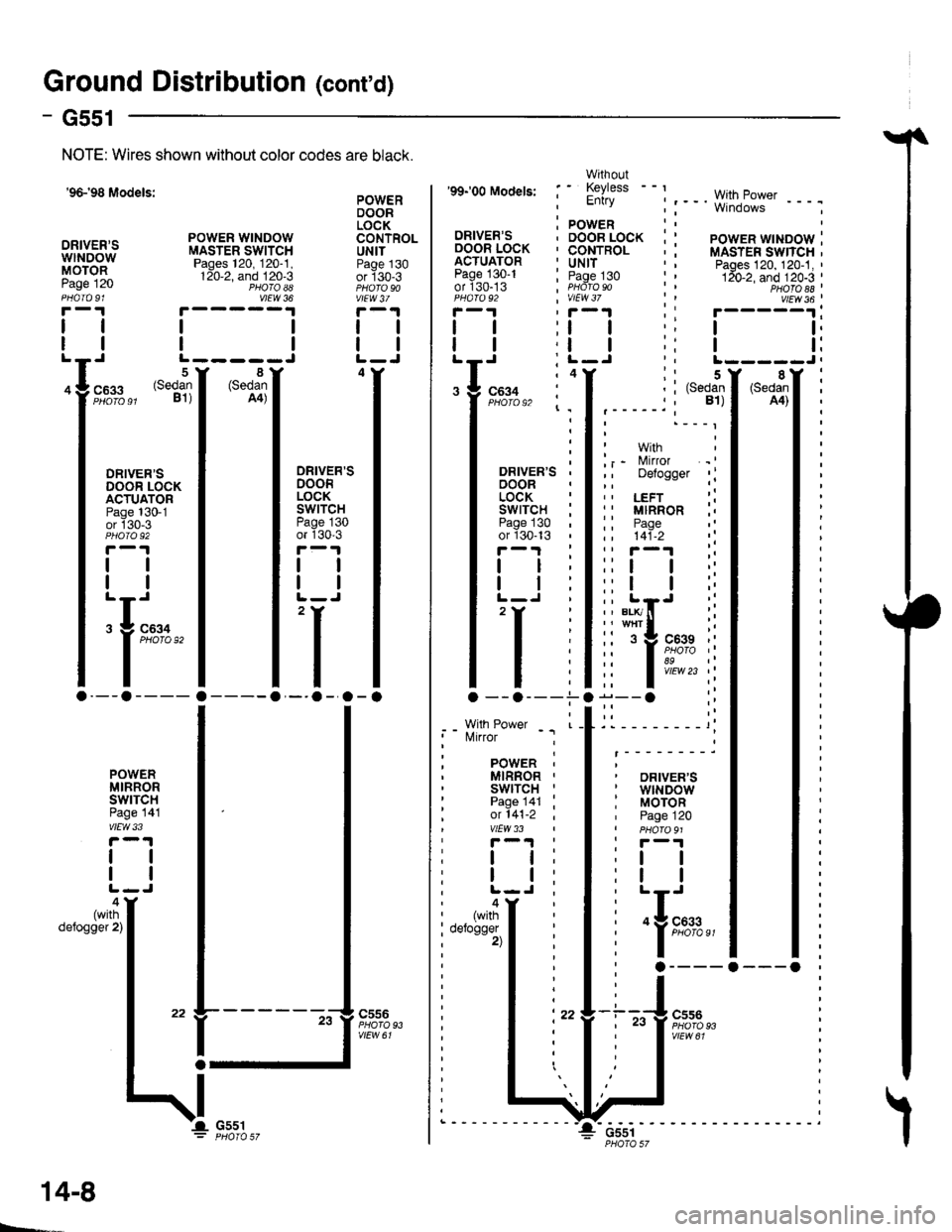
Ground Distribution (cont'd)
1
- G551
Page
I
I
'96-'98 Models:
DRIVER'SwtNDowMOTOR
NOTE: Wires shown without color codes are black.
4
12091
I
I
c633
oRrvER'sDOOR LOCKACTUATORPage 130-1or 130-3
tl
tl
:f ;'*"
.--a ----
sl)
POWER WINDOWMASTER SWITCHPages 120, 120-1,120-2, and 120-3PHO|O AAvlEW 36
tl
tlL-----J
POWERDOORLOCKCONTROLUNITPage 130or 130-3
vlEW3/
tl
tl
4
c556
vtEw 61
8(SedanA4)
DRIVER'SDOORLOCKswrTcHPage 130or 130-3
tl
tl
,I
'-.o -.o -
POWERMIRRORswrTcHPage 141vlEw 33
ll
tl
4(withdefogger 2)
G55t
14-8