front engine HONDA CIVIC 1998 6.G Owner's Manual
[x] Cancel search | Manufacturer: HONDA, Model Year: 1998, Model line: CIVIC, Model: HONDA CIVIC 1998 6.GPages: 2189, PDF Size: 69.39 MB
Page 682 of 2189
Description
(cont'dl
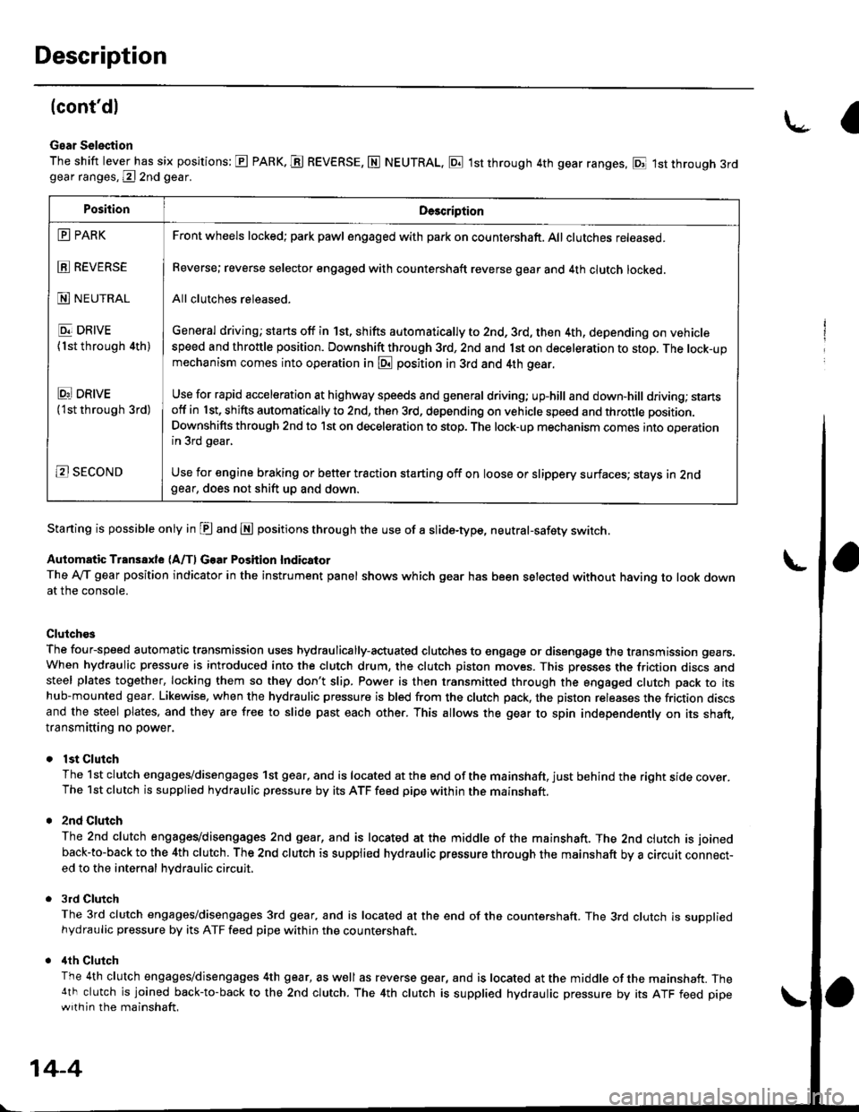
Gear Selection
The shift lever has six positions: E PARK. E REVERSE, N NEUTRAL, E 1st through 4th gear ranges, E 1st through 3rdgear ranges, @ 2nd gear.
Starting is possible only in E and E positions through the use of a slide-type, neutral-safety switch.
Automatic Transaxle (A/f, Gear Position Indicator
The Ay'T gear position indicator in the instrument panel shows which gear has been selected without having to look downat the console.
Clutch€s
The four-speed automatic transmission uses hydraulically-actuated clutches to engage or disengage the transmission gears.When hydraulic pressure is introduced into the clutch drum, the clutch piston moves. This presses the friction discs andsteel plates together, locking them so they don't slip. Power is then transmitted through the engaged clutch pack to itshub-mounted gear. Likewise, when the hydraulic pressure is bled from the clutch pack, the piston releases the friction discsand the steel plates, and they are free to slide past each other. This allows the gear to spin independently on its shaft,transmitting no power.
lst Clutch
The 1st clutch engages/disengages 1st gear, and is located at the end of the mainshaft, just behind the right sroe cover.The 1st clutch is supplied hydraulic pressure by its ATF feed pipe within the mainshaft.
2nd Clulch
The 2nd clutch engagegdisengages 2nd gear, and is located at the middle of the mainshaft. The 2nd clutch is joined
back-to-back to the 4th clutch. The 2nd clutch is supplied hydraulic pressure through the mainshaft by a circutr connect-ed to the internal hvdraulic circuit,
3rd Clutch
The 3rd clutch engages/disengages 3rd gear, and is located at the end of the countershaft. The 3rd clutch is suooliedhydraulic pressure by its ATF feed pipe within the countershaft.
ilth Clutch
The 4th clutch engages/disengages 4th gear, as well as reverse gear, and is located at the middle of the mainshaft. The4th clutch is joined back-to-back to the 2nd clutch. The 4th clutch is supplied hydraulic pressure by its ATF feed pipewith in the mainshaft.
\-a
PositionDe3cription
E PARK
E REVERSE
N NEUTRAL
E DRIVE
{1st through 4th)
Ei DRtvE('lst through 3rd)
B SECOND
Front wheels locked; park pawl engaged with pa* on countershaft. All clutches released.
Reverse; reverse selector engaged with countershaft reverse gear and 4th clutch locked.
All clutches released.
General driving; starts off in 1st, shifts automatically to 2nd, 3rd, then 4th, depending on vehiclespeed and throttle position. Downshift through 3rd, 2nd and 1st on deceleration to stop. The lock-upmechanism comes into operation in @ position in 3rd and 4th gear.
Use for rapid acceleration at highway speeds and general driving; up-hill and down,hill dfiving; stansotf in 1st, shifts automatically to 2nd, then 3rd, depending on vehicle speed and throttle position.
Downshifts through 2nd to lst on deceleration to stop. The lock-up mechanism comes into operationin 3rd gear,
Use for engine braking or better traction starting off on loose or slippery surfaces; stays in 2ndgear, does not shift up and down.
14-4
Page 794 of 2189
Stall Speed
Test
CAUTION:
. To prev€nt transmission damage, do not t6st stall speed for more than ro sgconds at a time.. Do not shift the levor while raising the engine speed.. Bo sule lo remove the pressure gauge betoro testing stall speed.
'1. Engage the parking brake, and block the front wheels.
2. Connect a tachometer to the engine, and start the engine.
3. Make sure the Ay'C switch is OFF.
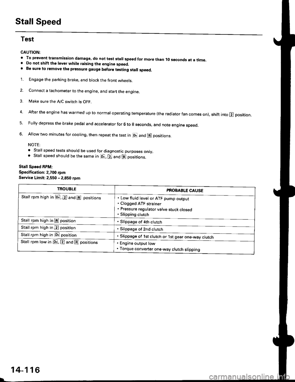
4. After the engine has warmed up to normal operating temperature (the radiator fan comes on). shift into E position.
5. Fully depress the brake pedal and accelerator for 6 to g seconds, and note engine speed.
6. Allow two minutes for cooling, then repeat the test in @ and @ positions.
NOTE:
. Stall speed tests should be used for diagnostic purposes only,. Stall speed should be the same in o., E and E positions.
Stall Spsed RPM:
Specification: 2.700 rpm
Service Limit: 2,550 - 2,850 rDm
TROUBLEPROBABLE CAUSE
. Low fluid level or ATF pump outDur. Clogged ATF strainer. Pressure regulator valve sluck closeo. Slipping clutch
. Slippage of 4th ctutch
. Slippage of 2nd clutch
. Slippage of lst clut"tr or. t"t g""io*-*"y "lut"h
Stall rpm high in D., E and E positions
Stall rpm high in El position
Stall rpm high in E posirion
Stall rpm high in E position
Stall rpm low in LDa . El and E positrons. Engine output low. Torque converter one-way clutch slipping
14-116
Page 795 of 2189
Fluid Level
Ghecking
NOTE: Keep all foreign particles out of the transmis-
sron.
1.Warm up the engine to normal operating tempera-
ture (the radiator fan comes on)
Park the vehicle on the level ground, then turn off
the engrne.
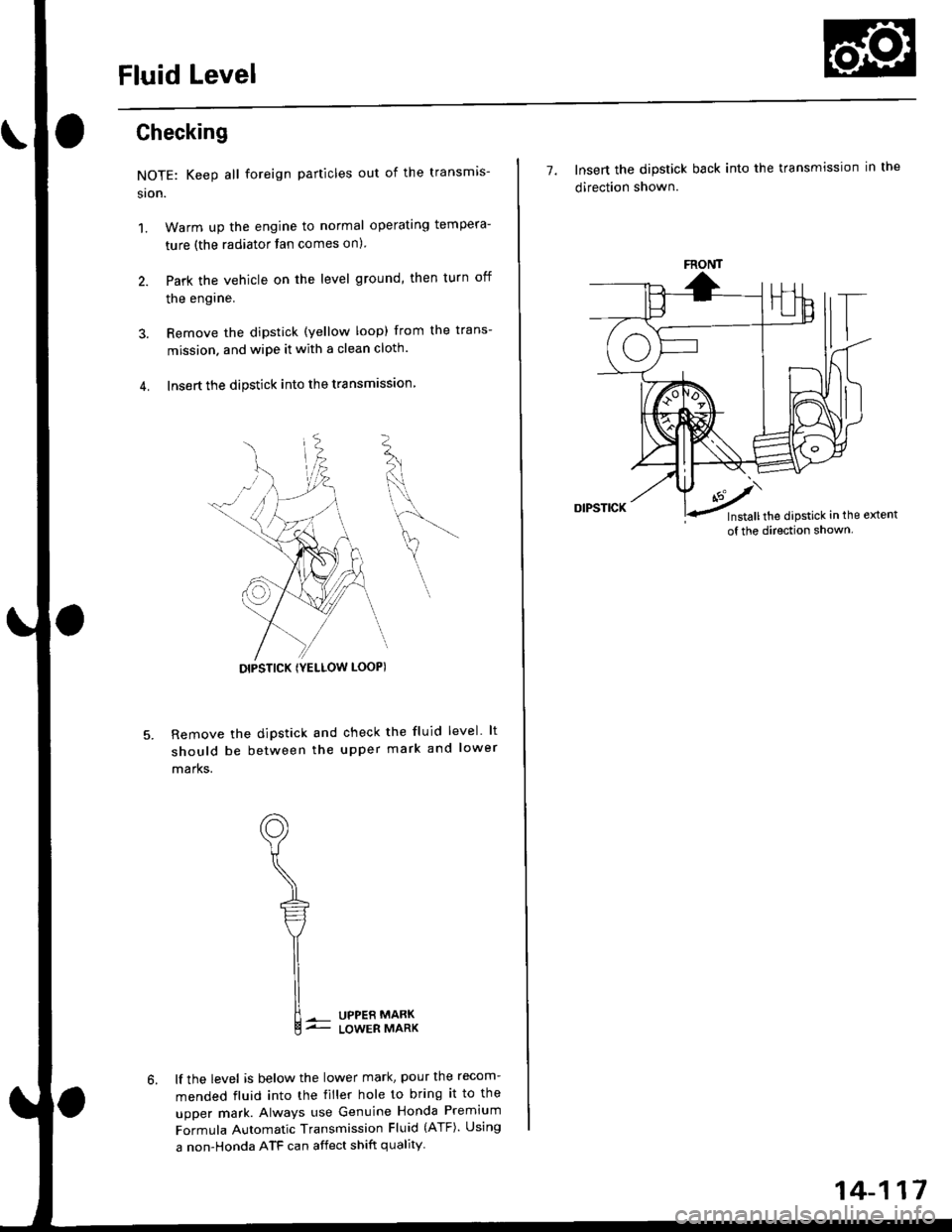
Remove the dipstick (yellow loop) from the trans-
mission. and wipe it with a clean cloth.
Insert the dipstick into the transmrssron
Remove the dipstick and check the fluid level lt
should be between the upper mark and lower
marks.
UPPER MABKLOWER MARK
lf the level is below the lower mark, pour the recom-
mended fluid into the tiller hole to bring it to the
upper mark. Always use Genuine Honda Premium
Formula Automatic Transmission Fluid (ATF). Using
a non-Honda ATF can affect shift quality
K
L
DIPSTICK IYELLOW LOOPI
7. Insert the dipstick back into the transmission in the
direction shown.
FRONT
Installthe dipstick in the extent
of the direction shown.
14-117
Page 797 of 2189
Pressure Testing
@I While testing, be caroful of th€ rotating front wheels.
. Make sure lifts, iacks, and satoty stands are placod properly (see section 1)'
CAUTION:
. Beforo iesting, be sure the transmission fluid is tilled to tho proper level'
. Warm up tho engine before testing'
1. Raise the vehicle (see section 1).
2. Warm up the engine, then stop the engine and connect a tachometer'
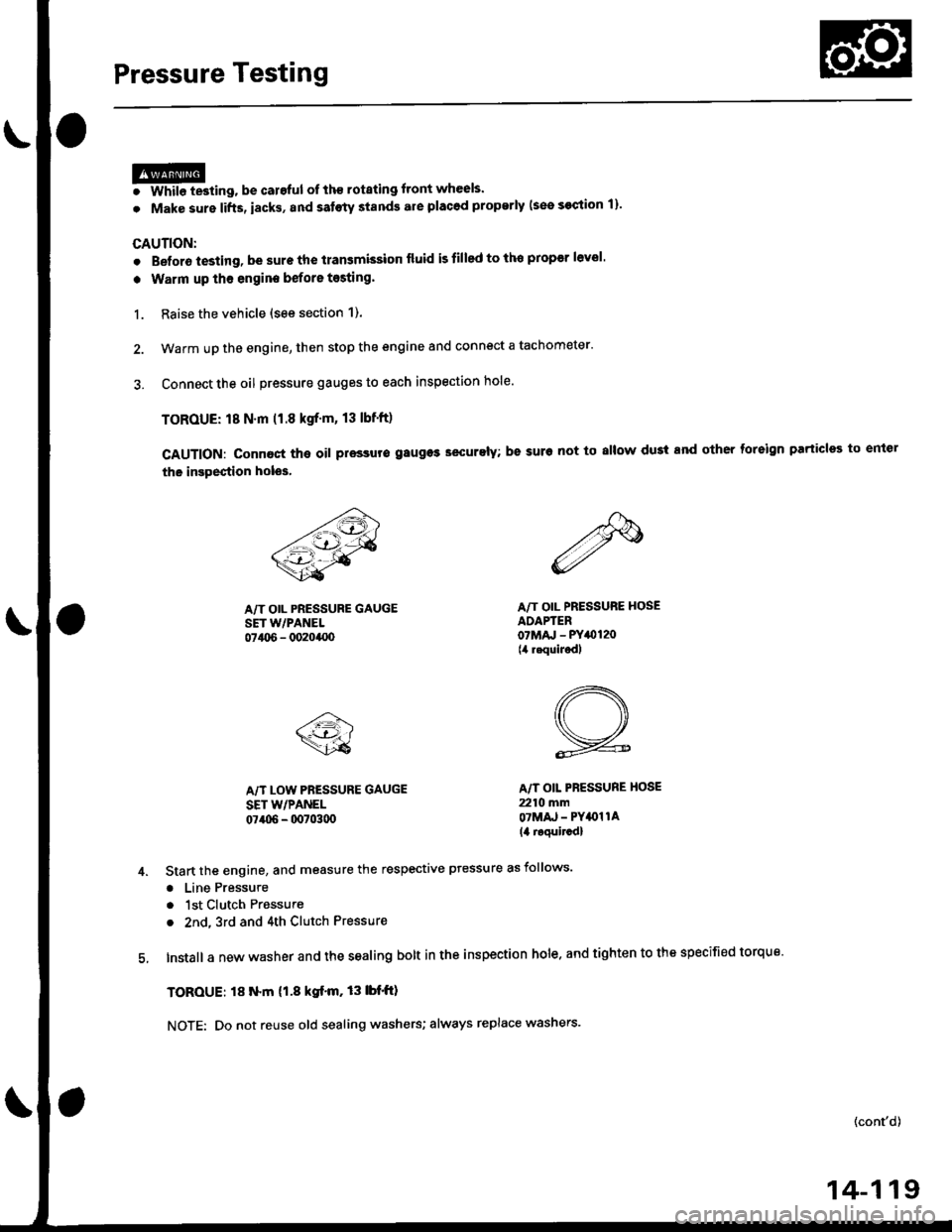
3. Connect the oil pressure gauges to each inspection hole.
TOROUE: 18 N.m (1.8 kgf'm, 13 lbnft)
cAUTloN: connact the oil pressuro gauges securely; be suro not to allow dust and other foreign Parlicles to entel
the inspestion holos'
A/T OIL PRESSURE GAUGESET w/PANEL07t06 - 0020400
A/T LOW PRESSURE GAUGE
SET WPANEL07406 - 0070300
A/T OIL PRESSURE HOSEADAPTER07Mru - PY0120(4 requiJedl
A/T OIL PBESSURE HOSE
2210 mmOTMAJ - PY4{)llA
14 roquircdl
Start the engine, and measure the respective ptessure as follows'
a Line Pressure
. 1st Clutch Pressure
. 2nd,3rd and 4th Clutch Pressure
Install a new washer and the sealing bolt in the inspection hole. and tighten to the specified torque'
TOROUE: l8 N.m (1.8 kgf'm,13lbf'ft)
NOTE: Do not reuse old sealing washers; always replace washers'
(cont'd)
14-119
Page 802 of 2189
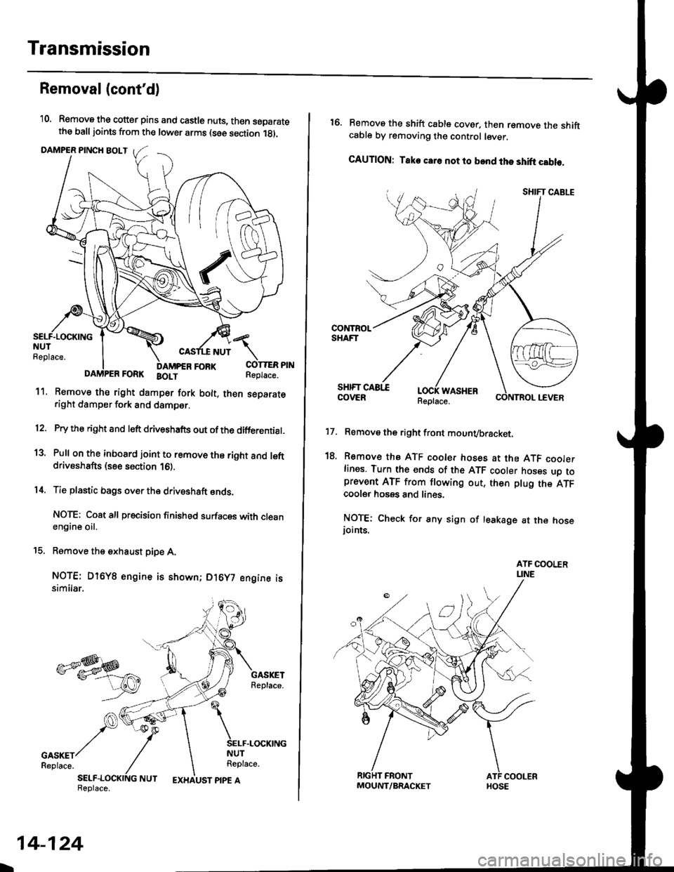
Transmission
Removal(cont'd)
'10. Remove the cotter pins and castle nuts, th€n separatethe balljoints from the lower arms (see section 1gl.
DAMPER PINCH BOLT
NUT
FORI(FORK BOLT
11. Remove the right damper fork bolt. th€nright damper fork and dampor.
COTTER PINReplace.
separate
12.
1a
14.
Pry the right and left driveshafts out ofthe differential.
Pull on the inboard joint to remove the right and leftdrivsshafts (see section 16).
Tie plastic bags over the driveshaft onds.
NOTE: Coat all precision finished surfaces with cleanengine oil.
Remove the exhaust pipe A,
NOTE: Dl6YB engine is shown; D16y7 engine issimilar.
t9.
SELF-LOCKING NUTReplace.
L
14-124
EXHAUST PIPE AMOUNT/BRACKET
17.
18.
16. Remove the shift cable cover. then remove the shiftcable by removing the control lever,
CAUTION: Take car6 not to bond the shift cable.
Remove the right front mounvbracket.
Remove the ATF cooler hoses at the ATF coolerlines. Tufn the ends of the ATF cooler hoses uo toprevent ATF from flowing out, then plug the ATFcooler hosgs and lines.
NOTE: Check for any sign of leakage at the hoseioints.
WASHER
Page 862 of 2189
Transmission
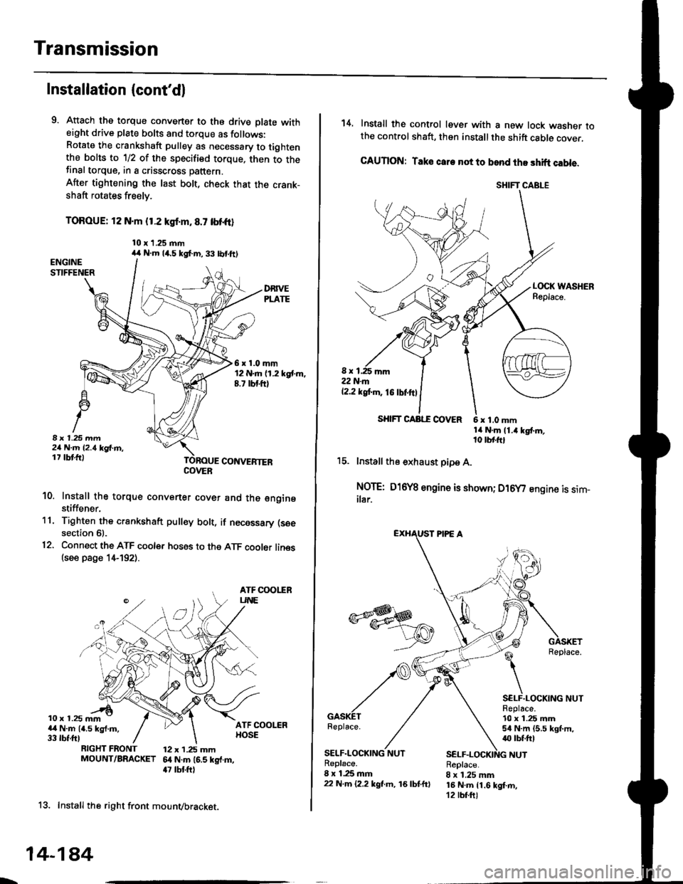
Installation (cont'dl
9. Attach the torque converter to the drive plate witheight drive plate bolts and torque as follows:Rotate the crankshaft pulley as necessary to tightenthe bolts to 1/2 of the specified torque. then to thefinal torque, in a crisscross pattern.
After tightening the last bolt, check that the crank-shaft rotates freely.
TOROUE: 12 N.m {1.2 kgl.m, 8.7 tbt{r}
10 x 1.25 mm
6x1.0mm12 N.m (1.2 kgt m,8.7 rbt ft)
I 1.25 mm2/t N.m {2.4 kg{.m,17 tbt ftlCONVERTEB
10. Install the torque convener cover and the €nginestiffener.'11. Tighten the crsnkshaft pull€y bolt, if necessary (see
section 61.
12. Connect the ATF cooler hoses to the ATF cooler lines(see page 1,t192).
ATF COOIIRUNE
10 x 1.25 mma,l N.m {4.5 kgl.m,33 rbt.fttRIGHT FRONT 12 x 1.25 mmMOUNT/BRACKET 6.t N.m (6.5 kg{.m,47 tbt ftl
13. Install the right front mounvbracket.
4,r N.m 14.5 kgf.m,33 lbtft)
COVER
L,
14-1A4
SHIFT CABLE
SHIFT CAAE COVER
14. Install the control lever with a new lock washer tothe control shaft, then install the shift cable cover.
CAUION: Taks care not to bend the shift cable.
L(rcK WASHERReplace.
8 x 1,25 r'|m22N-m12.2 tgt m. 16lbnftl
x 1.0 mmtit N.m 11.4 kgt m,10 tbr,ft,
15. lnstall the exhaust pipe A.
NOTE: D16Y8 engine is shown; D16y/ engine is sim_ilar.
Replace.
GASKETReplace.
SELF.LOCKING NUTReplace.10 x 1.25 mm54 N.m (5.5 lgf.m,40 tbt ftl
NUTSELF.LOCKING NUTReplace.8 x 1.25 mm22 N.m {2.2 kgl.m, 16lbtfrl
Replace.8 x 1.25 mm16 N.m {1.6 kgI.m,12 tbf.ft)
Page 864 of 2189
Transmission
Installation {cont'd)
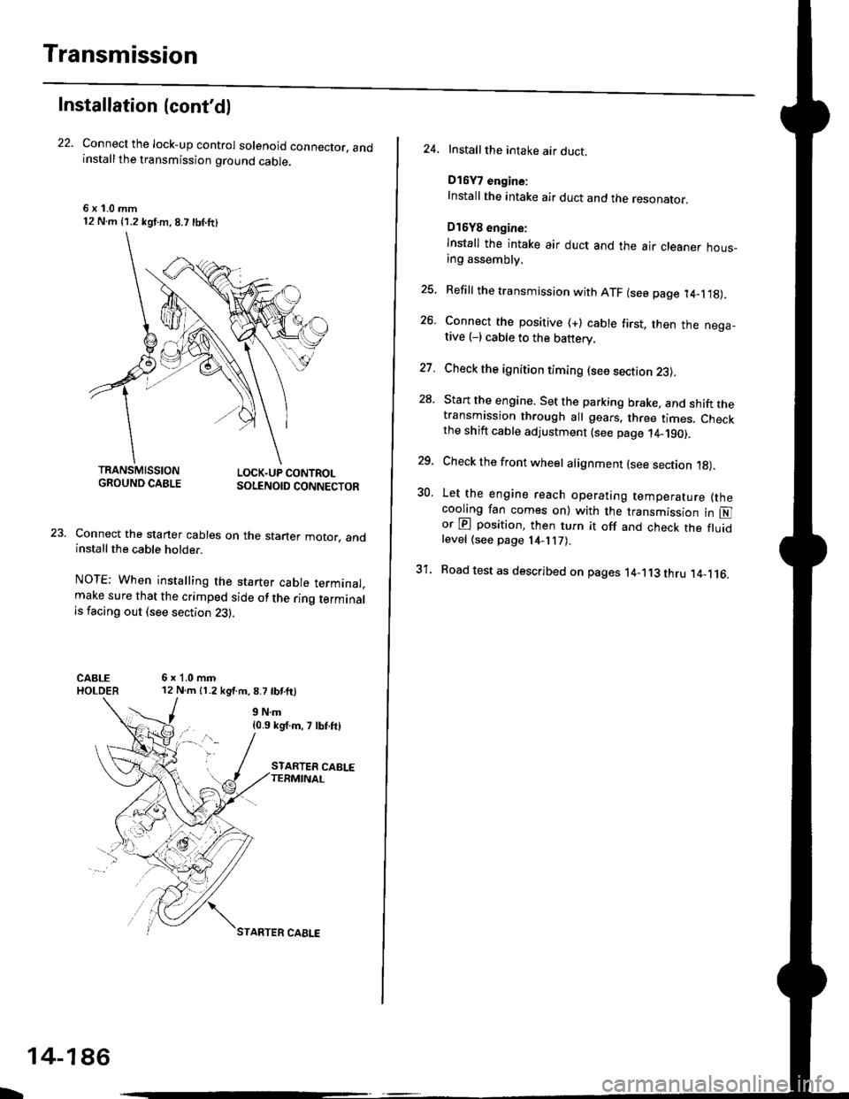
Connect the lock-up control solenoid connector. andinstall the transmission ground cable.
6 x '1.0 mm12 N.m {1.2 kgf.m, 8.7 lbl.ft}
LOCK.UP CONTROLSOLENOID CONNECTOR
Connect the staner cables on the staner motor. andinstall the cable holder.
NOTE; When installing the starter cable terminal.make sure that the crimped side of the ring terminalis facing out (see section 23).
6x1.0mm12 N.m 11.2 kg{.m.8.7 tbtftl
{0.9 kg'f.m, 7 lbf.ftl
TRANSMISSIONGROUND CABLE
b
14-186
STARTER CAELE
24. Installthe intake air duct.
D16Y7 engine:
Install the intake air duct and the resonaror.
D16Y8 engine:
lnstall the intake air duct and the air cleaner hous_ang assembly.
25. Refill the transmission with ATF (see page 14_1.18).
26. Connect the positive (+) cable first. then the nega-tive (-) cable to the battery.
27. Check the ignition timing (see section 23).
28. Start the engine. Set the parking brake, and shift thetransmission through all gears. three times. Checkthe shift cable adjustment (see page 14_190).
29, Check the front wheel alignment (see section 1g).
30. Let the engine reach operating temperature (thecooling fan comes on) with the transmission in Nor @ position, then turn it off and check the fluidlevel (see page 14- 7).
31. Road test as described on pages 14-113 thru ,14_116.
Page 868 of 2189
Shift Cable
Adjustment
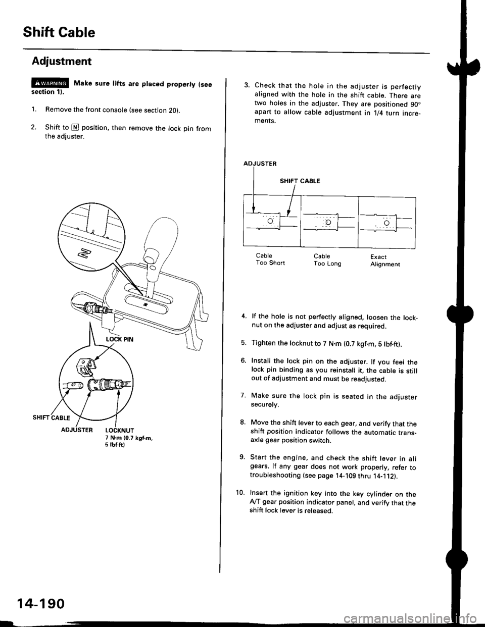
@ Make sure lifts are ptaced properly (see
section 1).
1. Remove the front console (see section Z0l.
2. Shift to @ position. then remove the lock pin fromthe adiuster.
7 N.m (0.75 tbtftlkgtm.
14-190
3. Check that the hole in the adjuster is perfectlyaligned with the hole in the shift cable. There aretwo holes in the adjuster. They are positioned 90.apart to allow cable adjustment in 1/4 turn incre-ments.
ExactAlignment
4. lf the hole is not perfectly aligned, loosen the lock-nut on the adjuster and adjust as required.
5. Tighten the tocknut to 7 N.m (0.7 kgf.m, 5 tbf.ft).
6. Install the lock pin on the adjuster. lf you feel thelock pin binding as you reinstall it, the cable is stillout of adjustment and must be readjusted.
7. Make sure the lock pin is seated in the adjustersecuretv.
8. Move the shift lever to each gear, and verify that theshift position indicator follows the automatic trans-axle gear position switch.
9. Start the engine, and check the shift lever in allgears. lf any gear does not work properly, refer totroubleshooting (see page 14-109 thru 1'4-'112).
10. Insert the ignition key into the key cylinder on theAy'T gear position indicator panel, and verify that theshift lock lever is released.
CableToo ShortCableToo Long
Page 874 of 2189
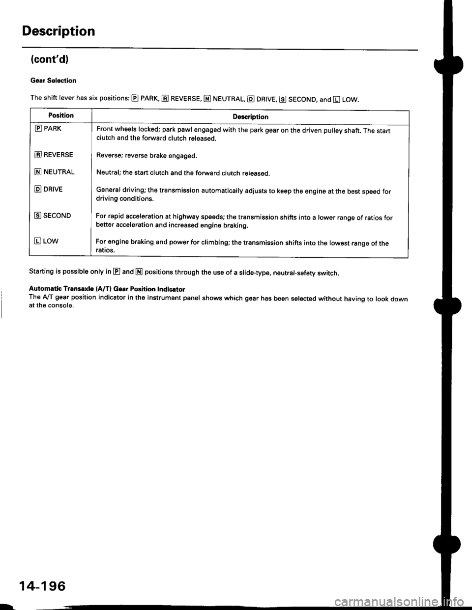
Description
(cont'd)
Gear Sel€stion
The shift lever has six positions: @ pARK, E REVERSE, E NEUTRAL, E DR|VE, g SECOND, and El LOW.
Staning is possible only in E and E positions through the use of a slid6-type, neutrafsafety switch.
Automrtic Transaxle {A/T} Gear Position Indicltor
The A-lT gear position indicator in the instrument panel shows which gear has been selected without having to look downat the console.
PoshionDe3cription
E PARK
E REVEBSE
E NEUTRAL
D DRIVE
E SECOND
E LOW
Front wheels locked; park pawl engaged with the park gear on the driven pulley shaft. The startclutch and the forward clutch released.
Reverse; reverse brake engaged.
Neutral; the start clutch and the forward clutch released.
General driving; the transmission automatically adjusts to keep the engine at the best speed fordriving conditions.
For rapid accelsration at highway speeds; the transmission shifts into a lower range of ratios forbetter acceleration and increased engine braking.
For engine braking and power for climbinO; the transmission shifts into the lowest range of theralros.
l-
14-196
Page 906 of 2189
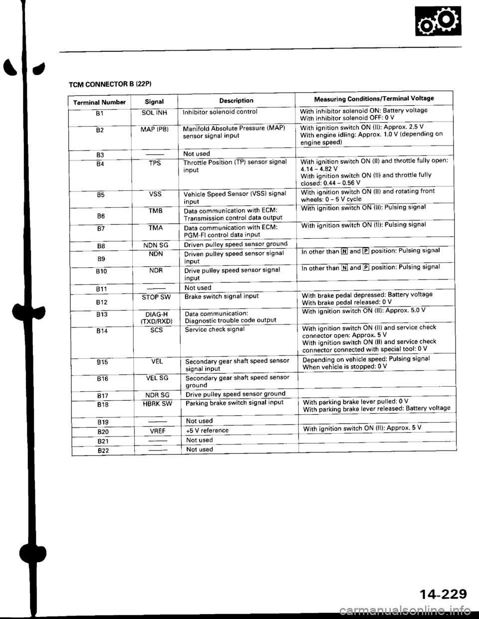
TCM CONNECTOR B (22P}
Terminal NumbelSignalDescriptionMeasuring Conditions/Terminal Voltage
B1SOL INHInhibitor solenoid controlWith inhibitor solenoid ON: Baftery voltage
With inhibitor solenoid OFF: 0 V
82MAP (PB)-M an if old Absol r-rte Pressure IMAP)
sensor signal inPUtWith iqnition switch ON (ll): Approx.2.5 V
With e;gine adling: Approx. 1.0 V (depending on
engine speed)
B3Not used
B4TPS-Throttle Position (TP) sensor signal
input
With ignition switch ON (ll) and throftle fully open:
4.14 - 4.42 VWith ignition switch ON (ll) and throttle fully
closed: 0.44 - 0.56 V
VSSVehicle Speed Sensor (VSS) signal
Inpur
With ignition switch ON (ll) and rotating front
wheelsr 0-5Vcycle
TMBData communication with ECM:
Transmission control data outpUt
With ignilion swltch UN lll): rulslng slgnar
81TMAData communication with EClvl:
PGM Fl control data inPut
With ignition swltch uN {ll,: l-ulslng slgnal
B8NDN SGDriven pulley speed sensor ground
B9NDNDriven pulley speed sensor signal
input
ln other thTnE and E position: Pulsing signal
810NDRDrive pulley speed sensor signal
Input
-tn ottrer ttran E ana E position: Pulsing signal
811Not used
812STOP SWBrake switch signal inPutWith brake pedal depressed: Battery voltage
With brake pedal released: 0 V
813DIAG-H(TXD/RXD)Data communication:Diagnostic trouble code outPut
Wittr ignitio.r s*itct' ON (ll): Approx 5.0 V
814Se-ice ctrect signatWith ignition switch ON (ll) and service check
connector oPen: APProx.5 V
With iqnition switch ON (ll) and service check
"onn"itot. connect"d with special tool: 0 V
Secondary gear shaft speed sensor
signal input
Depending on vehicle speed: Pulsing signal
When vehicle is stoPped: 0 V815VEL
816VEL SGSecondary gear shaft speed sensorgrouno
817NDR SGDrive pulley speed sensor ground
818HBRK SWParking brake switch signal inPutWith parking brake lever pulledr 0 V
With parking brake lever released: Battery voltage
819Not used
B�20VREF+5 V relerenceWith ignition switch ON (ll): Approx 5 V
821Not used
Not used