idle control system HONDA CIVIC 1998 6.G Owner's Manual
[x] Cancel search | Manufacturer: HONDA, Model Year: 1998, Model line: CIVIC, Model: HONDA CIVIC 1998 6.GPages: 2189, PDF Size: 69.39 MB
Page 535 of 2189
Emission Control System
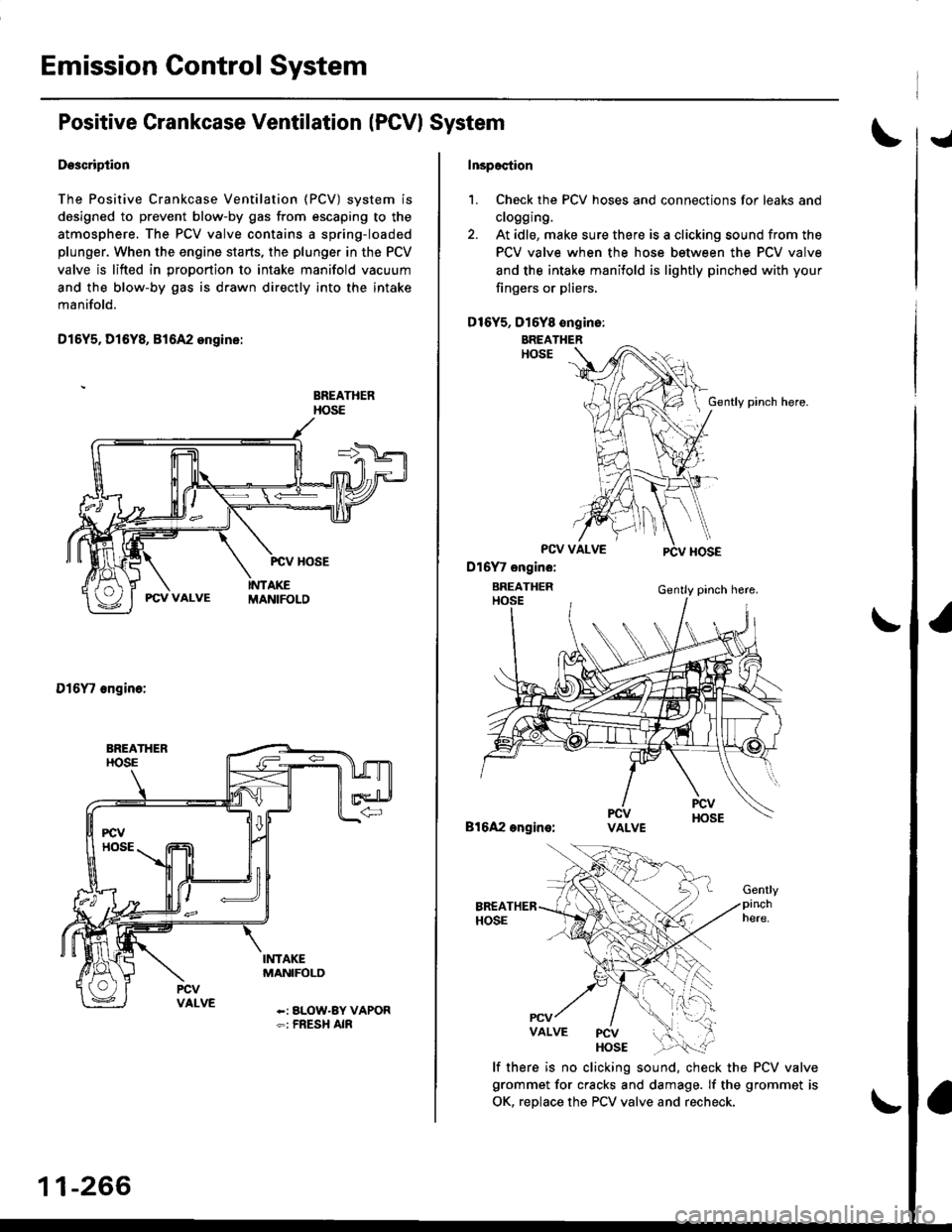
Positive Crankcase Ventilation IPCVI System
Descripiion
The Positive Crankcase Ventilation (PCV) system is
designed to prevent blow-by gas from escaping to the
atmosphere. The PCV valve contains a spring-loaded
plunger. When the engine starts, the plunger in the PCV
valve is lifted in proportion to intake manifold vacuum
and the blow-by gas is drawn directly into the intake
manifold.
D15Y5, D16Y8, 816A2 ongins:
BREATHERHOSE
Dl6'|11 6ngin6:
-: aLOW-BY VAPOR-: FnESH AIF
11-266
tJ
lrcpection
1. Check the PCV hoses and connections for leaks and
clogging.
2. At idle, make sure there is a clicking sound from the
PCV valve when the hose between the PCV valve
and the intake manifold is lightly pinched with your
fingers or pliers,
D16Y5, D16Y8 ongins:
BREATHERHOSE
PCV VALVE
Gently pinch here.
Bl6A2 engins:VALVE
lf there is no clicking sound, check the PCV valve
grommet for cracks and damage. If the grommet is
OK, replace the PCV valve and recheck.
PCV
Page 553 of 2189
Emission Control System
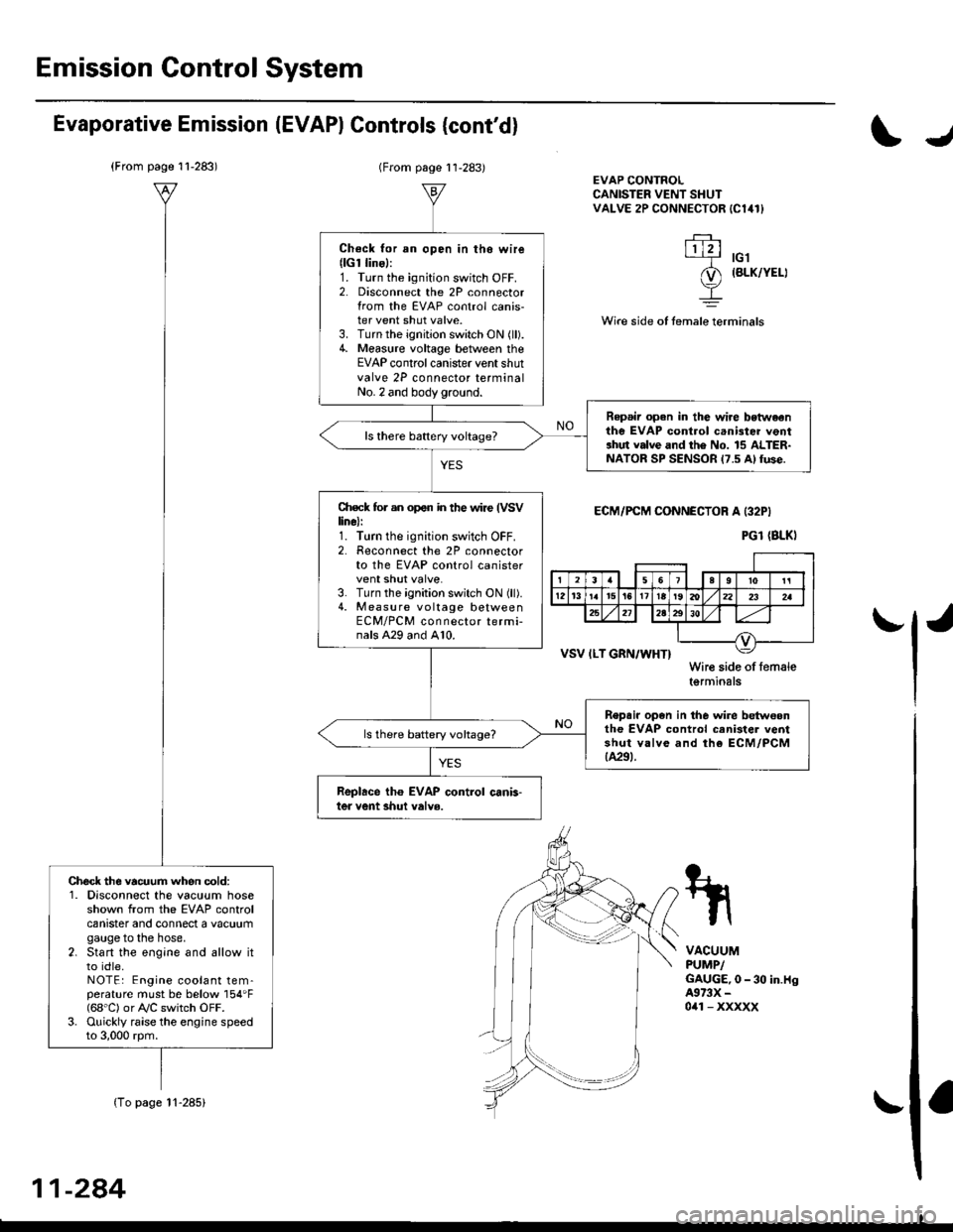
Evaporative Emission (EVAPI Controls (cont'dl
1
EVAP CONTROLCANISTER VENT SHUTVALVE 2P CONNECTOR IC141}
lltrt+ rcl
o) (8LK/YErl
I
temale terminalsWire side ot
ECM/PCM CONNECTOR A (32PI
VSV ILT GRN/WHT}
'l'
Wiro side of lemaletgrminals
VACUUMPUMP/GAUGE,0 - 30 in.Hg4973X -
041 - XXXXX
(From page 1l-283)
{To page 1l-285}
Check the vacuum whon cold:1. Disconnect the vacuum hoseshown from the EVAP controlcanrster and connect a vacuumgauge to the hose,2. Start the engine and allow itto idle.NOTE: Engine coolant tem-perature must be below 154oF(68'C) or lVC switch OFF.3. Ouickly raise the engine speedto 3,000 rpm.
(From page l1-283)
Check for an open in tho wire(lGl line):1. Turn the ignition switch OFF.2. Disconnect the 2P connectorlrom the EVAP control canis-ter vent shut valve.3. Turn the ignition switch ON (ll).4. Measure voltage between theEVAP controlcanister vent shutvalve 2P connector terminalNo. 2 and body ground.
Repair open in the wire betwe€nthe EVAP control c.ni3tei ventshut valve and th6 No. 15 ALTER-NATOR SP SENSOR 17.5 Al fuse.
Cfisck tor an opon in the wire (VSVline):1. Turn the ignition switch OFF.2. Beconnect the 2P connectorto the EVAP control canistervent shut valve.3. Turn the ignition switch ON (ll).4. Measure voltage betweenECM/PCM connector termi-nals A29 and Al0.
Rep.ir open in the wire betwoonthe EVAP control canister ventshut valve and th€ ECM/PCMtA29t.
ls there battery voltage?
Replace th6 EVAP control canis-ter vent 3hut valve.
PGT (BLKI
:lI23l'ltl'l lelsl ro Ir I1213t6€lnltlr@/lzzl zs f il
25
11-284
Page 559 of 2189
Emission Control System
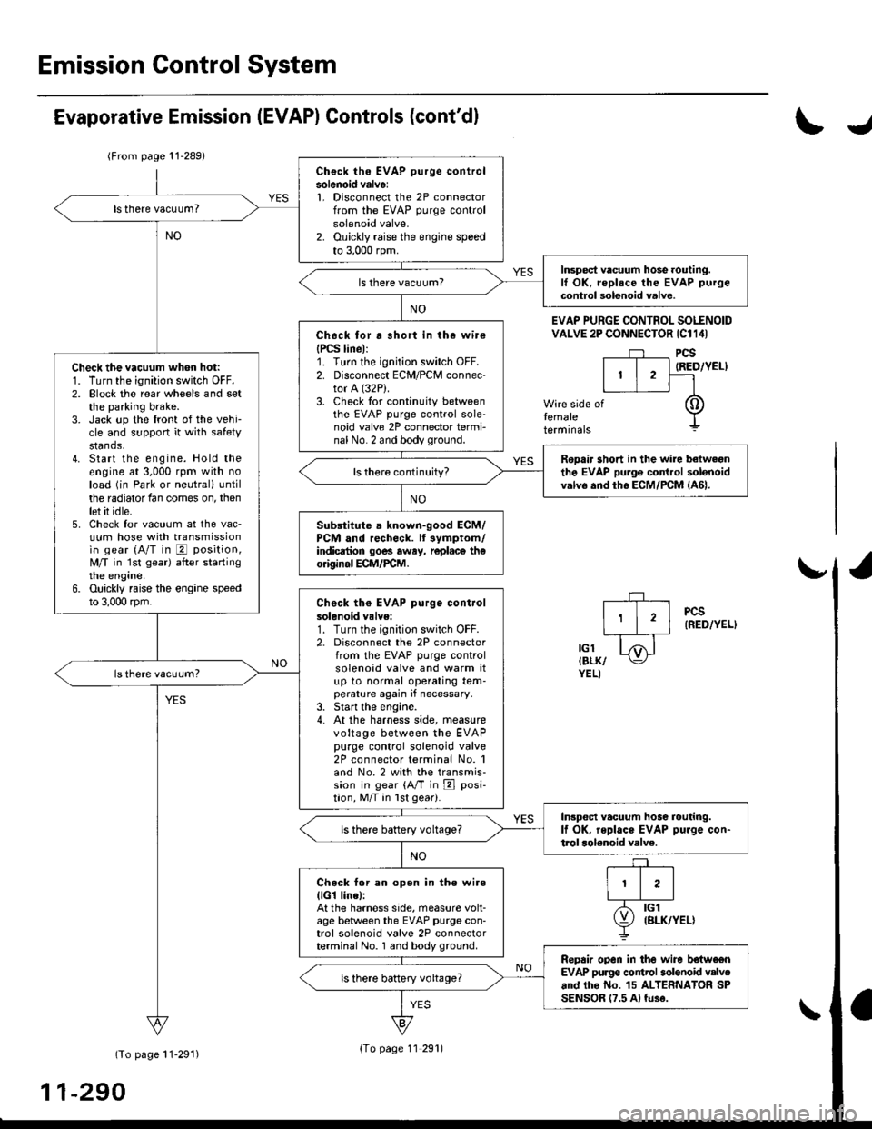
Ch€ck the EVAP purge controlsolenoid valv6:1. Disconnect the 2P connectorfrom the EVAP purge controlsolenoid valve.2. Ouickly raise the engine speedto 3,000 rpm.
Insped vacuum hose routing.lf OK. roplace the EVAP purge
control solonoid valve.
Chock tor r short in the wir€
{PCS line):1. Turn the ignition switch OFF.2. Disconnect ECM/PCM connec-tor A (32P).
3- Check tor continuity betweenthe EVAP purge control sole-noid valve 2P connector termi-nal No. 2 and body ground.
Check the vacuum when hot:1. Turn the ignition switch OFF.2. Block the rear wheels and setthe parking brake.3. Jack up the lront of the vehi-cle and support it with safetystands.4. Start the engine. Hold theengine at 3,000 rpm with noload (in Park or neutrali until
the radiator fan comes on, thenlet it idle.5. Check for vacuum at the vac-uum hose with transmissionin gear (A/T in E position,
lvl/T in 1st gear) after startingthe engine.6. Ouickly raise the engine speedto 3,000 rpm.
Rooair shoft in the wire belwegnthe EVAP pulg6 control solenoidvalvs and tho ECM/PCM {A61.ls there continuity?
Substitute a known-good ECM/PCM and rech6ck. lt 3ymptom/indicrtion 90e3 rway, r6plac6 th€o.iginal ECM/FCM.
Check th€ EVAP purge controlsolenoid valve:1. Turn the;gnition switch OFF.2. Disconnect the 2P connectorfrom the EVAP purge controlsolenoid valve and warm itup to normal operating tem-perature again if necessary.3. Start the engine.4- At the harness side, measurevoltage between the EVAPpurge control solenoid valve2P connector terminal No. 1and No.2 with the transmis-sion in gear {A/T in E posi-tion, M/T in lst geari.
In3pect vacuum hoae routing.lf OK, repl.ce EVAP purge con-trol solonoid valve.ls there battery voltage?
Chock for an open in the wire(lG1 lina):At the harnoss side, measure volt-age beNveen the EVAP purge con-trol solenoid valve 2P connectorterminal No. 1 and body ground.
Repair open in the wire b€lwe€nEVAP purge contrl 3olenoid valv6and lhe No. 15 ALTERNATOR SPSENSOR 17.5 A, fu3e.
ls there battery voltage?
Evaporative Emission (EVAPI Controls (cont'dl
(From page 11-289)
(To page 11-291)
11-290
IJ
EVAP PURGE CONTROL SOLENOIDVALVE 2P CONNECTOR IC114I
PCS
IRED/YEL)
temaletermrnars
of
PCS(RED/YEL)
tGlIBLK/YEL)
{To page 11 291)
Page 790 of 2189
Symptom-to-Component Chart
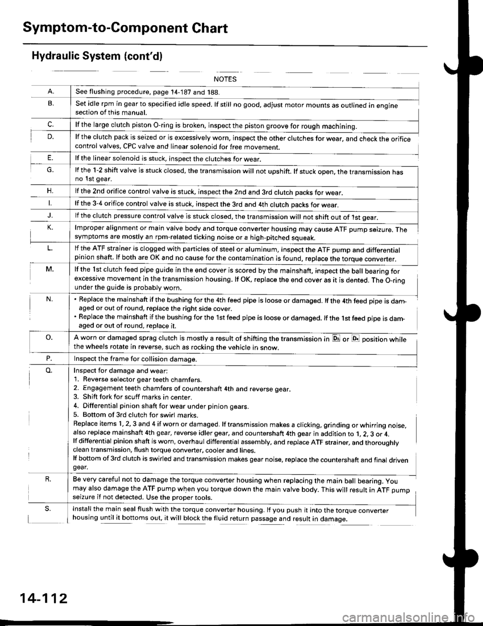
Hydraulic System (cont'dl
G.
n,
set idle rpm in gear to specified idle speed. lf still no good, adjust motor mounts as outlined in enginesection of this manual.
lf the clutch pack is seized or is excessively worn. inspect the other clutches for wear, and check the orificecontrol valves, CPC valve and linear solenoid for free movement.
lf the linear solenoid is stuck, inspect the clutches for wear.
lmproper alignment or main valve body and torque converter housing may cause ATF pump seizure. Thesymptoms are mostly an rpm-related ticking noise or a high-pitched squeak.
lf the l st clutch feed pipe guide in the end cover is scored by the mainshaft, inspect the ball bearing forexcessive movement in the transmission housing. lf oK, replace the end cover as it is dented. The o-rinounder the guide is probably worn.
Replace the mainshaft if the bushing for the 4th feed pipe is loose or damaged. lf the 4th feed pipe is danFaged or out of round, replace the right side cover.
Replace the mainshaft if the bushing for the 1st feed pipe is loose or damaged. lf the 1st feed pipe is darn-aged or out of round, replace it.
A worn or damaged sprag clutch is mostly a result of shifting the transmission inthe wheels rotate in reverse, such as rocking the vehicle in snow.
or E position while
Inspect for damage and wear:
1. Reverse selector gear teeth chamfers.
2. Engagement teeth chamfers of countershaft 4th and reverse gear.
3. Shift fork for scuff marks in center.
4. Differential pinion shaft for wear u nder pin ion gears.
5. Bottom of 3rd clutch for swirl marks.
Replace items 1,2,3 and 4 if worn or damaged. lf transmission makes a clicking, grinding orwhirring noise,also replace mainshaft 4th gear, reverse idler gear. and countershaft 4th gear in addition to 1, 2, 3 or 4.lf differential pinion shaft is worn, overhaul differential assembly, and replace ATF strainer, and thoroughlyclean transmission, flush torque converter, cooler and lines.lf bottom of 3rd clutch is swirled and transmission makes gear noise, replace the countershaft and final drivengear.
Be very careful not to damage the torque converter housing when replacing the main ball bearing, you
may also damage the ATF pump when you torque down the main valve body. This will result in ATF pumpseizure if not detected. Use the oroper roors.
Install the main seal flush with the torque converter housing. lf you push it into the torque converterhousing until it bottoms out, it will block the fluid return passage and result in damage.
See flushing procedure, page 14-187 and 188.
lf the large clutch piston O-ring is broken, inspect the piston groove for rough machining.
lf the l-2 shift valve is stuck closed, the transmission will not upshift. lf stuck open, the transmission hasno 1st gear.
lf the znd orifice control valve is stuck. inspect the 2nd and 3rd clutch oacks for wear.
lf the 3-4 orifice control valve is stuck, inspect the 3rd and 4th clutch oacks for wear.
lf the clutch pressure control valve is stuck closed, the transmission will not shift out of 1st gear.
lf the ATF strainer is clogged with particles of steel or aluminum, inspect the ATF pump and differentialpinion shaft. lf both are OK and no cause for the contamination is found, replace the torque converter.
Inspect the frame for collision damage.
14-112
Page 970 of 2189
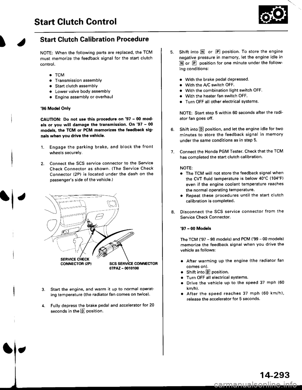
Start Clutch Control@
T
Start Clutch Calibration Procedure
NOTE: When the following parts are replaced, the TCM
must memorize the feedback signal for the start clutch
control.
. TCM
. Transmissionassembly
. Stan clutch assembly
. Lower valve bodv assembly
. Engine assembly or overhaul
'96 Model Only
CAUTION: Do not uso this procsdure on'97 - (X) mod-
els or you will damage the transmission. On '97 - 00
models, the TCM or PCM memorizes ths loodback sig'
nals when you drive the vehicle.
1. Engage the parking brake, and block the front
wheels securely.
2. Connect the SCS service connector to the Service
Check Connector as shown. (The Service Check
connector (2P) is located under the dash on the
passenger's side of the vehicle.)
CONNECTOR07PAZ - lDl01(xt
Start the engine, and warm it up to normal operat-
ing temperature (the radiator fan comes on twice).
Fully depress the brake pedal and accelerator for 20
seconds in the E] position.
rl ,
CONNECTOR I2PI
14-293
7.
Shift into E o|. E position. To store the engine
negative pressure in memory. Iet the engine idle in
E or E position for one minute under the follow-
ing conditions:
. With the brake pedal depressed,
. with the y'\/c switch oFF.
. With the combination light switch OFF.
. With the heater fan switch OFF.
. Turn OFF all other electrical systems
NOTE: Start step 5 within 60 seconds after the radi-
ator fan goes off.
Shift into E position, and let the engine idle for two
minutes to store the feedback signal in memory
under the same conditions as in step 5.
Connect the Honda PGM Tester. Check that the TCM
has completed the start clutch calibration.
NOTE:
. The TCM will not store the feedback signal when
the CVT fluid temperature is below 40"C (104'F)
even if the engine coolant temperature reaches
the normal operating temperature.
. Repeat these procedures until the start clutch
calibration is completed-
Disconnect the SCS service connector from the
Service Check Connector.
'97 - 00 Models
The TCM ('97 - 98 models) and PCM ('99 - 00 models)
memorize the feedback signal when you drive the
vehicle as follows:
. After warming up the engine (the radiator fan
comes onl.
. Shift into E position.
. Turn OFF all electrical systems,
. Drive the vehicle up to the speed 37 mph (60
km/h).
. After the speed reaches 37 mph (60 km/h),
release the accelerator for 5 seconds.
Page 1081 of 2189
/
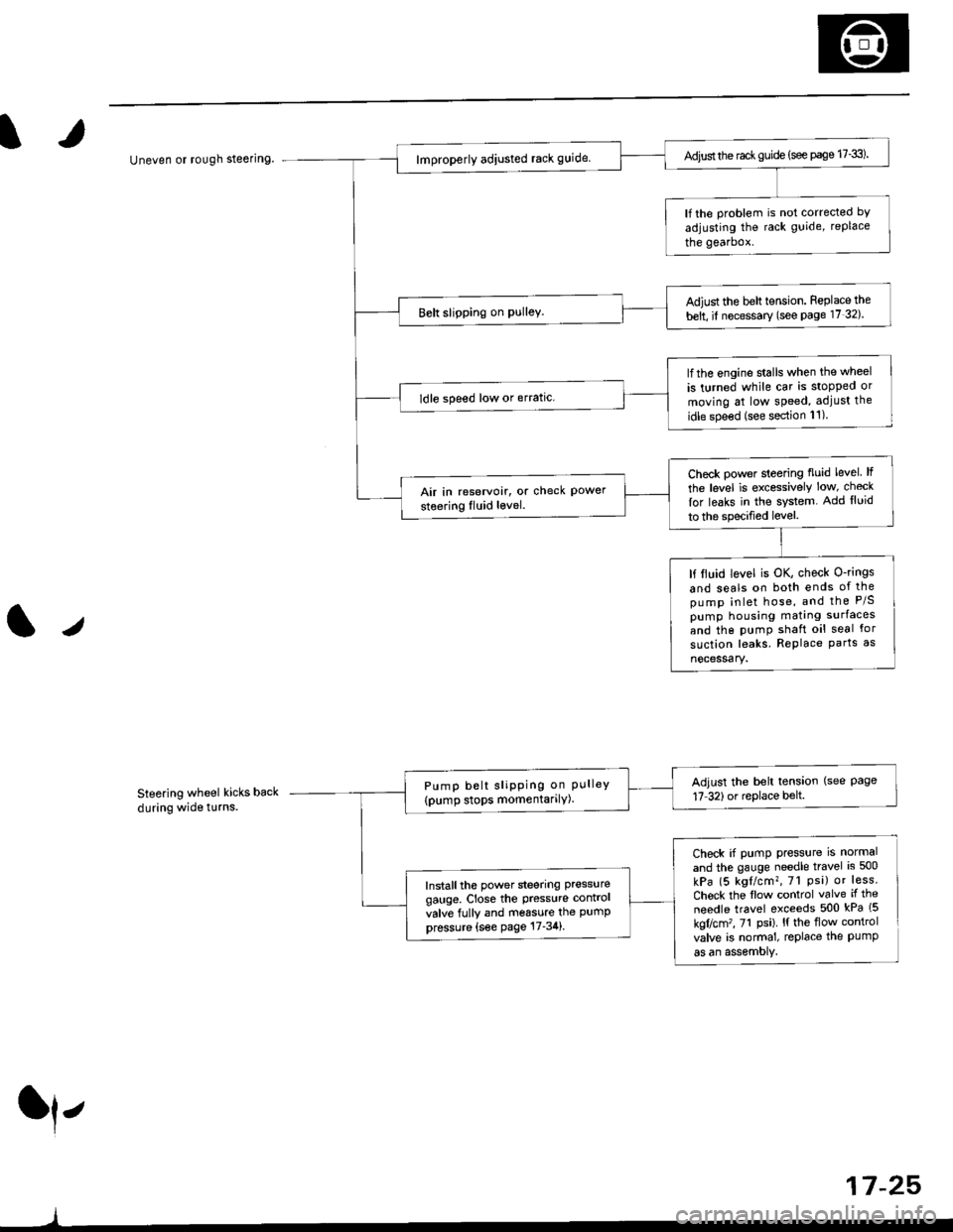
Uneven or rough steering
Steering wheel kicks back
during wide t!rns.
ll,
)
Adjust the rac* guide (see page 17-3).
lf the problem is not corrected bY
adjusting the rack guide, replace
the gearbox.
Adiust the belt tension. Feplace the
belt, il necessary (see Page 17 32).
lfthe engine stalls when the wheel
is turned while car is stopped or
moving at low speed, adjust the
idle spe€d (see section 11)
ldle speed low or erratic.
Check power sleering fluid level lf
the level is excessively low, check
lor leaks in the system. Add lluid
to the specified level.
Air in reservoir, or check Powersteering Iluid level.
lf ltuid level is OK, check O-rings
and seals on both ends of thepump inlet hose, and the P/Spump housing mating surfaces
and the pumP shaft oil seal for
suction leaks. RePlace Parts as
nocessary.
Adjust the belt tension (see Page17 32)or replace belt.Pump belt sliPPing on PLrlleY(pump stops momentarilY)
Check if pump press{rre is normal
and the gauge needle travel is 500
kPa (5 kgl/cm?, 7l Psi) or less.
Chock the flow control valve if the
needle travel exceeds 500 kPa (5
kgflcm'�, 71 Psi). l{ the flow control
valve is normal, replace the PumPas an assemoly.
Install the power steering pressure
gauge, Close the Pressure contrcl
valve fully and m6ssure the PumPpressure {s€e page 17-34}.
17 -25,
Page 1177 of 2189
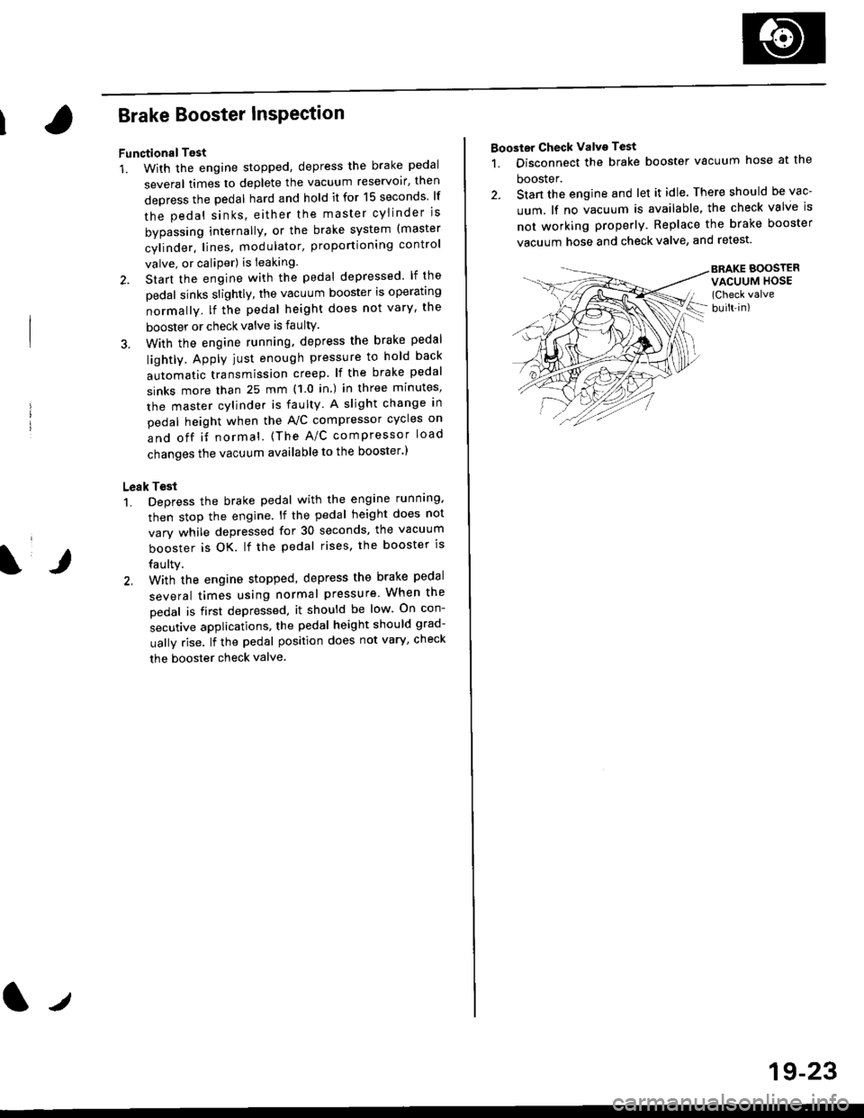
Brake Booster InsPection
FunctionalTest
1. With the engine stopped, depress the brake pedal
several times to deplete the vacuum reservoir, then
depress the pedal hard and hold it for 15 seconds lf
the pedal sinks' either the master cYlinder is
bypassing internally, or the brake system (master
cylinder. lines. modulator, proportioning control
valve, or caliPer) is ieaking.
2. Start the engine with the pedal depressed lf the
pedal sinks slightly, the vacuum booster is operating
normally. lf the pedal height does not vary, the
booster or check valve is faultY.
3. With the engine running. depress the brake pedal
lightly. Apply just enough pressure to hold back
automatic transmission creep. lf the brake pedal
sinks more than 25 mm (1.0 in.) in three minutes,
the master cvlinder is faulty. A slight change in
pedal height when the A'lC compressor cycles on
and off if normal. (The A/C compressor load
changes the vacuum available to the booster')
Leak Test
1. Depress the brake pedal with the engine running.
then stop the engine. lf the pedal height does not
vary while depressed for 30 seconds, the vacuum
booster is OK. lf the pedal rises. the booster is
faulty.
2, With the engine stopped, depress the brake pedal
several times using normal pressure When the
Dedal is first depressed, it should be low On con-
secutive applications, the pedal height should grad-
uallv rise. lf the pedal position does not vary, checK
the booster check valve.
l./
19-23
Booster Check Valve Test
1. Disconnect the brake booster vacuum hose at the
booster.
2. Stan the engine and let it idle. There should be vac-
uum. lf no vacuum is available, the check valve is
not working properly. Replace the brake booster
vacuum hose and check valve, and retest.
BRAKE BOOSTERVACUUM HOSE(Check valve
built-in)
Page 2137 of 2189
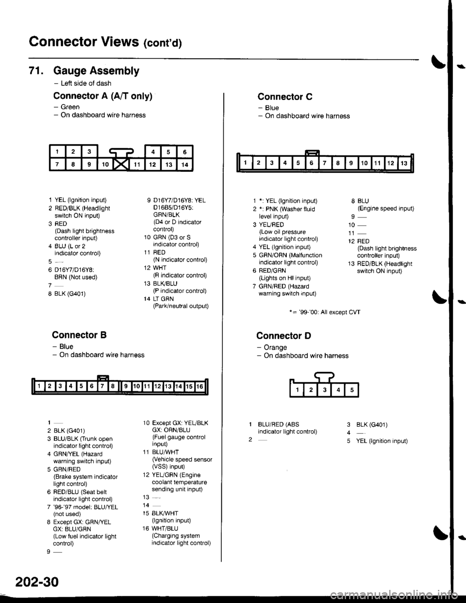
Connector Views (conrd)
71. Gauge Assembly
- Left side of dash
Connector A (A/T only)
- Green- On dashboard wire harness
1 YEL (lgnition input)
2 RED/BLK (Headlight
switch ON input)
3 RED(Dash light brightnesscontroller input)
4 BLU (L or 2indicator control)
6 D16Y7/D16Y8:BRN (Not used)
8 BLK (G401)
Connector B
- Blue- On dashboard wire harness
2 BLK (G401)
3 BLU/BLK (Trunk openindicator light control)
4 GRN/YEL (Hazard
warning switch input)
5 GRN/RED(Brake system indicatorlight control)
6 RED/BLU (Seat beltindicator light control)
7 '96-'97 model: BLU,ryEL(not used)
8 Except GX: GRN/YELGX: 8LU/GRN(Low fuel indicator lightcontrol)
9 D16Y7/D16Y8: YEL01685/016Y5:GRN/BLK(D4 or D indicatorcontrol)
10 GRN (03 or Sindicator control)
11 RED(N indicator control)
12 WHT(F indicator control)
13 BLI(BLU(P indicator control)
14 LT GBN(Park/neutral output)
10 Except GX: YEUBLKcX: ORN/BLU(Fuel gauge controlinput)
11 BLUAVHT(Vehicle speed sensor(VSS) input)
12 YEUGRN (Engine
coolant temperaturesending unit input)
14
15 BLI(IVHT(lgnition input)
16 WHT/BLU(Charging systemindicator light control)
202-30
Connector C
- Blue- On dashboard wire harness
1 *: YEL (lgnition input)
2 *: PNK (Washer lluidlevel input)
3 YEUBED(Low oil pressureindicator light control)
4 YEL (lgnition input)
5 GRN/ORN (Malfunctionindicator light control)
6 RED/GRN
{Lights on Hl input)
7 GBN/RED (Hazardwarning switch input)
*= '99-'00: All except CVT
Connector D
- Orange- On dashboard wire harness
BLU/RED (ABS
indicator light control)
8 BLU(Engine speed input)
10
12 FED(Dash light brightnesscontroller input)
13 RED/BLK (Headlightswitch ON input)
I
2
3
4
5
BLK (G401)
YEL (lgnition input)