mainshaft HONDA CIVIC 1998 6.G Owner's Manual
[x] Cancel search | Manufacturer: HONDA, Model Year: 1998, Model line: CIVIC, Model: HONDA CIVIC 1998 6.GPages: 2189, PDF Size: 69.39 MB
Page 616 of 2189
Mainshaft Thrust Shim
Adjustment
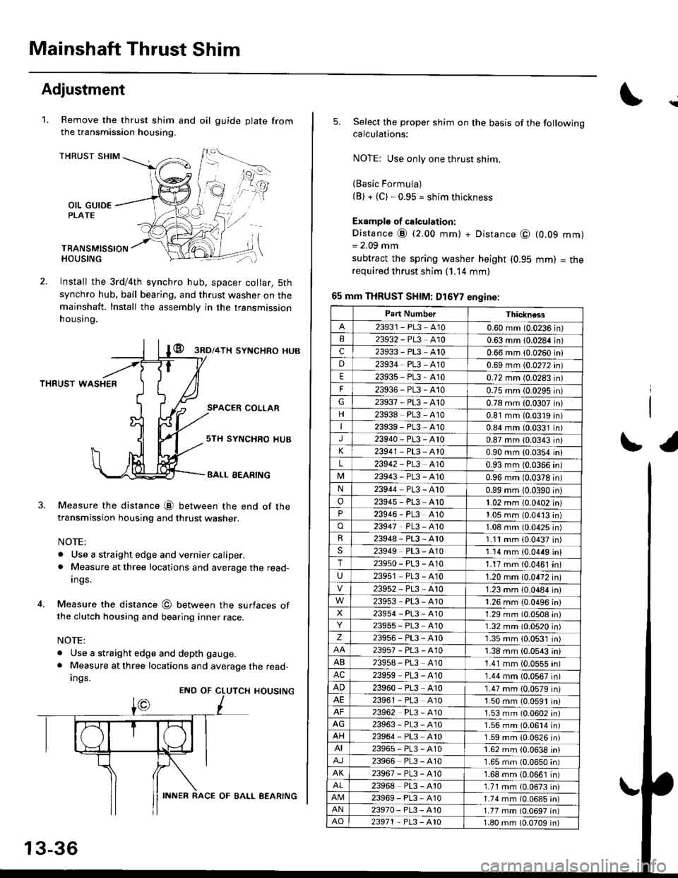
Remove the thrust shim and oil
the transmission housing.
1.gu ide plate from
THRUST SHIM
OIL GUIDEPLATE
TBANSMISSIONHOUSING
Install the 3rd/4th synchro hub, spacer collar, 5th
synchro hub, ball bearing, and thrust washer on themainshaft. Install the assembly in the transmission
h ousing.
@ gnol+lx syNcHRo HUB
THRUST WASHER
SPACER COLLAR
4.
Measure the distance @ between the end of thetransmission housing and thrust washer.
NOTE:
. Use a straight edge and vernier caliper.. Measure at three locations and average the read-
Ings.
Measure the distance @ between the surfaces ofthe clutch housing and bearing inner race.
NOTE:
. Use a straight edge and depth gauge.
. Measure at three locations and average the read-
Ings.
sTH SYNCHRO IIUB
BALL EEARING
CLUTCH
L
HOUSINGENO OF
13-36
INNER RACE OF BALL AEARING
\
5.Select the proper shim on the basis of the followingcalculations:
NOTE: Use only one thrust shim.
(Basic Formula)(B) + {C). 0.95 = shim thickness
Example of calculation:
Distance @ (2.00 mm) + Distance @= 2.09 mm
subtract the spring washer height (0.95
required thrust shim (1.14 mm)
65 mm THRUST SHIM: D16Y7 engine:
(0.09
mm)
mm)
= tne
r1
Part NumborThickness
23931 - PL3 A100.60 mm (0.0236 in)23932 - PL3 A100.63 mm 10.0284 in)c23933 - PL3 A100.66 mm {0.0260 iniD23934 PL3 - A100.69 mm (0.0272 in)
E23935-PL3-4100.72 mm 10.0283 in)
F23936-PL3-4100.75 mm 10.0295 in)G23937-PL3-A100.78 mm {0.0307 in}
23938 PL3 - A100.81 mm (0.0319 in)I23939 - PL3 At00.84 mm (0.0331 in)J23940-PL3-Ar00.87 mm (0.0343 in)
23941 - PL3 - A100.90 mm (0.0354 in)
L23942 - PL3 A100.93 mm (0.0366 in)
23943-PL3-A100.96 mm (0.0378 in)N23944 PL3 - A100.99 mm 10.0390 in)
o23945-PL3-A101.02 mm {0.0402 in}23946 - PL3 A101.05 mm (0.0413 in)o23947 PL3 - 4101.08 mm (0.0425 in)R23948-PL3-A101.11mm (0.0437 in)s23949 PL3 - A101.14 mm {0.0449 in}T23950-PL3-A101.17 mm (0.0461 in)
U23951 PL3 - A101.20 mm (0.0472 in)
23952-PL3-Ar01.23 mm {0.0484 in)
23953-PL3-A101.26 mm {0.0496 in}X23954 - P13, A101.29 mm (0.0508 in)23955 - PL3 A101.32 mm (0.0520 in)z23956-PL3-Ar01.35 mm {0.0531 in)
23957-PL3-A101.38 mm (0.0543 in)
AB239s8 - PL3 A101.41 mm (0.0555 in)AC23959 PL3 - A101.44 mm (0.0567 in)
AD23960 - PL3 A101.47 mm (0.0579 in)23961 - PL3 4101.50 mm (0.0591 in)23962 PL3 - A101.53 mm (0.0602 in)AG23963-PL3-4101.56 mm (0.0614 in)AH23964 - PL3 A101.59 mm (0.0626 in)AI23965-PL3-A101.62 mm {0.0638 in)
23966 PL3 - A101.65 mm (0.0650 in)AK23967-PL3-A101.68 mm {0.0661 in)
23968 PL3 - A101.71 mm {0.0673 in)23969-PL3-A101.74 mm (0.06a5 iniAN23970- PL3 -A101.77 mm (0.0697 in)AO23971 - PL3 - A101.80 mm 10.0709 in)
Page 617 of 2189
70 mm THRUST SHIM: Dl6Y5, Dl6Y8 engin€s
Part NumberThickness
23931 - PL3 - 8000.60 mm 10.0236 in)
23932-PL3-8000.63 mm (0.0284 in)
c23933-PL3-8000.66 mm (0.0260 in)
D23334-PL3-8000.69 mm 10.0272 in)
E23935-PL3-8000.72 mm (0.0283 in)
F23936 - PL3 8000.75 mm (0.0295 in)
23937-PL3-B000.78 mm (0.0307 in)
23938-PL3-8000.81 mm (0.0319 inl
23939-PL3-8000.84 mm (0.0331 in)
23940-PL3-8000.87 mm {0.0343 in)
23941 - PL3 - 8000.90 mm (0.0354 in)
L23942-PL3-8000.93 mm (0.0366 in)
23943-PL3-8000.96 mm (0.0378 in)
N23944-PL3-8000.99 mm i0.0390 in)
o2394s-PL3-8001.02 mm (0.0102 in)
P23946-PL3-8001.05 mm {0.0413 in}
o23947-PL3-8001.08 mm (0.0{25 in)
23948 - PL3 800'1.1'1 mm (0.0437 4n)
23949-PL3-8001.14 mm (0.0449 inl
T23950-PL3-8001.17 mm (0.0461 in)
23951 - PL3 - 8001.20 mm (0.0472 in)
23952-PL3-8001.23 mm (0.0444 in)
239s3-PL3-8001.26 mm {0.0496 in)
X23954-PL3-8001.29 mm (0.0508 in)
2395s-PL3-8001.32 mm (0.0520 in)
z23956-PL3-8001.35 mm (0.0531 in)
23957-PL3-8001.38 mm (0.0543 in)
A823958-PL3-8001.41 mm (0.0555 in)
AC23959-PL3-8001.44 mm {0.0567 in)
AD23960-PL3-8001.47 mm (0.0579 in)
2396'�t-PL3-8001.50 mm (0.0591 in)
23962-PL3-8001.53 mm (0.0602 in)
AG23963-PL3-8001.56 mm (0.0614 in)
AH23964-PL3-8001.59 mm (0.0626 in)
23965-PL3-8001,62 mm (0.0638 in)
23966-PL3-8001.65 mm (0.0650 in)
AK23967-PL3-8001.68 mm (0.0661 in)
23968-PL3-8001.71 mm (0.0673 in)
23969-PL3-8001.74 mm (0.0685 in)
AN23970-PL3-8001.77 mm (0.0697 in)
AO23971- PL3 8001.80 mm (0.0709 inl
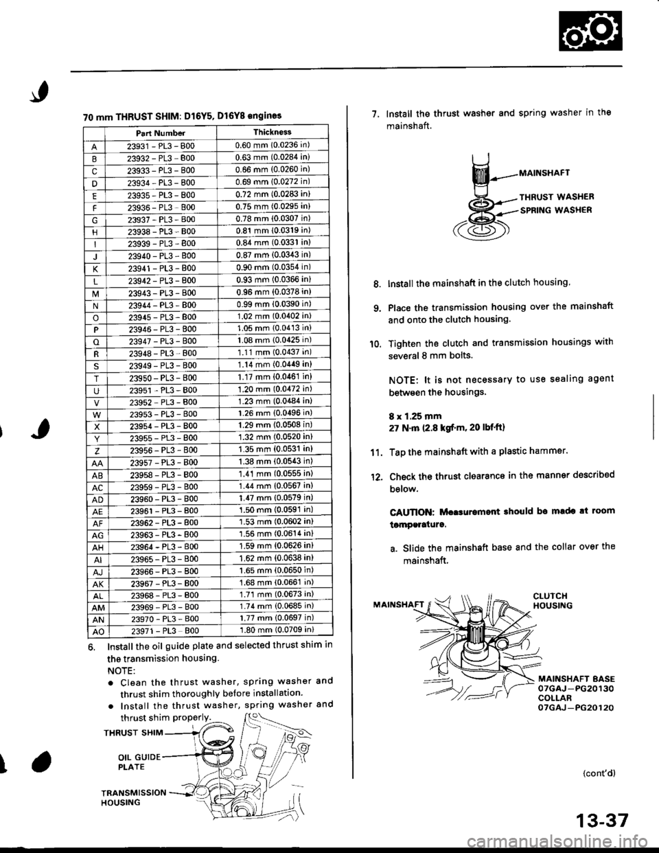
6. Installthe oil guide plate and selected thrust shim in
ths transmission housing
NOTE:
. Clean the thrust washer, spring washel and
thrust shim thoroughly belore installation.
. lnstall the thrust washer, spring washer and
thrust shim proPerlY.
THRUST SHIM
I
OIL GUIDEPLATE
TRANSMISSIONHOUSING
8.
o
10.
7, Install the thrust washer and spring washer in the
mainshaft.
lnstall the mainshaft in the clutch housing
Place the transmission housing over the mainshaft
and onto the clutch housing.
Tighten the clutch and transmission housings with
several 8 mm bolts.
NOTE: lt is not necessary to use sealing agent
between the housings'
8 x 1.25 mm
27 N'm t2.8 kgf.m. 20 lbf'ft)
Tap the mainshaft with a plastic hammer.
Check the thrust clearance in the manner doscribsd
below.
CAUnON: Mc.suromont 3hould bo mlde !t room
tomp9laturs.
a. Slide the mainshaft base and the collar over the
mainshaft.
CLUTCHHOUSING
11.
lz.
MAITISHAFT BASE07GAJ-PG20130COLLAF07GAJ -PG20120
{cont'd}
13-37
THRUST WASHER
SPRING WASI{ER
Page 618 of 2189
Mainshaft Thrust ShimI
I
Adjustment (cont'dl
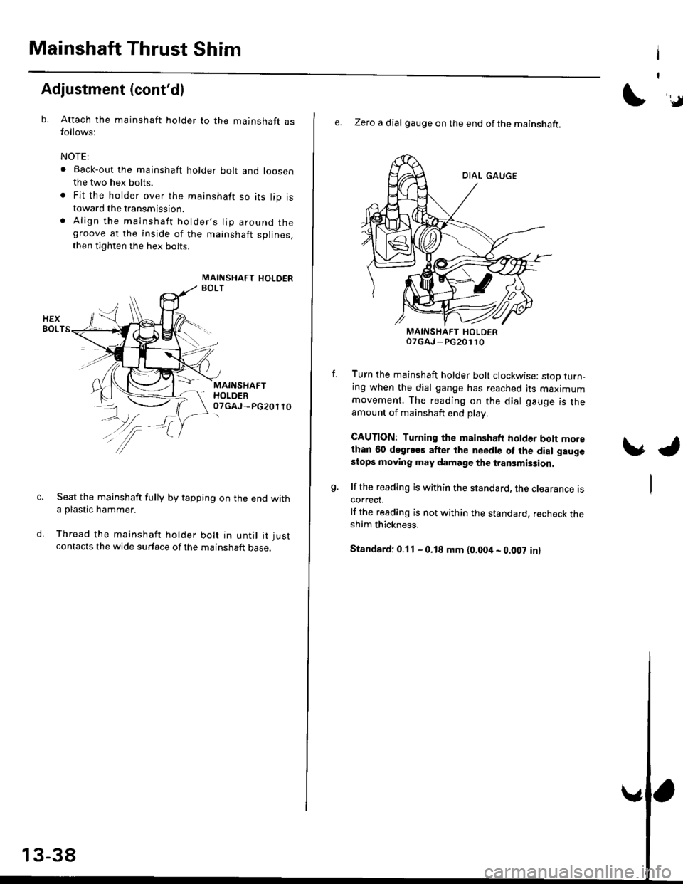
b.Attach the mainshaft holder to the mainshaft asfollows:
NOTEI
. Back-out the mainshaft holder bolt and loosen
the two hex bolts.
. Fit the holder over the mainshaft so its lip istoward the transmission.
. Align the mainshaft holder's lip around thegroove at the inside of the mainshaft splines,then tighten the hex bolts.
MAINSHAFT HOLOERBOLT
MAINSIIAFTHOLDER07GAJ-PG20110
d.
Seat the mainshaft fully by tapping on the end witha plastic hammer.
Thread the mainshaft holder bolt in until it just
contacts the wide surface of the mainshaft base.
u
e. Zero a dial gauge on the end ofthe mainshaft.
MAINSHAFT HOLDER07cAJ_PG20110
Turn the mainshaft holder bolt clockwise: stop turn,ing when the dial gange has reached its maximummovement. The reading on the dial gauge is theamount of mainshaft end olav.
CAUTION: Turning the mainshaft holder bolt morethan 60 degre€s after the needle ot the dial gauge
stops moving may damage the iransmission.
lf the reading is within the standard. the clearance iscorrecl.
lf the reading is not within the standard, recheck theshim thickness.
Standard: 0.11 - 0.18 mm {0.00it - 0.007 in}
t.
\,J
Page 620 of 2189
Transmission
Reassembly lcont'dl
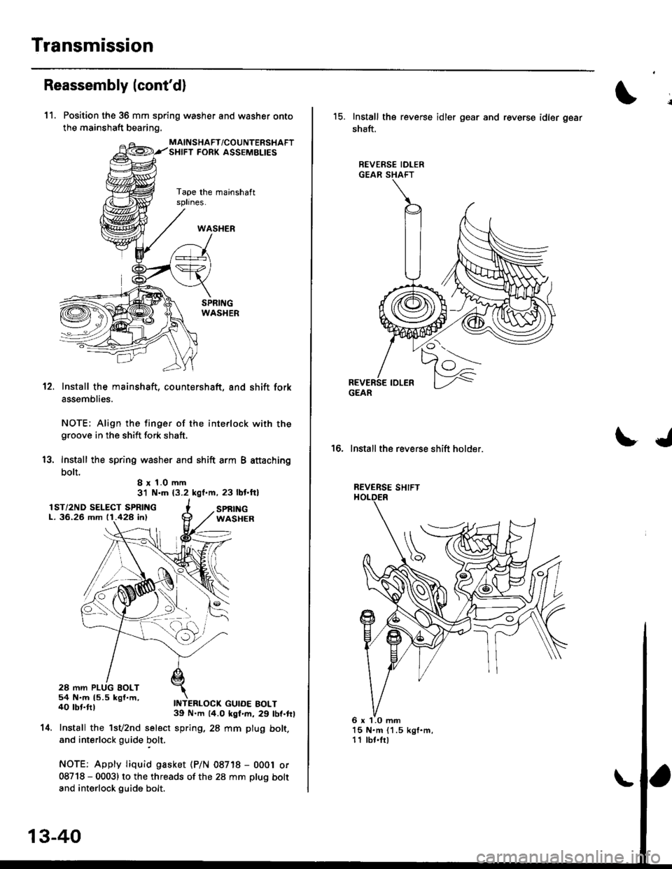
11. Position the 36 mm spring washer and washer onto
the mainshaft bearing.
MAINSHAFT/COUNTERSHAFTSHIFT FORK ASSEMELIES
Tape the mainshaftsplines.
12.
13.
Install the mainshaft, countershaft, and shift fork
assemblies.
NOTE; Align the finger of the interlock with thegroove in the shift fork shaft,
lnstall the spring washer and shift arm B attaching
bolt.I x 1.0 mm31 N.m (3.2 kgl.m, 23 lbt.ft)
IST/2ND SELECT SPRINGL. 36.26 mm 11.428 in)
54 N.m 15.5 kgf.m,40 tbt.ftl
SPf,INGWASHER
GUIDE BOLT
14.
39 N.m 14.0 kgf.m, 29 lbf.frl
Install the 1sv2nd select spring, 28 mm plug bolt.
and interlock guide bolt,
NOTE: Apply Iiquid gasket (P/N 08718 - 0001 or
08718 - 0003) to the threads of the 28 mm plug bolt
and interlock guide bolt.
13-40
15. Install the reverse idler gear and reverse idler gear
shaft.
REVERSE IDLERGEAR SHAFT
LJ16. Install the reverse shift holder.
REVERSE SHIFT
l5 N.m (1.5 kgf.m,11 lbt.trl
GEAR
6 x 1.0 mm
Page 625 of 2189
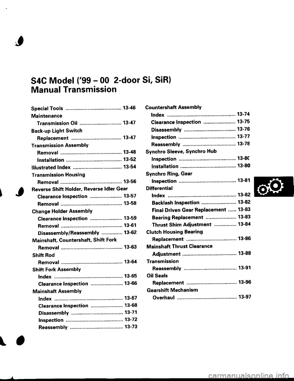
S4C Model ('99 - 00 2-door Si, SiR)
Manual Transmission
Special Tools ............' 13-46
Maintenance
Transmission Oi1 ...................'.......... 13-47
Back-up Light Switch
Repfacement ...""" 13'47
Transmission Assembly
Removal ......'.......... 13-/tB
lnstallation ............. 13-52
lllustrated lndex ................................... 13-54
Transmission Housing
Removal ................. 13-55
Beverse Shift Holder, Reverse ldler Gear
Clearance lnspection ...................".. 13-57
Removal ................. 13-58
Change Holder Assembly
Clearance lnspection .................".... 13-59
Removal ....,,........... 13-61
Disassembly/Reassembly ............... 1 3-62
Mainshaft, Countershaft, Shift Fork
Removal ................. 13-63
Shift Rod
Removal .........."'.... 13-64
Shift Fork Assembly
lndex ................ ...... 13-65
Clearance lnspection .............'......... 13'66
Mainshaft Assembly
lndex ............"" ...... 13-67
Clearance lnspection ....................... 13-68
Disassembly .......... 13-71
fnspection '."'.......', 13'72
Reassembly .......'... 13-73
Countershaft Assembly
fndex ................ "....13-71
Glearance Inspection'......'...........'... 1 3'75
Disassembly .......... 13-76
fnspection .'............13'77
Reassembly "......... 13'78
Synchro Sleeve, Synchro Hub
Inspection .............. 13'8C
Installation ............. 13-80
Synchro Ring, Gear
Inspection .'............ 13-81
Differential
lndex ................ ...... 13-82
Backlash Inspection ..."..........."'...... 1 3-82
Final Driven Gear Replacement ...... 13-83
Bearing Replacement ....."'.......""'.. 13-83
Thrust Shim Adiustment ......""'..... 13-84
Clutch Housing Bearing
Replacement ..'...... 13-86
Mainshaft Thrust Glearance
Adiustment '.........'. 13-88
Transmission
Reassembly ."'....... 13-91
Oil Seals
Replacement ..'...... 13-96
Gearshift Mechanism
Overhaul ................ 13-97
\
Page 626 of 2189
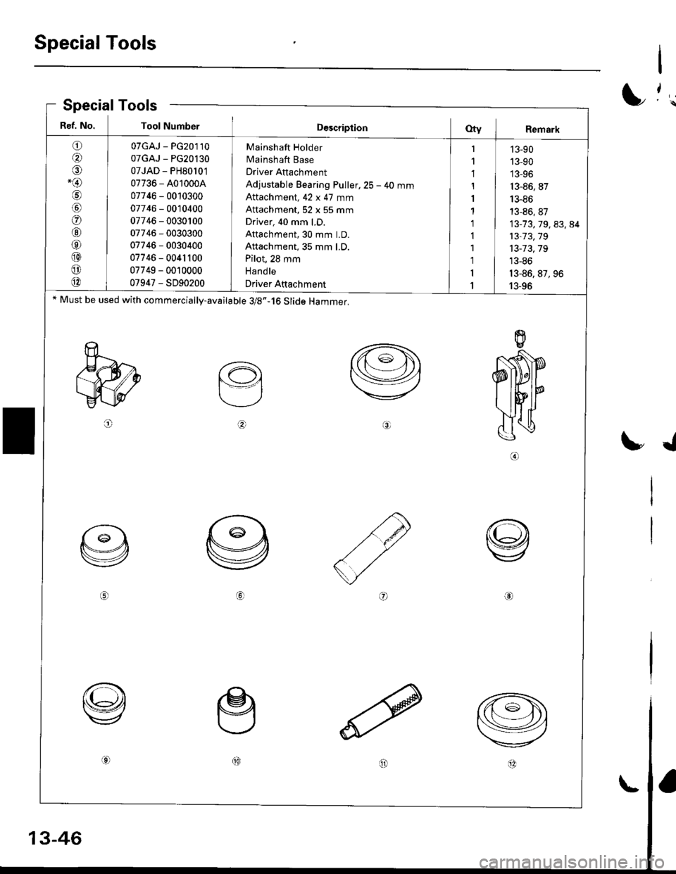
Special Tools
SpecialTools
I
I
I
./
Ref. No. Tool NumberD€scriptionOty I Remark
o
@
o-@
@
o
@
@
@
o
@
07GAJ - PG20110
07GAJ - PG20l30
07JAD - PH80l0'1
07736 - A010004
07746 - 0010300
07746 - 0010400
07746 - 0030100
07746 - 0030300
07746 - 0030400
07746 - 0041100
07749 - 0010000
07947 - SD90200
Mainshaft Holder
Mainshaft Base
Driver Attachment
Adjustable Bearing Puller,25 - 40 mm
Attachment, 42 x 47 mm
Attachment, 52 x 55 mm
Driver, 40 mm LD.
Attachment, 30 mm LD.
Attachment, 35 mm LD.
Pilot, 28 mm
Hand le
Driver Attachment
I
1
1
1
I
1'l
I
1
1
1'I
13-90
13-90
13-96
13-86, 87
13-86
13-86, 87
13-73,79,83,84
13-73,19
13-73,79
13-86
13-86,87,96
13-96* Must be used with commercially-available 3/8,,-16 Slide Hammer.
o
aol@(t4^
Page 631 of 2189
)
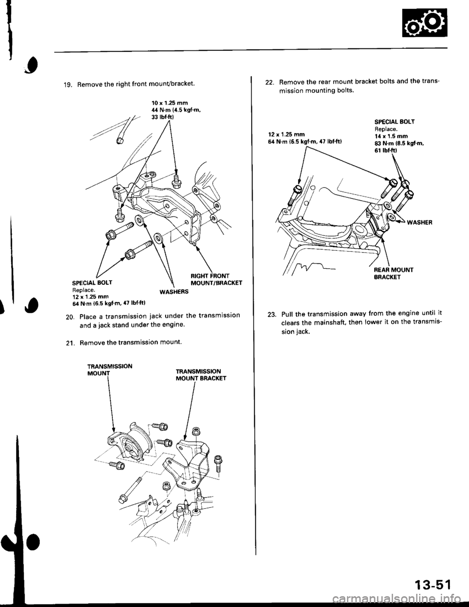
19. Remove the right front mounvbracket.
10 x 1 .25 mm,14 N.m {4,5 kgf.m,
WASHERS
20. Place a transmission jack under the transmission
and a jack stand under the engine.
21. Remove the transmission mount
SPECIAL BOLTReplace.12 x 1 .25 mm64 N.m 16.5 kgl'm, 47 lbf ftl
TRANSMISSION
3-51
22. Remove the rear mount bracket bolts and the trans-
mission mounting bolts
12 x 1.25 mm5{ N.m 16.5 kgf.m, 47 lbl.ft)
61
WASHER
23. Pull the transmission away from the engine until it
clears the mainshaft, then lower it on the transmis-
sion jack.
SPECIAL BOLTReplace.14 x 1.5 mm8il N.m (8.5 kgtm,
Page 635 of 2189
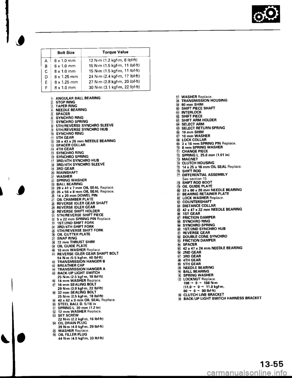
Bolt SizeTorque Value
cn
E
F
6x1.0mm
6x1.0mm
8 x 1.0 mm
8 x '1.25 mm
8 x 1.25 mm
8 x 1,0 mm
12 N.m (1.2 kgnm, 8 lbf'ft)
15 N.m (1.5 kgf'm, 11 lbf ft)
15 N.m (l.5 kgf.m, 11 lbift)
24 N'm (2.4 kgim, 17 lbift)
27 N.m (2.8 kgf.m,20 lbf'ft)
30 N.m (3.1 ksf m. 22 lbift)
5i WASHER Replace.6 TRANSMrssioN HouslNG!9 80 mm SHIM@ SHIFT PIECE SHAFT(6' INTERLOCK@ sHrFr PECE6} SHIFT ARM HOLDER@ seucr nnrvtI9 SELECT RETURN SPRING
@ 10 mm SHIM6, 10 mm WASHER@ LOCK COLLARi6sl 3 x l5 mm SPRING PIN Replace.t0 8 mm SPRING WASHERA) CHANGE PIECEll SPRING L.25.6 mm (1.01 in)'' MAGNET?4) CLUTCH HOUSINGta. 14 x 25 x 16 mm OIL SEAL Replace.A sHrFT BooO D|FFERENT|aL ASSEMBLYSee section 15iIO SHIFT ROD BOOT6 OIL GUIDE PLATE@ 33 x 60 x 20 mm NEEDLE BEASINGO BEARING RETAINER PLATElD LocK WASHER Replace..0 couNTERSHAFIA DISTANCE COLLAR6 & x 4I x 22 mm NEEDLE BEARING6. 1sr GEAR@ FRICTION DAMPERO SYNCHRO RING.d SYNCHRO SPRING@ 1ST/2ND SYNCHRO HUB..9i. REVERSE GEARC) DOUBLE CONE SYNCHROO FRICTION DAMPERS SPACER6 T2 x TI x 24 mm NEEDLE BEARING(!' 2ND GEAR61 3RD GEARiD 4TH GEAR@ 5TH GEAR(O NEEDLE BEARING(10 BALL BEARING@ SPRING WASHERf,o LoCKNUT Replace.108 - 0- 108 N'm111.0- 0* 11.0 kgf m,80* 0- 80lbI.ft)IO CLUTCH LINE BRACKET.d BACK.UP LTGHT SWITCH HARNESS BRACKET
:!, ANGULAR BALL BEABING:2, STOP RING:3] TAPER RING..-I NEEOLE BEARINGl!-- SPACERO SYNCHRO RING? SYNCHRO SPRINGE 5TH/REVERSE SYNCHRO SLEEVE...] sTH/REVERSE SYNCHRO HUB
O SYNCHBO EING.11-r sTH GEAR1A 38 x 43 x 26 mm NEEDLE BEARINGI13) SPACER COLLAR[!] /ITH GEAR.T5) SYNCHRO RING
O SYNCHRO SPRING17 3RD/4TH SYNCHRO HUB
O 3RD/4TH sYNcHRo SLEEVE
ii9 38D GEAR8I MAINSHAFT2i WASHERA SPRING WASH€R?I BALL BEARING.a4, 28 x 41 x 7 mm OIL SEAL Replace..2i 35 x 56 x 8 mm OIL SEAL Replace.t-t 14 x 20 mm DowEL PIN
.'] OIL CHAMBER PLATE
O REVERSE IDLER GEAR SHAFT.iI.., REVERSE IDLER GEAR'd REVERSE SHIFI HOLDERait srH/REVERSE sHIFT PIECE'34 5 x 22 mm SPRING PIN Replace.3' 1ST/2ND SHIFT FORK,34' 3RD/4TH SHIFT FORKi9t) srH/nevense sstrr ronx33 OIL GUTTER PLATE!' SNAP RING3d 72 mm THRUST SHIM
@ OIL GUIDE PLATE4t 10 mm WASHER Replaceti REVERSE TDLER GEAR SHAFT BoLT54 N.m {5.5 kgf m, 40lbIft)4N TBANSMISSION HANGER B43] BREATHER CAPA,J TRANSMISSION HANGER AIT' BACK-UP LIGHT SWITCH
I
25 N.m {2.5 kgl.m, 18lblftl14 mm WASHER RePlaceaO 14 mmtt 16 mm16 mm SEALING BOLT29 N.m (3.0 kgf m,22 lbf ft):4s) 32 mm SEALING BoLT25 N m 12.5 kgl m, 18 lbl'ft)40 x 62 x I mm OIL SEAL ReplaceSTEEL BALL D.5/15 iNSPRING L. 30 mm {1.2 in)12 mm WASHER Replace.SET SCREW22 N.m {2.2 kg{ m, 16 lbl ftlOIL DRAIN PLUG39 N.m {4.0 kgf m, 29lbtftlWASHER Replace.OIL FILLER PLUG4,t N.m {4.5 kgl m, 33 lblftl
.!rl00
@l
13-55
Page 636 of 2189
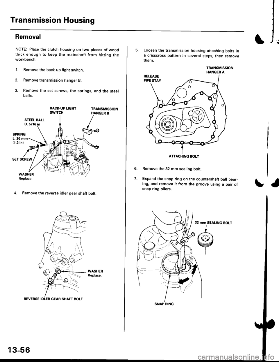
Transmission Housing
Removal
NOTE: Place the clutch housing on two pieces of wood
thick enough to keep the mainshaft from hitting theworkbench.
'1. Remove the back-up light switch.
2. Remove transmission hanger B.
3. Remove the set screws, the springs, and the steelballs.
BACK.UP UGHTswrTcH
SET SCREW
4. Remove the reverse idler gear shaft bolt.
WASHERReplace.
REVEBSE
13-56
5. Loosen the transmission housing attaching bolts ina crisscross pattern in several steps, then removethem.
TRANSMISSIONHANGER A
R€move the 32 mm sealing bolt.
Expand the snap ring on the countershaft ball bear-ing, and remove it from the groove using a pair ofsnap ring pliers,
32 mm SEALING BOLT
o.
1.
I{
ATTACHING BOLT
SNAP RING
Page 643 of 2189
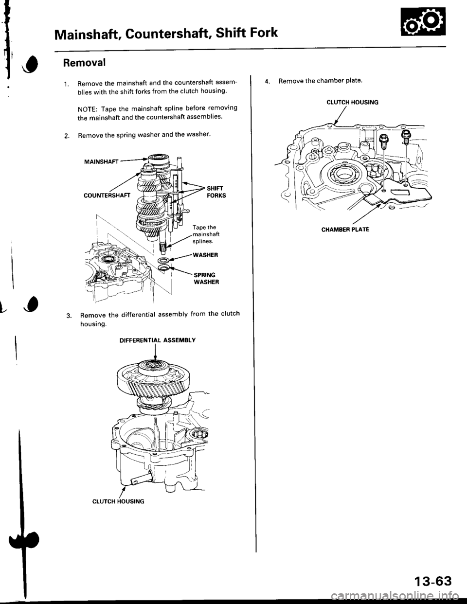
Mainshaft, Countershaft, Shift Fork
Removal
1.Remove the mainshaft and the countershaft assem-
blies with the shift forks from the clutch housing.
NOTE: Tape the mainshaft spline before removing
the mainshaft and the countershaft assemblies.
Remove the spring washer and the washer'
v
MAINSHAFT
COUNTERSHAFT
Remove the differential assembly from the clutch
housing.
Tape the
splrnes.
WASHER
DIFF€RENTIAL ASSEMBLY
4. Remove the chamber Plate.
CLUTCH HOUSING
CHAMEEF PLATE
CLUTCH HOUSING
13-63