circuit HONDA CIVIC 1998 6.G Workshop Manual
[x] Cancel search | Manufacturer: HONDA, Model Year: 1998, Model line: CIVIC, Model: HONDA CIVIC 1998 6.GPages: 2189, PDF Size: 69.39 MB
Page 2006 of 2189
Headlights (cont'd)
- How the Circuit Works
Low Beams
With the headlight switch in HEAD and the dimmer
switch in LO, current tlows through the headlight
switch. fuse 21 . fuse 22. and the low beam
tilaments to ground, and the low beams come on.
High Beams
With the headlight switch in HEAD and the dimmer
switch in Hl, current flows through the headlight
switch, dimmer switch, fuses 4, 5, and the high
beam filaments to ground, and the high beams
come on.
Current also llows through the high beam indicator
light to ground. The high beam indicator comes on
to remind the driver that the high beams are on.
Flash-to-Pass
The flash feature works with the headlight switch in
OFF, PARK, or HEAD (low beams). When you move
the flash-to-pass switch to ON, current flows
through the switch, fuses 4 and 5, and the high
beam filaments to ground, and the high beams
flash. The high beam indicator also flashes during
the flash operation. The flash function has no effect
if the high beams are already on
Daytime Running Lights (Canada)
When you turn the ignition to ON (ll) with the
parking brake released, the daytime running lights
control unit supplies battery voltage at the
WHT/RED wire. This voltage is applied to the high
beam headlights through the daytime running lights
resistor. Each high beam headlight receives less
than battery voltage causing them to come on at
reduced brightness.
lf the parking brake is set, a ground signal is applied
to the daytime running lights control unit at the
RED/GRN wire. lf the parking brake is set when you
first turn the ignition switch to ON (ll), the high beam
headlights will remain off until you release the
parking brake. Once the high beam headlights are
on, setting the parking brake will not turn them ofi.
When low or high beam operation is requested,
battery voltage from the headlight switch is applied
to the daytime running light control unit via the RED
wire. The daytime running lights control unit then
turns off the headlights.
Refer to the Service Manual (Section 23, Electrical)
for specific tests or lroubleshootrng procedures.
110-14
Page 2015 of 2189
\
t
\
7and8on Jollowingp490.
liiciio'u
I
I
I
c653
GNN/BLK
1
GRN/ALK
1
c552
vtEw22c557PHOIO 93vtEw 62
\
FRONTPASSENGER'SwtNDowMOTOR
FRONTPASSENGER'SwtNDowswtTcH
lwrNDowI MASTER: swrTcHI PHO|O 88
lvtEw J6
I
*l]o,,-Goow{ -UPC}FF
BLU/YEL
Motor has a sell-reseftingcircuit breaker.
7(Sedan Al)
Frod PasSengsr'aSwichSae Left and Hight IRear Swilches :----.,:,1":l -,:l--J
\
(cont'd)
| *:""fi:{t Distribution'
I
-t
"'-!r+J
120-1
Page 2016 of 2189
Power Windows (cont'd)
- Rear Doors
BEDAI/IITBEDAV}IT
c5?rPtlQTO 99VIEW 6
LEFTREARwtNDowswtTcH
LEFTREARwtNDowMOTOR
Motor has a selt-reseningcircuit breaker2
YEUGBN
1
Lai Rraar Sfiici
c571PHOTO
--
c556
vtEw 61
99
z
93
FEOAIVHTGRN,^/EL
10
GRN,^TEL
A14
| | Sos Front Passonoer's i
-siq-r"a{::l=-.i
qR|i
11
GFN
At6
:I
I 3s"qni'
"-l-'J
il
POWERwlNDowMASTEBSWITCH
vtEw 36
DOWiItp
Oisuibdion,
120-2
Page 2018 of 2189
Power Windows (contd)
- How the Circuit Works
CAUTION: You could iniure your arms, hands, or
fingers if you unintentionally switch the driver's
window to "automatic down" while working in
that door with the power on. Disconnect the
window switch conneclot or the battery when
working in the driver's door.
System Description
The operation of the power windows is controlled by
the main switch in the power window master switch.
When the main switch is in OFF, only the driver's door
window can be opened or closed. With the main
switch ON, all windows can be ooened or closed
either by swtches in the master panel, or swttches in
the doors. The driver's window switch also has an
automatic down mode which is tumed on by pushing
the switch down to its second oosition.
The power windows are driven by reversible motors.
Each motor is protect€d by a built-in circuit breaker.
lf the window switch is held on too long (with the
window obstructed, or after the window is fully up or
down), the circuit breaker opens the circuit. The
circuit breaker resets automaticallv as it cools.
Driver's Window
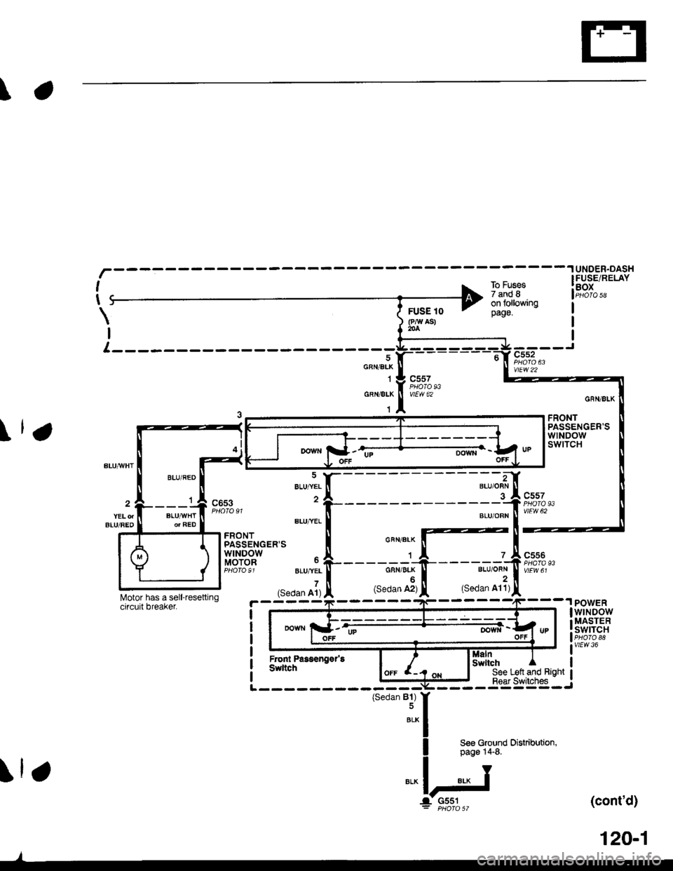
With the ignition switch in ON, voltage is provided to
the coil of the power window relay through fus€ 24.
The contacts of the power window relay close, and
voltage is applied to the driver's switch. When you
push the power window master switch to UP, voltage
is applied to the driver's window motor. (The motor's
ground path is back through the master power
window switch.) The driver's window motor then
drives the window up. When you push the switch to
DOWN, voltage is applied in the opposite direction
and the motor drives the window down.
Automatic Down (Driver's Window)
With the ignition switch in ON or START, voltage is
applied to the coil of the power window relay. The
contacts of the power window relay close and
voltage is applied lo the power window master
switch. When you push the driveas switch to the
AUTO DOWN position, voltage is applied through
the driver's switch to the driver's window motor. The
control unit receives pulses at the pulser input while
the motor is running. When the window is fully
down, the motor stops, and pulses are no longer
generated by the pulser. This is sensed by the
control unit at the pulser input, and voltage is no
longer applied to the driver's window motor.
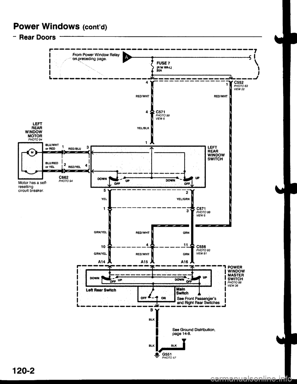
Passenger Windows
With the ignition switch in ON, voltage is applied to
the coil of the power window relay through fuse 24.
The contacts of the power window relay then close,
applying voltage to the individual window switches
and the power window master switch. With the
master panel main switch ON, the passenger
windows can be ooerated from the individual
window switches or from tho master panel switches.
When you push the front passengsr's window
switch to UP, voltage is applied to the f ront
passenger's window motor. (The motor is grounded
through the contacts in the front passenger's
window switch and the oower window master
switch.) The window moves up as long as you hold
the switch in the UP position. lf you push the switch
to DOWN, voltage is applied in th€ opposite
direction to the front passenger's window motor, and
the window movss down as long as you hold the
switch in the DOWN Dosition. The window switches
in the other doors operate similarly.
When you push the front passenger's switch in the
master panel to UP, voltage is applied through the
front passenger's window switch contacts to the
front passengefs window motor. (The motor is
grounded through the contacts in the front
passenger's window switch and the power window
master switch.) The window moves up as long as
you hold the switch in the UP position. lf you push
the switch to DOWN, voltage is applied in the
opposite direction to lhe front passenger's window
motor, and the window moves down as long as you
hold the switch in the DOWN position. The other
passenger window switches in the master panel
operate similarly.
Refer to the Service Manual (Section 23, Electrical)
for specific tests or troubleshooting procedures.
120-4
Page 2021 of 2189
Moonroof (cont'd)
- How the Circuit Works
Moonroof Open
When you push the moonroof switch to the OPEN
position, the moonroof open switch applies ground
to the moonroof "open" relay through the YEL wire.
The moonroof "open" relay applies battery voltage
to the moonroof motor through the GRN/RED wire.
The moonroof "close" relay supplies ground to the
moonroof motor through its normally closed relay
conlacls. When the moonroof moves out of the fully
closed oosition. the tilvclose switch moves to the
OPEN position; the open/close switch moves to the
OPEN oosition.
Moonrool Tilt
When you push the moonroof switch to the TILT
position, the moonroot tilt switch applies ground to
the moonroof "close" relay through the BLU wire,
tilvclose switch and RED wire. The moonroof"close" relay applies battery voltage to the
GRNff EL wire to the moonroof motor. The
moonroof "open" relay supplies ground to the
moonroof motor through its normally closed relay
contacts. When the moonroof is in the tilt oosition,
the trlvclose switch moves to the TILTED position;
the open/close switch moves to the TILTED
Dosition.
Moonroof Close trom the Open Position
When you push the moonroof switch to the CLOSE
position, the moonroof "close" switch applies ground
to the moonroof "close" relay through the YEURED
wire, tilvclose switch and GRN/RED.wire. The
moonroof "close" relay applies battery voltage to the
GRNI/EL wire to the moonroof motor. The
moonroof "open" relay suppfies ground to the
moonroof motor through its normally closed relay
contacts. When the moonroof is fully closed, the
tilvclose switch moves to the closed position; the
open/close switch moves to the CLOSED position.
122-2
Moonroot Close from the Tilt Position
When you push the moonroof switch to the CLOSE
posilion, the moonroof "open" switch applies ground
to the moonroof "close" relay through the YEURED
wire, open/close switch and moonroof "open" relay.
The moonroof "open" relay applies battery voltage to
the moonroof motor through the GRN/RED wire. The
moonroof "close" relay supplies ground to the
moonroof motor through its normally closed relay
contacts. When the moonroof is fully closed, the
tilvclose switch moves to the closed oosition and the
open/close switch moves to the CLOSED position.
Refer to the Service Manual (Section 23, Electrical)
for specific tests or troubleshooting procedures.
Page 2026 of 2189
Power Door Locks (cont'd)
- How the Circuit Works
Keyless Entry System
The keyless door locks combine the power door
locks with a remote keyJob transmitter. The keyless
receiver unit is part of the radio. The keyless
receiver unit receives direct inputs f rom the ignition
key switch, the passenger door switches, and an
indirect input trom the driver's door switch through
the integrated control unit.
Power Door Locks (With or Wlthout Keyless)
The power door lock system is made up of the
oower door lock control unit. driver's door lock
switch, and individual door lock actuators. The
power door locks are controlled by the driver's door
lock switch and the driver's door lock actuator
switch.
Transmitter (With Keyless Entry)
The transmitter sends coded radio wave signals to
the keyless receiver unit when one ot its buttons is
pressed. Each transmitter has a unique code that
must be 'laught" to the keyless receiver unit before
it can operate the door locks or any other lunction.
Up to 4 transmitters can be programmed to operate
the keyless door locks.
Door Locking (With or without Keyless Entry)
When you push the driver's door lock switch to the
lock position, ground is applied to the GBN/IVHT
wire to the oower door lock control unit. The control
unit then applies battery voltage to the WHT/RED
wire and ground to the YEURED wire. The
passenger door lock actuators then activate to lock
the corresponding door locks.
When you lock the driver's door with the key or door
lock knob, it is mechanically locked, and the driver's
door lock actuator switch applies ground to the
oower door lock control unit. The control unit then
applies battery voltage to the WHT/RED wire and
ground to the YEURED wire, activating the
passenger door lock actuators which lock the doors.
Dool Locking with Transmitter
When you press the LOCK button on the remote
transmitter, the power door lock control unit applies
battery voltage to the WHT/RED wire and ground to
the YEURED wire. The passenger door lock
actuators then activate and lock the doors. A ground
slgnal is also applied to the BLU/RED wire to lock
the driver's door. lf any door is open, you cannot lock
it using the remote transmitter.
Door Unlocking (With or Without Keyless Entry)
When you push the driver's power door lock switch
to the unlock position, ground is applied to the
GRN/ORN wire to the power door lock control unit.
The control unit then applies battery voltage to the
YEURED and BLU/RED wires and ground to the
WHT/RED wire. The door lock actuators then
activate to unlock the doors.
When you unlock the driver's door with the key or
the door lock knob, it is mechanically unlocked; the
other doors do not unlock.
Door Unlocking (With Transmltter)
When you press the UNLOCK button on lhe remote
transmitter once. the power door lock control unit
applies battery voltage to the WHT/RED wire and
ground to the BLU/RED wire to unlock the driver's
door. When you press the UNLOCK button twice,
the control unit then applies ground to the YEURED
wires to activate the passenger door locks. lf you do
not open a door within 30 seconds after unlocking
the doors with the transmitter, the doors
automatically relock.
Transmltter Programming
1 . Turn the ignition switch ON (ll).
2. Press and hold the Valet-Disarm button on the
radio (between the AM/FM button and the
CD/TAPE button) to enter the programming
mode. (Continue to hold the button during the
procedure, or programming will be cancelled.)
Check that the power door locks cycle to confirm
that you're in the programming mode.
3. Press the "LOCK' or "UNLOCK' button on the
transmitter. Check that the power door locks
cycle to confirm that the code was accepted.
4. Press the "LOCK" or "UNLOCK" button on each
of the remaining transmitters. (You can program
up to four transmitters per vehicle.)
5. After all the transmitters have been
programmed, release lhe Valet-Disarm button to
exit the programming mode.
Beep On/Oft Feature
'I . Press and hold the LOCK and OPTION buttons
on the transmitter.
2. Watch the transmitter's LED:
One flash: Beeo activated.
Two tlashes: Beeo deactivated.
130-4
Page 2027 of 2189
Keyless Receiver Unit Troubleshooting
lf a faulty keyless receiver unit has one of the symptoms below, turn to the page listed and follow the
appropriate troubleshooting procedure. lf the symptom seems related to an input problem, or is not covered
by the troubleshooting procedures, do the Input Tests on page 130-6. Refer to the circuit schematic on pages
1 30-2 and 130-3 as needed.
Symptom Index
Keyless Entry Does Not Work In Any Mode
Ceiling Light Does Not Come On When The Doors Are Unlocked
WithTheTransmitter ....
Doors Do Not Unlock Or Lock With The Transmitter . . . .
Horn Does Not Sound With The Transmitter "Beeo" Feature On
Horn Does Not Stop Sounding .......
Input Tests
Page 130-8
Page 130-9
Page 130-1 0
Page 130-11
Page 130-11
Page 130-11
Page 130-6
.1,
Page 2031 of 2189
\,113. Recheck with a known good transmitler
reprogrammed to the vehicle. Does the system
work properly in all modes?
Yes - Replace the transmitter and program it by
using the procedure on page 130-4.
No - ReDlace the radio.
\lr
\
Ceiling Light Does Not Come On When
The Doors Are Unlocked With The
Transmitter
NOTE: The vehicle must have a tactory radio installed.
1 . ls the ceiling light switch in the center position?
Yes - Go to the nexl steo.
No - Reposition the ceiling light switch and
retest.
2. Does the ceiling light come on with the ceiling
light switch in the ON position?
Yes - Go to the next step.
No - Repair the ceiling light circuit.
3. Does the transmitter LED come on when anv of
the buttons are oressed?
Yes - Go to the next step.
No - Check the transmitter battery, then retest.
lf the ceiling light still does not work, go to
the next steD.
4. Recheck with a known good transmitter
reprogrammed to the vehicle. Does the system
work properly in all modes?
Yes - Replace the transmitter and program it by
using the procedure on page 130-4.
No - Go to the ne)d steo.
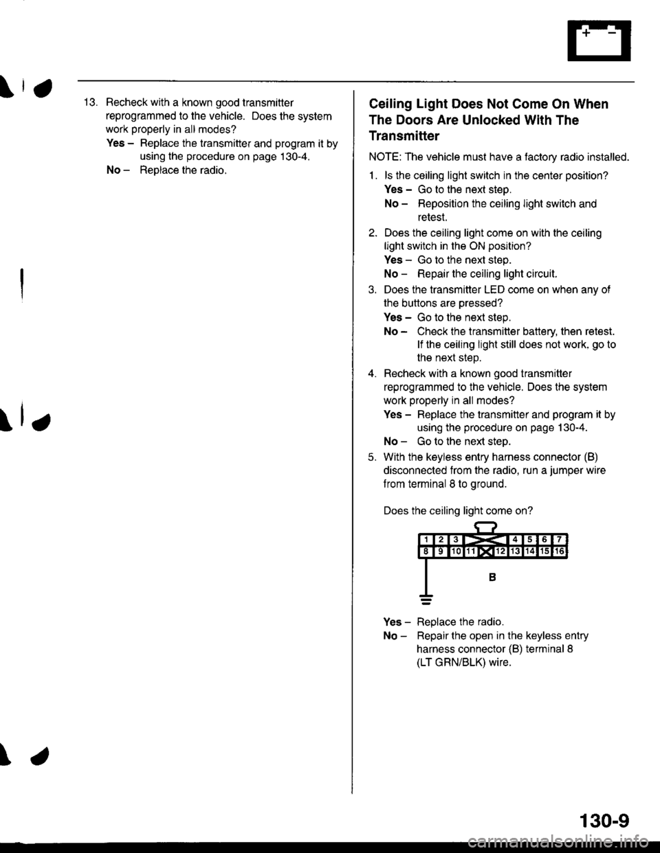
5. With the keyless entry harness connector (B)
disconnected from the radio. run a jumper wire
f rom terminal 8 to ground.
Does the ceiling light come on?
Yes - Replace the radio.
No - Repairthe open in the keyless entry
harness connector {B) terminal 8
(LT GRN/BLK) wire.
130-9
Page 2033 of 2189
a
Horn Does Not Sound In The Panic
Mode Or With The Transmitter "Beep"
Feature On
NOTE: The transmitter has a Beep On/Off feature.
Refer to page 130-4 for how to tum the beep on or
off.
1. Does the horn sound when the HORN button is
oressed?
Yes - Go to the next steD.
No - Repair the horn circuit.
2. Does the transmittor LED come on when any of
the buttons are pressed?
Yes - Go to the next step.
No - Check the transmitter battery then retest.
ll the beep feature still does not work, go
to the next steo.
3. Recheck with a known good transmitter
reprogrammed to the vehicle. Does the system
work properly in all modes?
Yes - Replace and program the transmitter,
then retest. Use the procedure on page
1 30-4 f or transmitter programming.
No - Go to the next step.
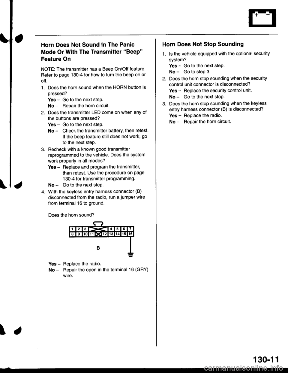
4. With the keyless entry harness connector (B)
disconnected from the radio, run a.iumper wire
f rom terminal 16 to ground.
Does the horn sound?
Yes - Reglace the radio.
No - Repair the open in the terminal 16 (GRY)
wire.
\
Horn Does Not Stop Sounding
1. ls the vehicle equipped with the optional security
system?
Yes - Go to the next step.
No - Go to step 3.
Do€s the horn stop sounding when the security
control unit connector is disconnected?
Yes - Replace the security control unit.
No- Go to the next step.
Does the horn stop sounding when the keyless
entry harness connector (B) is disconnected?
Yes - Reolace the radio.
No - Reoair the hom circuit.
130-11
Page 2036 of 2189
Power Door Locks (conrd)
- How the Circuit Works
Keyless Entry System
The keyless door locks combine the power door
locks with a remote key-fob transmitter. The keyless
door lock control unit receives direct inputs from the
ignition key switch, the passenger door switches,
and an indirect inDut from the driver's door switch
through the integrated control unit.
Power Door Locks
The power door lock system rs made up ot the
keyless door lock control unit, driver's door lock
switch, and individual door lock actuators. The
power door locks are controlled by the driver's door
lock switch and the driver's door lock actuator
switch.
Transmittel
The transmitter sends coded radio wave signals to
the keyless door lock conlrol unit when one of its
buttons is pressed. Each transmitter has a unique
code that must be 'laught" to the conlrol unit before
it can operate the door locks or any other function.
Up to 4 transmitters can be programmed to operate
the keyless door locks.
Door Locking
When you push the driveas door lock switch to the
lock position, ground is applied to the GRNMHT
wire to the keyless door lock control unit. The
control unit then applies battery voltage to the
WHT/RED wire and ground to the YEURED wire.
The passenger door lock actuators then activate to
lock the corresponding door locks.
When you lock the dnver's door with the key or door
lock knob, it is mechanically locked, and the driver's
door lock actuator switch applies ground to the
oower door lock control unit. The control unit then
applies battery voltage to the WHT/RED wire and
ground to the YEURED wire, activating the
passenger door lock actuators which lock the doors.
Door Locking with Transmitter
When you press the LOCK button on the remote
transmitter, the keyless door lock control unil applies
battery voltage to the WHT/RED wire and ground to
the YEURED wire. The passenger door lock
actuators then activate and lock the doors. A ground
signal is also applied to the BLU/RED wire to lock
the driver's door. lf any door is open, you cannot lock
it using the remote transmitter.
Door Unlocking
When you push the driver's power door lock switch
to the unlock position, ground is applied to the
GRN/ORN wire to the keyless door lock control unil.
The control unit then applies battery voltage to the
YEUREO and BLU/RED wires and oround to the
WHT/RED wire. The door lock actuators then
activate to unlock the doors.
When you unlock the driver's door with the key or
the door lock knob, it is mechanically unlocked; the
other doors do not unlock.
Door Unlocking with Transmitter
When you press the UNLOCK button on the remote
transmitter once, the keyless door lock control unit
applies battery voltage to the WHT/RED wire and
ground to the BLU/RED wire to unlock the driver's
door. When you press the UNLOCK button twice,
the control unit then applies ground to the YEURED
wires lo activate the passenger door locks. lf you do
not open a door within 30 seconds after unlocking
the doors with the transmitter, the doors
automatically relock.
Transmitter Programming
. Entering the programming mode cancels all
learned transmitter codes, so none of the
previously programmed transmitters will work.
You must reprogram all the transmitters once
you're in the programming mode.
. To keep the system from exiting the
programming mode, complete each step within 5
seconds of the previous step, and program the
transmitters within 10 seconds of each other.'1 . Turn the ignition switch ON (ll).
2. Press the "LOCK" or "UNLOCK" button on one
of the transmitters. (A non-programmed
transmitter can be used for this step.)
3. Turn the ignition switch OFF (0).
4. Repeat steps 1, 2, and 3 two more times with
the transmitter used in step 2.
5. Turn the ignition switch ON (ll).
6. Press the "LOCK" or "UNLOCK" button on the
same transmitter. Check that the power door
locks cycle to confirm that you're in the
programmrng mooe.
7. Press the "LOCK" or "UNLOCK" button on each
lransmitter. (You can program up to four
lransmitters per vehicle.) Check that the power
door locks cycle after you push each transmitter
button, contirming that the system has accepted
the transmitter's code.
Beep On/Off Feature
1 . Press and hold the LOCK and OPTION buttons
on the transmitter.
2. Watch the transmitter's LED:
One flash: BeeD activated.
Two flashes: Beep deactivated.
130-14