Thrust washer HONDA CIVIC 1998 6.G Owner's Guide
[x] Cancel search | Manufacturer: HONDA, Model Year: 1998, Model line: CIVIC, Model: HONDA CIVIC 1998 6.GPages: 2189, PDF Size: 69.39 MB
Page 1005 of 2189
Secondary Gear Shaft
25 x 35 mm Thrust Shim Selection
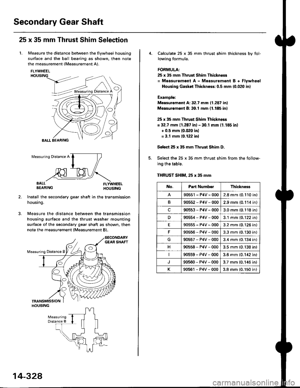
1. Measure the distance between the flywheel housing
surface and the ball bearing as shown, then note
the measurement (Measurement A).
FLYWHEELHOUSING
>dt?'
BALL BEARING
EALL FLYWHEELBEARING HOUSTNG
Install the secondary gear shatt in the transmission
housing.
Measure the distance between the transmission
housing surface and the thrust washer mounting
surface of the secondary gear shaft as shown, then
note the measurement (Measurement B).
O
Measuring Distance A
BALL
14-328
Calculate 25 x 35 mm thrust shim thickness bv fol-
lowing formula.
FORMULA;
25 x 35 mm Thrust Shim Thicknoss
= Measurement A - Measurement B + Flywheel
Housing Gasket Thickness: 0.5 mm {0.020 in}
Example:
Measurement A: 32.7 mm (1.287 in)
Moasurem.nt B: 30.! mm {1.185 in}
25 x 35 mm Thrust Shim Thickness
= 32.7 mm (1.287 in) - 30.1 mm (1.185 in)
+ 0.5 mm {0.020 in)
= 3.1 mm (0.122 inl
Select 25 x 35 mm Thrust Shim D.
Select the 25 x 35 mm thrust shim from the follow-
ing the table.
THRUST SHIM, 25 x 35 mm
No.Part NumberThickne3s
90551 - P4V - 0002.8 mm (0.110 in)
B90552-P4V-0002.9 mm (0.114 in)
c90553-P4V-0003.0 mm (0.118 in)
D90554-P4V-0003.1 mm (0.122 in)
E90555-P4V-0003.2 mm (0.126 in)
90556-P4V-0003.3 mm (0.130 in)
G90557-P4V-0003.4 mm (0.134 in)
H90558-P4V-0003.5 mm (0.138 in)
90559-P4V-0003.6 mm {0.142 in)
90560-P4V-0003.7 mm (0.146 in)
K90561 - P4V - 0003.8 mm (0.'150 in)
Page 1014 of 2189
Transmission
Reassembly
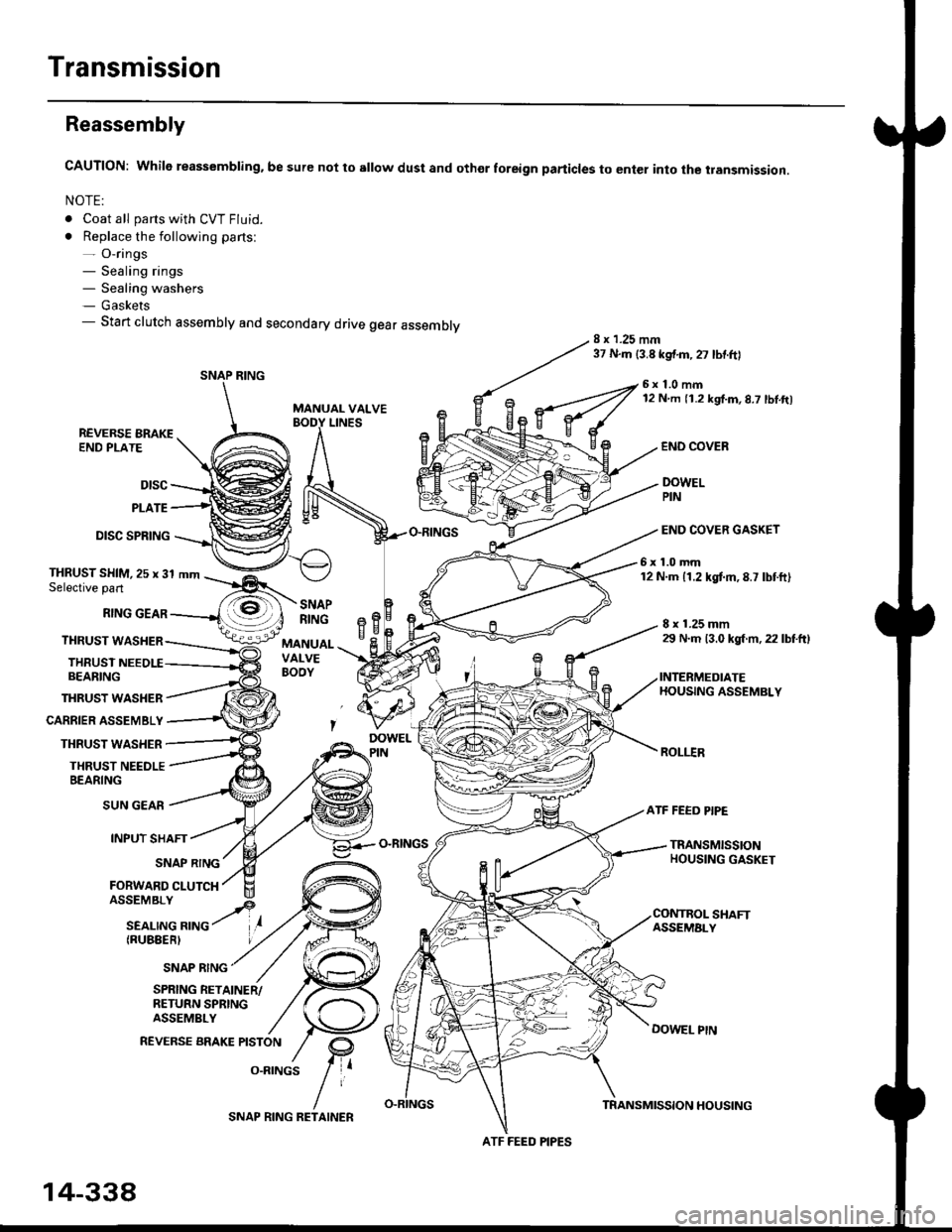
CAUTION: While reassembling. be sure not to sllow dust and othor foreign particles to enter into the transmission.
NOTE:
. Coat all parts with CVT Fluid.
. Replace the following parts:- O-rings- Sealing rings- Sealing washers- Gaskets- Start clutch assembly and secondary drive gear assembly8 x 1.25 mm37 N.m {3.8 kgf.m,27 lbtftl
MANUAL VALVE
6x1.0mm12 N m 11.2 kgf.m,8.7 lbl.ft)
LINESREVERSE BRAKEEND PLATE
Dtsc
PLATE
DISC SPRING
THRUST WASHER
CARRIER ASSEMBLY
THRUST WASHER
THRUST NEEDLEBEARING
END COVEB
DOWELPIN
END COVER GASKET
6x1.0mm12 N.m 11.2 kgtm,8.7 lbtft)THRUST SHIM,25 x 31 mmSelective part
RING GEAR
THRUST WASHER
THRUSTBEARING
8 x 1.25 mm29 N.m 13.0 kgl m, 22 lbtftl
INTERMEDIATEHOUSING ASSEMBLY
ROLI.IR
SNAPRINGeBH^cMANUALVALVEBOOY
SUN GEAR
INPUT SHAFT
(RUBEERI
ATF FEED PIPE
O-RINGSTRANSMISSIONHOUSING GASKETSNAP RING
FORWARD CLUTCH
SNAP RING
SHAFTASSEMALY
DOWEL PtN
SPRING RETAINER/RETURN SPRINGASSEMBLY
REVERSE BRAKE PISTON
O.RINGS
SNAP RING
ATF FEED PIPES
14-338
SNAP RING RETAINERTRANSMISSION HOUSING
Page 1016 of 2189
Transmission
16.
Reassembly (cont'dl
21.
17.
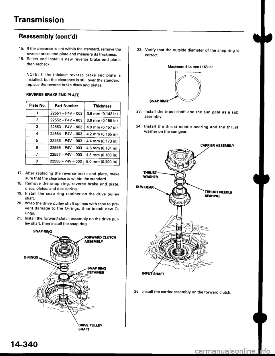
lf the clearance is not within the standard, remove thereverse brake end plate and measure its thickness.Select and install a new reverse brake end Dlate.then recheck.
NOTE: lf the thickest reverse brake end olate isinstalled, but the clearance is still over the standard,replace the reverse brake discs and plates.
REVERSE BRAKE END PLATE
After replacing the reverse brake end plate, makesure that the clearance is within the standard.Remove the snap ring, reverse brake end plate,
discs, plates. and disc spring.
Install the snap ring retainer on the drive pulley
shaft.
Wrap the drive pulley shaft splines with tape to pre-
vent damage to the O-rings, then install new O-n ngs.
Install the forward clutch assembly on the drive pul-
ley shaft, then installthe snap ring.
SITAP
O-RINGS
18.
19.
20.
SI{AP RIM;BETA EB
DRIVE PUI.IEYSHAFT
Plat6 No.Part NumberThickness
122551 - P4V - 0033.6 mm (0.142 in)
22552-P4V-0033.8 mm (0.150 in)
22553-P4V-0034.0 mm (0.157 in)
422554-P4V-0034.2 mm (0.165 in)
522555-P4V-0034.4 mm (0.173 in)
622556-P4V-0034.6 mm (0.181 in)
722557 -P4V -OO34.8 mm (0.189 in)
822558-P4V-0035.0 mm (0.200 in)
14-340
25. Installthe carrier assembly on the forward clutch.
22. Verity that the outside diameter ol the snap ring iscorrect.
SI{AP RIiIG
Install the input shaft and the sun gear as a subassemDry.
Install the th.ust needle bearing and the thrustwasher on the sun gear.
CARRIER ASSEMBLY
THFUST I'IEEDI!EEARIT{G
Msximum 41.4 mm 11.63 in)
IHruST
Page 1017 of 2189
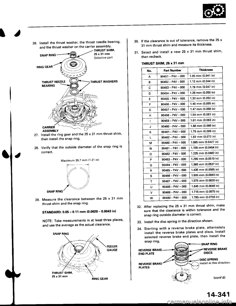
26. Install the thrust washer, the thrust needle bearing'
and the thrust washer on the carrier assembly'
SNAP RING
THRUST SHIM,
25x31 mm
Selective Pan
21.
24.
RING GEAR
THRUST NEEDLETHRUST WASHERS
EEARING
CARRIERASSEMBLY
lnstallthe ring gear and the 25 x 31 mm thrust shim,
then installthe snaP rrng.
Verify that the outside diameter of the snap ring is
correct,
Maximum 30.7 mm (1.21 in)
SNAP RING
Measure the clearance between the 25 x 31 mm
thrust shim and the snaP rlng.
STANDARD: O.O5 - 0.11 mm (0.0020 - 0.00'8 in)
NOTE: Take measurements in at least three places'
and use the average as the actual clearance
29.
,**r#*,".
'- t )
RING GEAR
14-341
30.
31.
lf the clearance is out of tolerance, remove the 25 x
31 mm thrust shim and measure its thickness'
Select and install a new 25 x 31 mm thrust shim.
then recheck.
THRUST SHIM, 25 x 31 mm
snap nng.RING
After replacing the 25 x 31 mm thrust shim, make
sure that the clearance is within tolerance and the
snap ring outside diameter is correct'
Install the disc spring in the direction shown'
Starting with a reverse brake plate, alternately
install the reverse brake plates and discs lnstall
selected reverse brake end plate, then install the
32.
33.
34.
REVERSEEND PLATE
BRAKE
Dtscs
SPRINGlnstall in this direction.
(cont'd)
REVERSEPI-ATES
No.Part Numb.lThickne*3
90451 - P4V - 0001.05 mm (0.041 in)
B90452-P4V-0001.12 mm (0.044 in)
c90453-P4V-000'1.19 mm (0.047 in)
D90454 - P4V - 000'l.26 mm (0.050 in)
90455-P4V-0001.33 mm (0.052 in)
F90456-P4V-0001.40 mm (0.055 in)
904s7-P4V-0001.47 mm (0.058 in)
90458-P4V-0001.54 mm (0.06'l in)
90459-P4V-000'1.61 mm (0.063 in)
J90460-P4V-0001.68 mm (0.066 inl
K90461-P4V-0001.75 mm (0.069 in)
90462-P4V-0001.82 mm (0.072 in)
M904a0-P4V-0001.085 mm (0.0427 in)
N90481-P4V-0001.155 mm (0.0454 in)
o901a2-P4V-0001.225 mm (0.0482 in)
90483-P4V-0001.295 mm (0.0510 in)
o90484-P4V-0001.365 mm (0.0537 in)
R904a5-P4V-0001.435 mm (0.0565 in)
90486-P4V-0001.5O5 mm (0,0593 in)
T90487-P4V-0001.575 mm (0.0620 in)
90488-P4V-00{)1.645 mm {0.0648 in)
90489-P4V-0001.715 mm (0.0675 in)
90490-P4V-0001.785 mm (0.0703 in)
Page 1019 of 2189
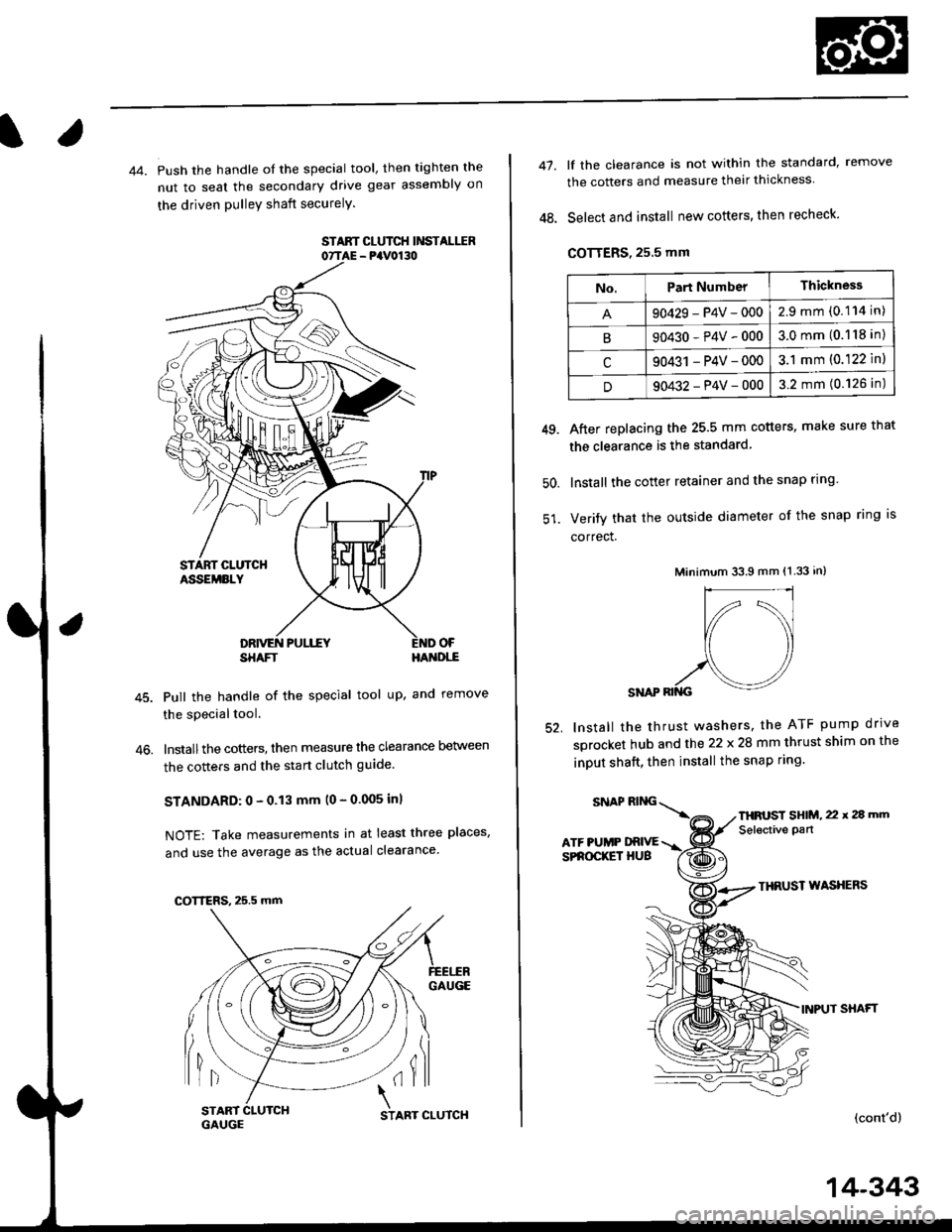
44. Push the handle of the special tool, then tighten the
nut to seal the secondary drive gear assembly on
the driven pulleY shaft securelY.
STAAT CLUTCH Ii'ISTALIIR07TAE - PaV0130
OF
46.
SHAFTHA'{DI,-E
Pull the handle of the special tool up, and remove
the special tool.
lnstallthe cotters, then measure the clearance Delween
the cotters and the start clutch guide
STANDARD: 0 - 0.13 mm (0 - 0.005 inl
NOTE: Take measurements in at least three places,
and use the average as the actual clearance
GAUGE
lil(il
COTTERS, 25.5 mm
START 1
GAUGCSTART CLUTCH
14-343
47.
48.
lf the clearance is not within the standard, remove
the cotters and measure their thickness
Select and install new cotters, then recheck.
COTTERS, 25.5 mm
After replacing the 25.5 mm cotters, make sure that
the clearance is the standard
lnstall the cotter retainer and the snap rlng
Verify that the outside diameter of the snap ring is
correct.
Minimum 33.9 mm (1.33 in)
SNAP RII{G
lnstall the thrust washers. the ATF pump drrve
sprocket hub and the 22 x 28 mm thrust shim on the
inDUt shaft, then install the snap ring.
49.
50.
52.
THRUST WASXERS
INPUT SHAFT
(cont'd)
No.Part NumberThickness
90429-P4V-0002.9mm(0.114 in)
B90430-P4V-0003.0mm(0.118 in)
c90431 -P4V-0003.1 mm (0.122 ln)
D90432-P4V-0003.2 mm (0.126 in)
SNAPRING\
ATF PUMP DRIVESPROCKET HUB
THFUST SHIM, 22 x 2a mm
Selective pan